Article

Experimental Validation of Exact Burst Pressure Solutions for Thick-Walled Cylindrical Pressure Vessels

Materials Technology and Energy Science, Savannah River National Laboratory, Aiken, SC 29808, USA
Appl. Mech. 2025, 6(1), 20; https://doi.org/10.3390/applmech6010020
Submission received: 22 November 2024 / Revised: 29 January 2025 / Accepted: 3 March 2025 / Published: 5 March 2025
(This article belongs to the Collection Fracture, Fatigue, and Wear)

Abstract

:
Burst pressure is one of the critical strength parameters used in the design and operation of pressure vessels because it represents the maximum pressure that a vessel can withstand before failing. Historically, the Barlow formula was used as a design base for estimating burst pressure. However, it does not consider the plastic flow response for ductile steels and is applicable only to thin-walled cylinders (i.e., the diameter to thickness ratio D/t ≥ 20). A new multiaxial plastic yield theory was developed to consider the plastic flow response, and the associated theoretical (i.e., Zhu–Leis) solution of burst pressure was obtained and has gained extensive applications in the pipeline industry because it was validated by different full-scale burst test datasets for large-diameter, thin-walled pipelines in a variety of steel grades from Grade B to X120. The Zhu–Leis flow theory of plasticity was recently extended to thick-walled pressure vessels, and the associated exact flow solution of burst pressure was obtained and is applicable to both thin and thick-walled cylindrical shells. Many full-scale burst tests are available for thin-walled line pipes in the pipeline industry, but limited pressure burst tests exist for thick-walled vessels. To validate the newly developed exact solutions of burst pressure for thick-walled cylinders, this paper conducts a series of burst pressure tests on small-diameter, thick-walled pipes. In particular, six burst tests are carried out for three thick-walled pipes in Grade B carbon steel. These pipes have a nominal diameter of 2.375 inches (60.33 mm) and three nominal wall thicknesses of 0.154, 0.218, and 0.344 inches (3.91, 5.54, and 8.74 mm), leading to D/t = 15.4, 10.9, and 6.9, respectively. With the burst test data, comparisons show that the Zhu–Leis flow solution of burst pressure matches well the burst test data for thick-walled pipes. Thus, these burst tests validate the accuracy of the Zhu–Leis flow solution of burst pressure for thick-walled cylindrical vessels.

1. Introduction

Pressure vessels and pipelines are important national infrastructures that are broadly utilized in the storage or transport of natural gas, gasoline, oil, or other hazardous liquids in the energy industry. Thus, the structural design, manufacture, construction, and integrity management of pressure components are critical to ensure the safe operation of these infrastructures. Among different design parameters, burst pressure is an important strength parameter used in the design and operation of pressure components because it represents the maximum pressure that a pressure vessel can withstand before rupturing or failing. The burst pressure is usually determined based on the material tensile strength and pressure vessel geometry and is often used for design validation and safety assessment to ensure the pressure vessel is sufficiently strong and stable.
Traditionally, burst pressure was estimated from a simple design model that was developed based on one of the classic strength theories, experimental test data, numerical simulation results, empirical formulae, or industrial design codes [1]. Many pressure vessels and pipelines are large-diameter, thin-walled cylindrical shells, leading to a large diameter-to-thickness ratio D/t ≥ 20 [2,3]. In contrast, many other pressure components involve small-diameter, thick-walled pipes with a small diameter-to-thickness ratio D/t < 20 [3,4]. Over the past decades, numerous simple burst models have been developed for cylindrical pressure vessels. Hamada et al. [5] and Christopher et al. [6,7] summarized the available burst pressure models for thick-walled pressure vessels, whereas Law and Bowie [8] and Zhu and Leis [9] assessed the existing burst pressure models for thin-walled line pipes. Many industry designs or assessment codes were developed based on the Barlow formula using the yield stress (YS) of the material for estimating limit pressure or using the ultimate tensile stress (UTS) of the material for estimating burst pressure. Recently, Zhu [1] compared the traditional strength criteria versus the modern plastic flow criteria used in the design and analysis of pressure vessels, Wang et al. [10] analyzed a set of burst prediction models for structural steels exhibiting a yield plateau, and Sun et al. [11] reevaluated the burst prediction models for various pipeline steels.
Literature reviews have determined that no single burst pressure model can predict an accurate result of burst pressure for all ductile steels. Some models predict a conservative lower bound, but other models may predict an upper bound. Many early design models were developed using the hoop stress and one material strength property (i.e., YS or UTS), such as the Barlow formula, but the effect of strain hardening was not considered in these early design models. In the mid-1990s, Steward and Klever [12] first found that the strain hardening of the material had a strong effect on the burst pressure test data for thin-walled pressure vessels in ductile steels, leading to a large scatter within two limit bounds. The upper limit of the burst test data is bounded by the von Mises solution of burst pressure [13,14], while the lower limit of the burst test data is bounded by the Tresca solution of burst pressure [12]. Their averaged result provides a good fit to the burst test data, on average.
To determine more accurate burst pressure for ductile pipeline steels, Zhu and Leis [15] proposed a new multiaxial plastic yield theory that was named the average shear stress yield criterion, or simply the Zhu–Leis criterion in the literature. From this new yield criterion, the associated Zhu–Leis flow solution of burst pressure was obtained for pipeline carbon steels and demonstrated the great agreement between the Zhu–Leis flow solution and the burst test data for a variety of thin-walled line pipes [9,15]. Many other researchers [16,17,18,19,20] also validated the Zhu–Leis flow solution using other burst test datasets for various pipeline steels, including steel grades from Grade B to X120. Typically, Grade B, X42, and X52 are the low-strength steels and were commonly used for vintage transmission pipelines before the 1970s, whereas X60, X65, and X70 are the middle to high-strength steels and have been frequently used for transmission pipelines since the 1980s. Morden X70 and X80 are high-strength steels and are often used for modern gas transmission pipelines. X100 and X120 are ultra-high-strength steels and remain in the trial and experimental study stage. All the experimental validations show that the Zhu–Leis flow solution is the best burst prediction model for thin-walled pipes. However, this validated burst model is not applicable to thick-walled pipes or cylinders.
For a thick-walled cylindrical shell subject to internal pressure, in the late 1950s, Svensson [14] applied the von Mises flow theory to the theoretical analysis of burst pressure for thick-walled cylinders. Unfortunately, this author did not obtain an exact burst pressure solution for the thick-walled cylinders. Instead, a tabular data solution and an approximate closed-form equation of burst pressure were given. Since then, no further theoretical study on this topic has been reported in the literature. Until recently, Zhu et al. [21] proposed a modified strength theory and obtained an associated burst pressure solution for thick-walled line pipes as a function of Do/Di, UTS, and n, where Do is the outside diameter, Di is the inside diameter of the cylinder, and n is the strain hardening exponent of the material. Moreover, Zhu et al. [22,23] obtained an exact theoretical solution of burst pressure for thick-walled pressure vessels using three flow theories of plasticity. Comparisons showed that the exact theoretical solutions obtained in Ref [22,23] are identical to the burst pressure solutions obtained in Ref [21] from the modified strength theory. The exact Zhu–Leis flow solution of burst pressure for thick-walled pipes has been applied to develop corrosion assessment models for oil and gas transmission pipelines containing corrosion blunt defects [24].
In order to further validate the newly proposed exact theoretical solution of burst pressure for thick-walled cylindrical shells, this paper reports a set of experimental results on the burst pressure tests that were recently conducted at the Savannah River National Laboratory (SRNL) for three thick-walled pipes in Grade B carbon steel. These carbon steel pipes have a nominal diameter of 2.375 inches (60.33 mm) and three nominal wall thicknesses of 0.154, 0.218, and 0.344 inches (3.91, 5.54, and 8.74 mm), leading to D/t = 15.4, 10.9, 6.9, respectively. The burst test data are compared with the proposed exact burst pressure solution. The good agreement with the burst test data validates the accuracy of the Zhu–Leis flow solution of burst pressure for thick-walled pipes. Furthermore, additional existing datasets of burst tests for thin and thick-walled pipes further validate the proposed exact solution of burst pressure developed for thick-walled pipes or cylindrical vessels.

2. Burst Prediction Models for Cylindrical Pressure Vessels

This section briefly discusses the representative burst pressure prediction models for both thin and thick-walled cylindrical vessels under the end-capped conditions and then compares these models to show the differences.

2.1. Burst Pressure Models for Thin-Walled Cylinders

2.1.1. Strength Models for Thin-Walled Cylinders

For a large-diameter, thin-walled cylinder subject to internal pressure, four strength models of burst pressure were obtained using the UTS or the empirical flow stress, in reference to the Tresca, von Mises, and Zhu–Leis strength theories as follows [1]:
  • Tresca strength solution:
P 0 = 2 t D σ u t s
  • von Mises strength solution:
P M 0 = 4 t 3 D σ u t s
  • Zhu–Leis strength solution:
P A 0 = 1 2 1 + 2 3 2 t D m σ u t s
  • Flow stress-based failure solution:
P f l o w = 2 t D σ f l o w
where D is the outside diameter (OD), D m = D t is the mean diameter (MD), and t is the wall thickness. The flow stress is defined as σflow = (σys + σuts)/2, with σys the YS and σuts the UTS. The Zhu–Leis strength solution in Equation (3) was determined using the average shear stress strength theory proposed by Zhu and Leis [15]. Equations (1)–(3) show that the Zhu–Leis strength solution of burst pressure is equivalent to the averaged result of the Tresca and von Mises strength solutions. The Tresca strength solution in Equation (1) is often known as the Barlow formula in the pipeline industry.
The strength models of burst pressure in Equations (1)–(3) were obtained from traditional strength theory using the UTS and thus are independent of the strain hardening rate. Among the four strength models, only the empirical flow stress model considers the strain hardening rate effect on burst pressure. Accordingly, the flow theory of plasticity was recommended [1] for use to develop more accurate burst pressure models based on the two material property parameters of UTS and YS (or n).

2.1.2. Flow Models for Thin-Walled Cylinders

To improve the accuracy of the above-discussed strength models for predicting the burst pressure of thin-walled cylinders, Zhu and Leis [15] considered the effect of the strain hardening rate of the material on burst pressure based on the flow theory of plasticity and the large deformation formulation. In thin-walled shell theory, stresses and strains are assumed constant through the wall thickness of the shell, and thus, the mean diameter is more adequate to use. For a power-law strain hardening steel, the following flow solutions of burst pressure were obtained for thin-walled pipes based on the three yield criteria outlined as follows:
P b = C 2 n + 1 4 t D m σ u t s
where C is a yield criterion-dependent constant:
C = 1 , f o r   T r e s c a   y i e l d   c r i t e r i o n 2 3 , f o r   v o n   M i s e s   y i e l d   c r i t e r i o n 1 2 + 1 3 , f o r   Z h u L e i s   y i e l d   c r i t e r i o n
In Equation (5), the strain hardening exponent n is usually measured from a simple tensile test or estimated from the YS to UTS ratio [15]. For pipeline carbon steels, n typically ranges from 0.02 to 0.25. For an elastic–perfectly plastic material, n = 0, the flow solutions of burst pressure in Equation (5) reduce to the traditional strength models in Equations (1)–(3). Extensive full-scale burst test data [9,15,16,17,18,19,20,25,26,27] have validated the proposed flow burst pressure solutions in Equation (5) for thin-walled pipes in a variety of pipeline steels from Grade B to X100 and demonstrated that the Zhu–Leis flow solution of burst pressure is the most accurate burst prediction model.

2.2. Burst Pressure Models for Thick-Walled Cylinders

2.2.1. Strength Models for Thick-Walled Cylinders

For thick-walled pressure vessels, the thin shell theory becomes invalid, and the thick shell theory must be adopted. In the 1950s to 1970s, many investigators (e.g., Faupel [28,29]) conducted valuable burst pressure tests on small-diameter, thick-walled pressure tubes (i.e., D/t < 10) with end-closed caps for various structural steels. Based on the burst test data, analytical and empirical burst pressure models were proposed for thick-walled tubes. The following three representatives of the strength models of burst pressure are often used for thick-walled pressure vessels [21,22] as follows:
  • Tresca strength solution:
P b = σ u t s ln D o D i
  • von Mises strength solution:
P b = 2 3 σ u t s ln D o D i
  • Svensson approximate solution:
P b = 0.25 n + 0.227 e n n σ u t s ln D o D i
The approximate solution in Equation (9) was obtained by Svensson [14] based on the von Mises flow theory of plasticity. In the above equations, Di is the inside diameter of the cylinder, and Do is the outside diameter of the cylinder.

2.2.2. Flow Models for Thick-Walled Cylinders

A modified strength theory solution. To obtain a more accurate burst pressure solution for thick-walled cylindrical vessels, Zhu et al. [21] proposed a modified strength theory and then obtained the associated burst pressure solution for thick-walled cylindrical shells in terms of the Tresca, von Mises, and Zhu–Leis yield criteria as follows:
P b = 2 C 2 n + 1 σ u t s   l n D o D i
where C is a yield criterion-dependent constant; see the definition in Equation (6).
An exact burst pressure solution. Recently, Zhu et al. [22,23] obtained the exact solutions of burst pressure for thick-walled cylinders in a function of power series using the flow theory of plasticity based on the Tresca, von Mises, and Zhu–Leis criteria, respectively. Appendix A presents these exact solutions of burst pressure for thick-walled cylinders. As shown in Figure A1, these power series solutions of burst pressure are equivalent to the simple logarithmic burst pressure solution in Equation (10).

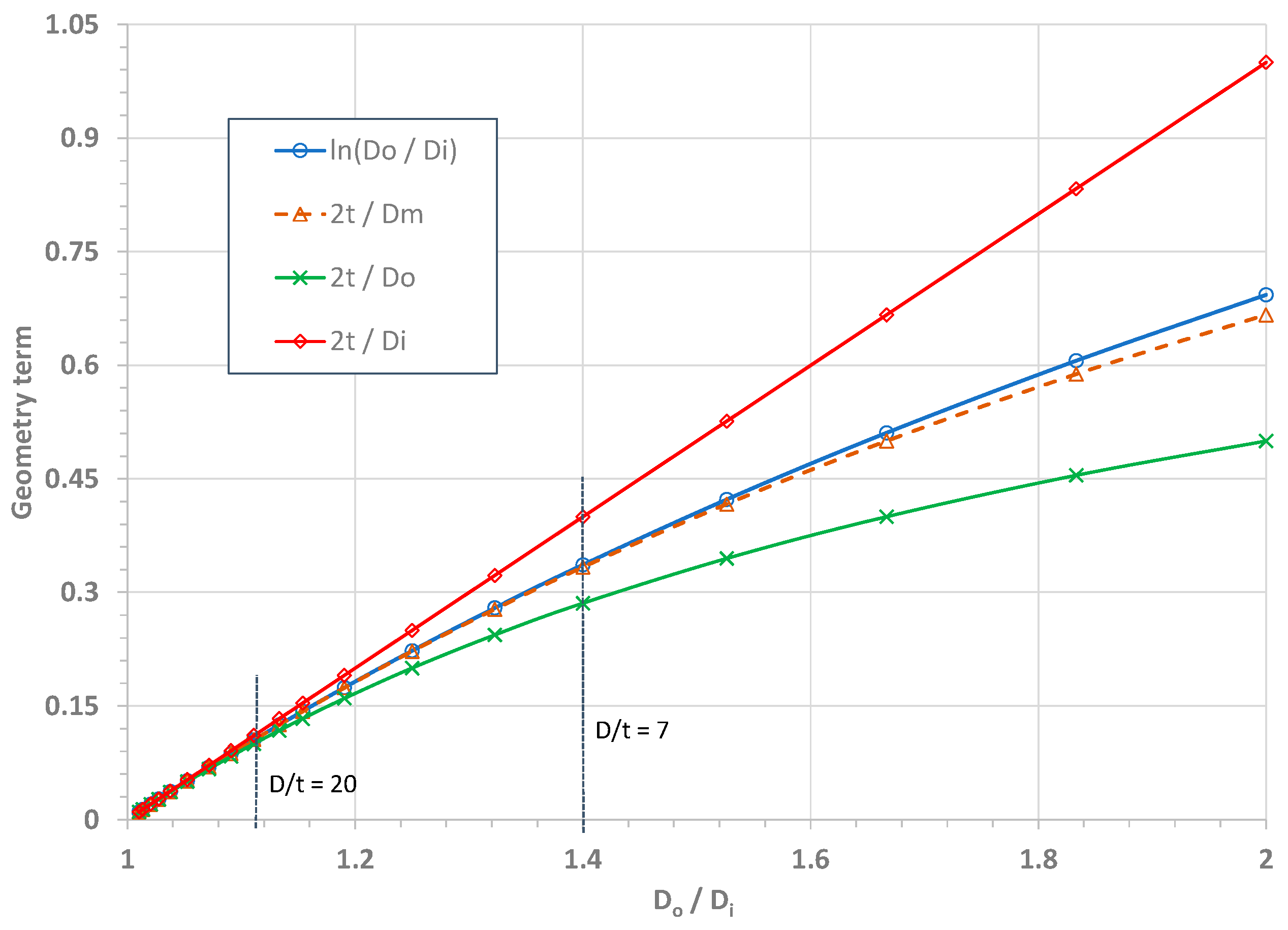
2.3. Comparison of Thin and Thick-Wall Burst Pressure Models

Comparison of Equations (5) and (10) shows that the material terms in the two types of burst pressure solutions are the same for thin and thick-walled cylindrical shells, but their geometry terms are different. For thin-walled cylinders, the geometry term is 2t/Dm, but for thick-walled cylinders, the geometry term is ln(Do/Di). Using the Taylor series, the logarithmic function, ln(Do/Di), can be approximated as a simple function as follows:
ln D o / D i = 2 t / D m + O ( t / D m ) 3
where Dm is the mean diameter of the cylinder, and the term O ( t / D m ) 3 denotes the higher-order terms of the Taylor series. As evident in Equation (11), the exact burst pressure solutions in Equation (10) reduce to the approximate burst solution in Equation (5) when the wall thickness t ≤ D/20, and their difference becomes negligibly small. As a result, the exact solutions of burst pressure in Equation (10) are applicable to both thick and thin-walled cylindrical shells for strain-hardening materials and for elastic–perfectly plastic materials when n = 0.
Figure 1 compares the four geometry terms of l n ( D o / D i ) , 2 t / D m , 2 t / D o , and 2 t / D i for a large range of the diameter ratios (Do/Di).
In general, thin-walled pipes are defined as Do/t ≥ 20. At D/t = 20, the geometry terms 2 t / D m , 2 t / D o , and 2 t / D i have an error of −0.1%, −5.1%, and +5.5%, respectively, compared to the logarithmic term. For a large-diameter ratio (i.e., Do/Di > 1.25), the term 2t/Di significantly overestimates the logarithmic function, the term 2t/Do considerably underestimates the logarithmic function, and the term 2t/Dm is the best one close to the logarithmic function over the wide range of Do/Di ratios. At D/t = 7 for a thick-walled pipe, 2t/Dm has an error of less than −1% compared to the logarithmic function. As a result, 2t/Dm is more accurate to use for thin and intermediate-walled pipes.

3. Experimental Validation

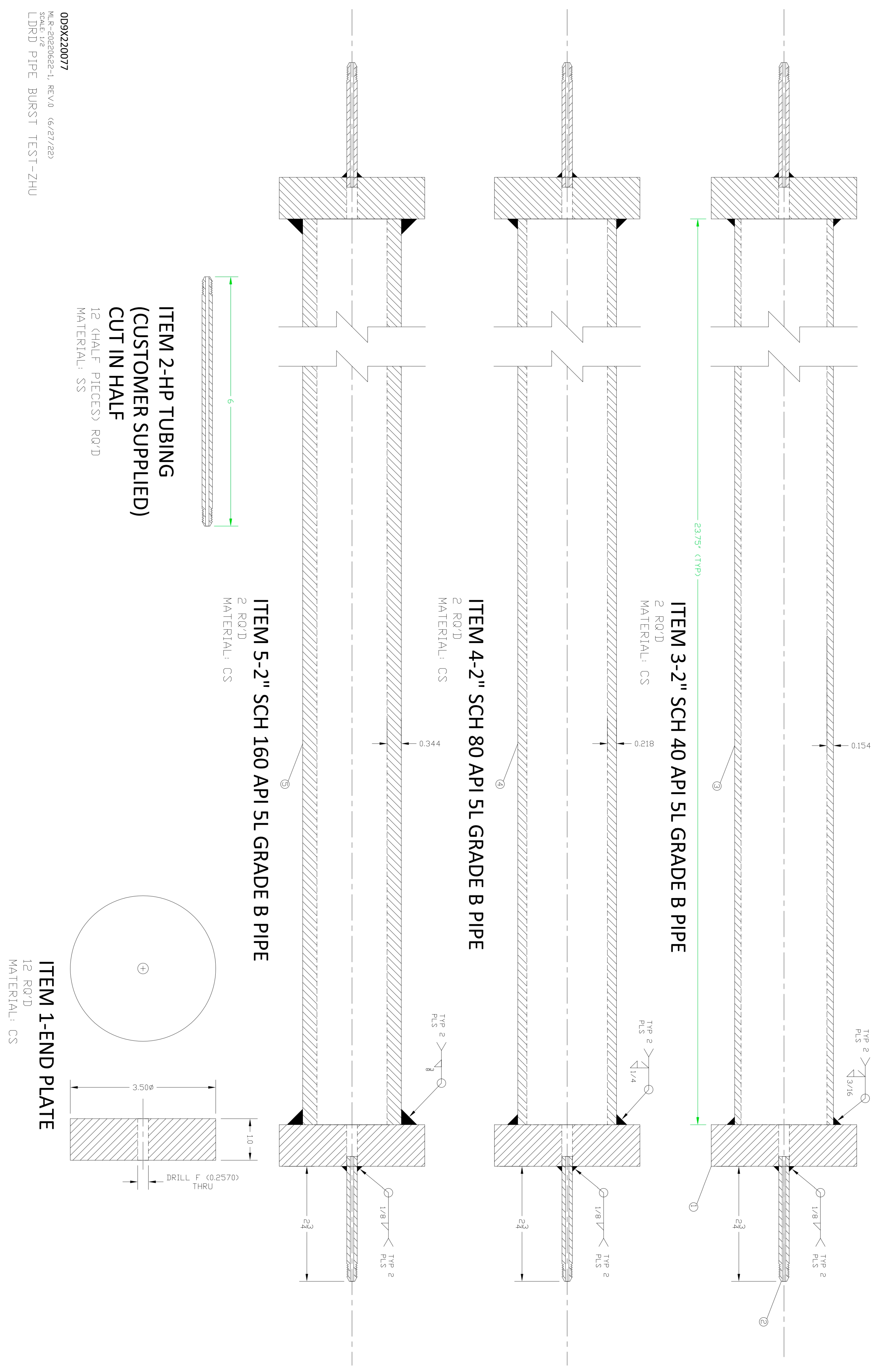
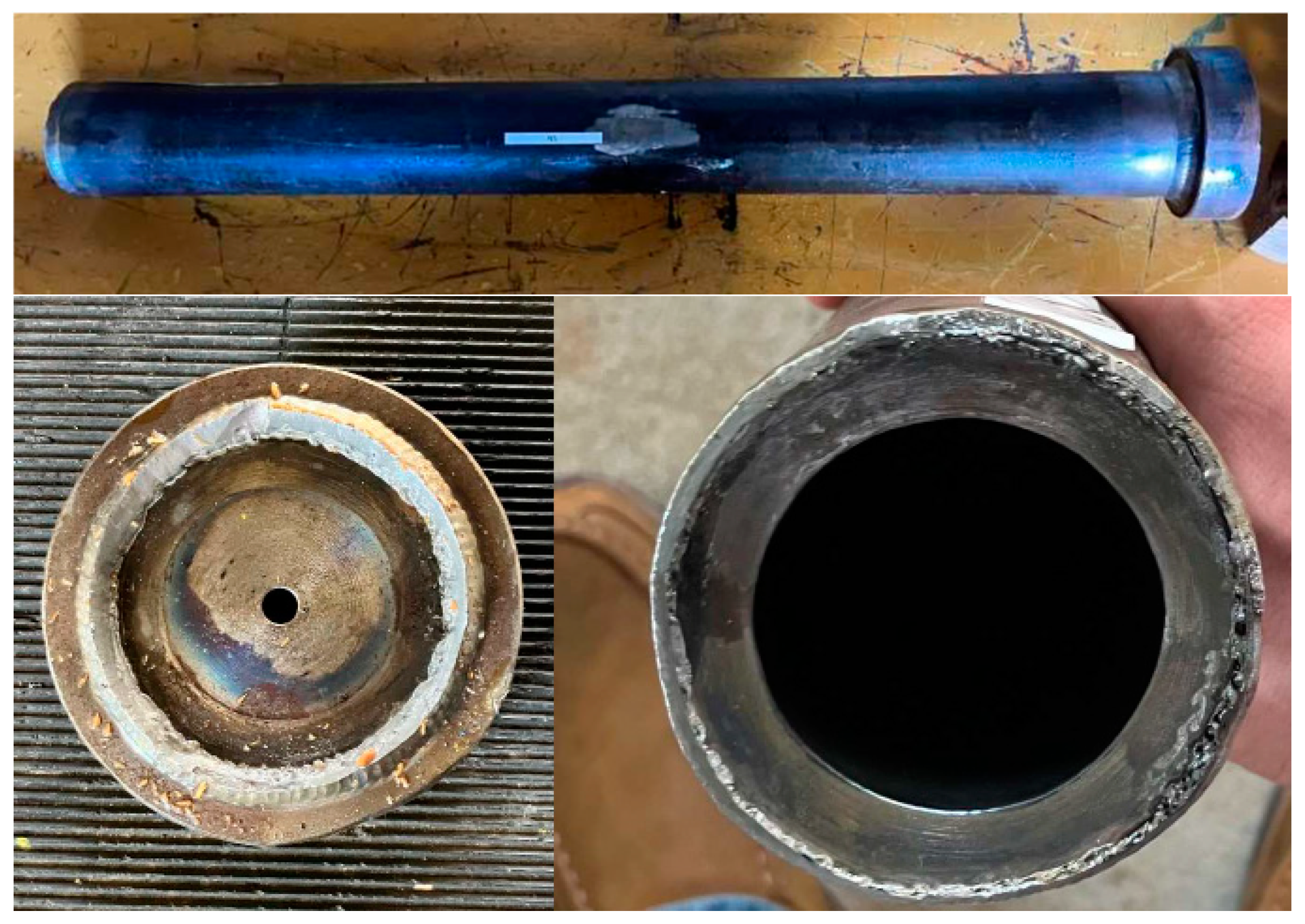
3.1. Grade B Carbon Steel Pipes
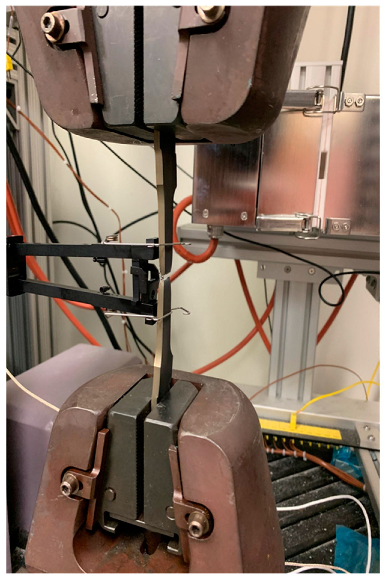
In 2022, the U.S. Department of Energy (DOE) sponsored an R&D program at SRNL to develop an advanced plasticity theory and its experimental validation. After the theoretical solutions of burst pressure were developed for thick-walled pipes [21,22,23], a series of validation burst pressure tests were carried out at SRNL. Three 2-inch black seamless carbon steel pipes specified as ASTM 106B or API 5L Grade B [30] were purchased from Eastern Industrial Supplies, Inc. in Augusta, Georgia [31]. Each carbon steel pipe, as shown in Figure 2, has the same nominal diameter (OD) of 2.375 inches (60.33 mm) and a length of 21 feet (6.4 m). These small-diameter steel pipes have three nominal wall thicknesses of 0.154 inches (3.91 mm), 0.218 inches (5.54 mm), and 0.344 inches (8.74 mm). These wall thicknesses of the pipes correspond to SCH-40, SCH-80, and SCH-160 Grade B carbon steels, respectively [31]. This leads to three nominal diameter-to-thickness ratios of D/t = 15.4, 10.9, and 6.9, respectively. Note that pipe schedule (SCH) is a standard measure of the nominal wall thickness of a line pipe in the pipeline industry. Tensile test small-scale specimens and burst test full-scale pipe specimens were cut and machined from these three Grade B carbon steel pipes.

3.2. Tensile Tests

Six tensile specimens were cut from the Grade B carbon steel pipes in the axial direction. Two specimens were machined for each schedule of the three pipes. Figure 3 shows the six tensile sheet specimens with full thicknesses of the steel pipes.
All sheet specimen dimensions met the tensile test requirements described in ASTM E8-21 [32]. The gauge length of an extensometer is 2 inches (50.8 mm), and the specimen width in the gauge area ranges from 7.5 mm to 8.8 mm.
With the guideline of the tensile test standard methods recommended in ASTM E8-21 [32], all six uniaxial tensile specimens were tested at room temperature in the quasi-static loading conditions at the strain rate of about 0.015 mm/mm/min, and six stress–strain curves were measured. Figure 4 shows the tensile specimen fixture, extensometer, and broken specimen after the tensile test. For each thickness, two specimens were tested, and the two corresponding stress–strain curves were comparable. The yield strength and the ultimate tensile strength were obtained as the averaged values of the two repeated tests.
Figure 5 shows three representative engineering stress–strain curves measured for the three Grade B carbon steel pipes with nominal wall thicknesses of 0.154, 0.218, and 0.344 inches. Note that the specimen sizes used for the stress calculations were measured accurately with a digital micrometer.
As shown in Figure 5, the thinner-walled (0.154 inch) steel pipe has a significantly different stress–strain curve from those of the two thick-walled (0.218 and 0.344 inch) steel pipes. The two thicker-walled steel pipes have comparable stress–strain curves. The reason for the difference is yet unknown. The possible factors may include (1) different manufacturing processing, and (2) small variation of the material composition from different manufacturers, even for the same steel grade. For example, the manufacture of the thin-walled pipe may be different from the manufacture of the other thick-walled pipes. If this is the case, the tensile properties, including the YS, UTS, and stress–strain curves, can be different for the same labeled Grade B steel.
From Figure 5, the yield stress defined at 0.5% total strain is determined as 450, 342, and 356 MPa (65.3, 49.6, and 51.6 ksi), respectively, for the SCH-40, SCH-80, and SCH-160 steel pipes. The UTS is determined as 470, 515, and 531 MPa (68.2, 74.7, and 77.0 ksi), respectively, for the three steel pipes. The strain hardening exponent n is estimated as 0.062, 0.161, and 0.156, respectively, for the three steel pipes. The elongation was measured as 37%, 43%, and 46%, respectively, for the three steel pipes. These material properties are summarized in Table 1.
Note that the material properties reported in Table 1 were measured in the axial direction of the steel pipes. The material properties may be different somehow in the circumferential direction of these steel pipes. Because of the small diameters of the pipes, the standard tensile specimens are impractical to machine in the circumferential direction, and thus, the mechanical properties in the circumferential direction were not measured in the tensile tests.

3.3. Pressure Burst Tests and Results

A series of pressure burst tests were then completed at SRNL to determine the maximum pressure carry capacity of API 5L Grade B black seamless carbon steel pipes [31]. Six pipe specimens, two specimens for each pipe schedule, were instrumented and tested. The actual diameter was 2.375 inches (60.33 mm) for all the pipe specimens, and the actual wall thicknesses were 0.147 inches (3.73 mm), 0.214 inches (5.44 mm), and 0.347 inches (8.81 mm). Note that these actual measured wall thickness values are slightly different from the nominal thickness values introduced previously. Preparations of the pipe specimens, instrumentation, test results, and discussions are summarized in Report [31]. Machinists in the SRNL machine shop manufacture each pipe specimen. Appendix B details the burst test pipe specimen design drawing. High-strength circular steel plates with a diameter of 3.5 inches (88.9 mm) and a thickness of 1.0 inches (25.4 mm) were cut and welded to the end of each pipe to ensure the pipe bursting was preferential to the end fitting. The high-pressure pipe fittings were also fitted to the middle of each plate at the ends of each pipe specimen. After the machine shop completed manufacturing the specimens, the strain gauge installation process was started. A full Wheatstone bridge was desired in the middle of each pipe. Apart from SCH-80 Pipe 2 and SCH-160 Pipe 2, six Omega SGT-3N/350-TY43 strain gauge transducers (manufactured by Omega USA, Michigan City, IN, USA) were installed on each pipe. A pair of strain gauges were installed at an established point in the center of the pipe length.
Surface preparation was a lengthy process for the API 5L Grade B carbon steel pipe. The pipe has a thick oxidation layer that must be removed to present the clean homogenous pipe material. Good adhesion is necessary for the strain gauges to be successful in data collection. Micro-Measurements, a VPG company, provided the instruction and surface prep materials used in this strain gauge installation process. This involved degreasing the surface, mildly abrading with sandpaper, conditioning the surface, and neutralizing the surface. The strain gauge was then adhered with a special adhesive.
Figure 6 shows an example of the pressure burst test setup for SCH-40 Pipe 1. The other burst test pipes have a similar experimental setup. All the pipe specimens have a length of 10OD = 23.75 inches (603.3 mm) at least. Two 1-inch thick 3.5-inch circular plates were welded to the ends of each pipe to ensure that burst failure would occur in the pipe body rather than the welded end caps (i.e., circular steel plates). High-pressure fittings were also fitted to the middle of each end plate.
The High Pressure Lab at SRNL adopted an “air-over-water” pressurization process for the pipe pressure burst testing. Prior to pressurization, the pipe was filled with water. This was performed by connecting one of the high-pressure fittings of the test pipe to a water line, and water filling until water was observed out of another high-pressure fitting. Since water is incompressible, it is easier to compress air over water to achieve high pressure as needed. This pressurization system has the capacity to pressurize a pipe up to a high-pressure level of 30,000 psi.
Three pressure testing procedures were utilized throughout the pipe burst test task. The first testing procedure is a monotonic loading that quickly increases pressure continuously up to burst within three minutes. The first burst testing for SCH-40 Pipe 1 followed this fast monotonical loading procedure. Figure 7 shows the pressure-time records for the SCH-40 Pipe 1 test at a fast loading within 3 min.
The second testing procedure is a multiple-step loading approach: (1) increase pressure to 1/3 estimated burst pressure, (2) increase pressure by 2000 psi every ½ hour and hold for equilibration in the elastic stage, (3) increase by 1000 psi every ½ hour and hold in the plastic stage, and (4) the test ends when the pipe bursts. The second pressure burst testing for SCH-80 Pipe 2 followed this multi-step loading procedure. The results showed that both the elastic and plastic pressure increments were too large. Thus, the second testing procedure was modified to the third one, where the elastic increase of pressure was reduced to 1000 psi, the plastic increase of pressure was reduced to 500 psi, and the hold time was also reduced by monitoring an equilibrated strain value. Except for SCH-160 Pipe 1, which failed due to weld leaking (its burst test datum was not obtained because one high-pressure fitting weld leaks), three remaining pipe burst tests (SCH-40 Pipe 2, SCH-80 Pipe 1, and SCH-160 Pipe 2) followed this third testing procedure. Figure 8 shows the pressure-time records for the SCH-40 Pipe 2 test. It is noticeable that the pressure history at the early stage for the Pipe 2 test under smaller multiple-step loading is considerably different from that for the Pipe 1 test under fast loading.
The failure appearances of the five burst failed pipe specimens are given in Figure A3, Figure A4, Figure A5, Figure A6 and Figure A7 in Appendix C, respectively, for SCH-40 Pipe 1, SCH-40 Pipe 2, SCH-80 Pipe 1, SCH-80 Pipe 2, and SCH-160 Pipe 2. The burst test results are summarized as follows:
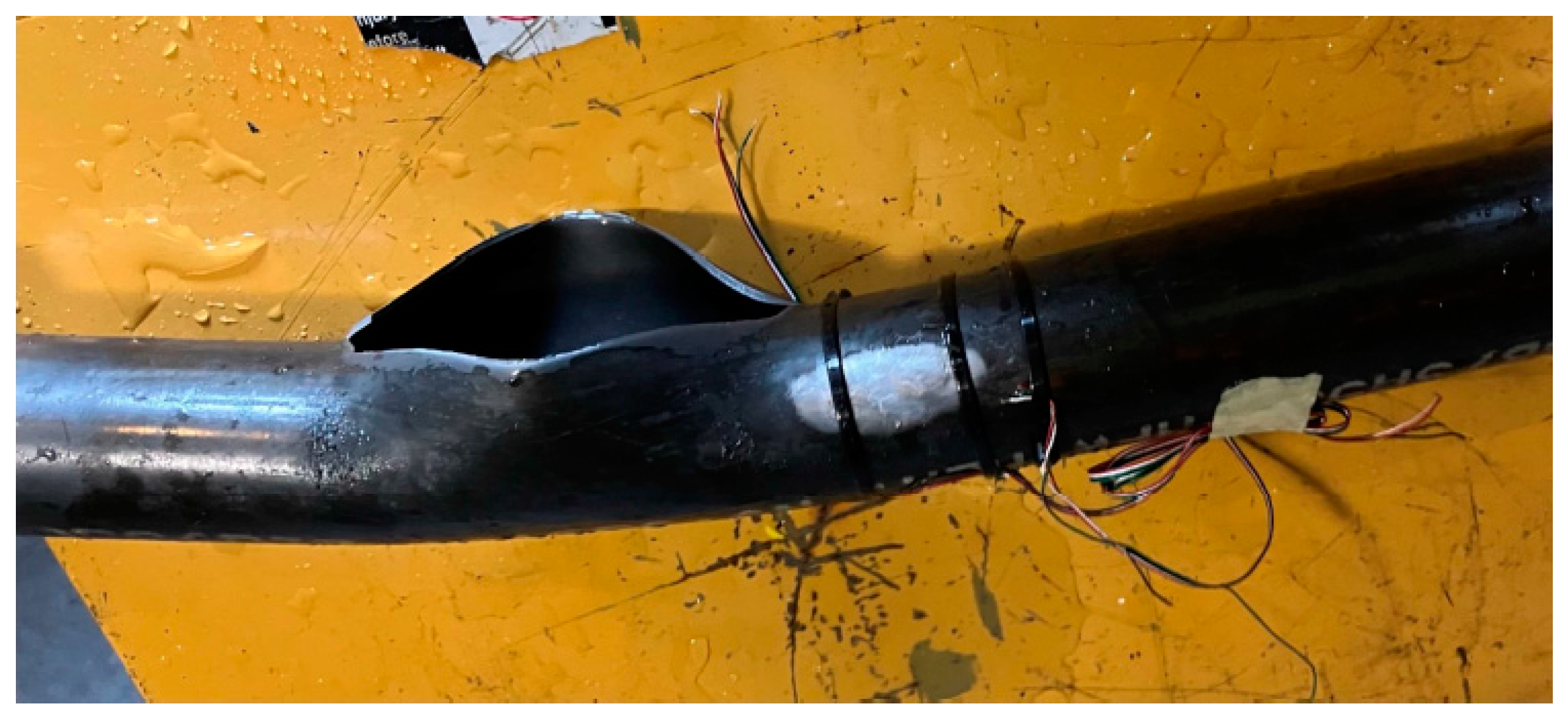
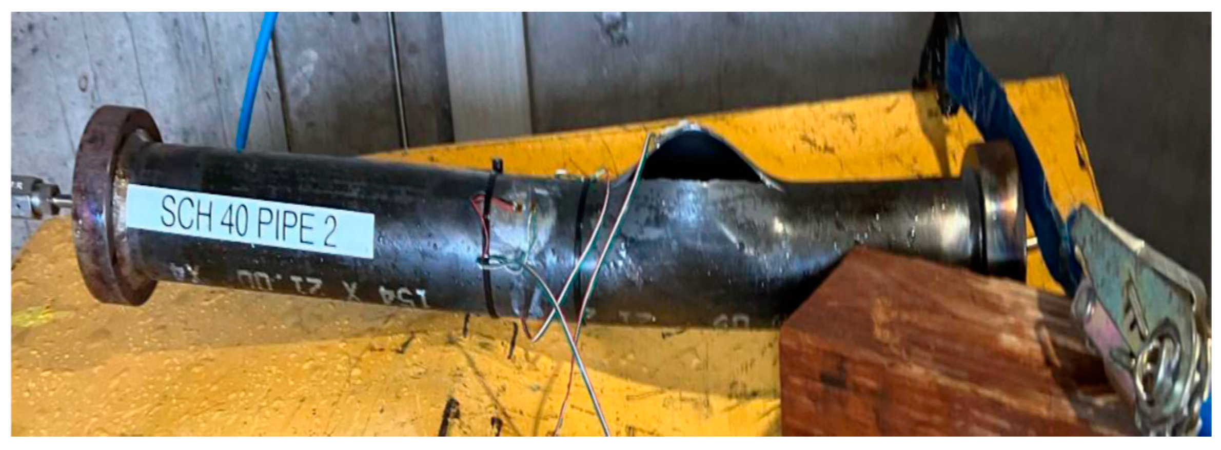
  • For SCH-40 Pipe 1, bursting occurred in the pipe body close to the middle of the pipe, and burst pressure was achieved at 9646.4 psig (66.5 MPa). The pipe failure was ideally located in the pipe body for this burst test.
  • For SCH-40 Pipe 2, likewise, bursting occurred in the pipe body, near the middle of the pipe, and burst pressure was measured as 9634.95 psig (66.4 MPa). The pipe failure was also ideally located in the pipe body for this burst test.
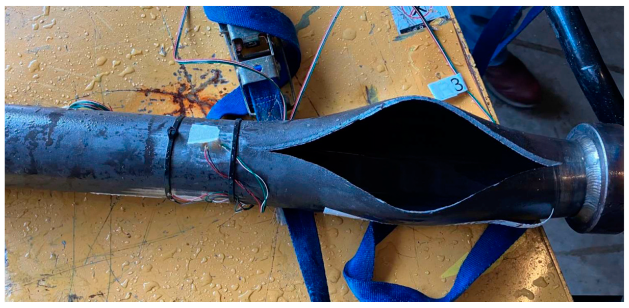
  • For SCH-80 Pipe 1, bursting occurred in the pipe body close to one end of the pipe, and burst pressure was measured as 14,369.81 psig (99.1 MPa). The pipe failure was located in the pipe body but close to the pipe end for this burst test.
  • For SCH-80 Pipe 2, the test result was questionable. The pipe failure occurred in the seam weld of the test pipe. After the seam weld ruptured, the crack propagated into the end weld. The failure pressure was achieved at 14,110 psig (97.3 MPa). This seam weld failure pressure may be less than that for the pipe body failure.
  • For SCH-160 Pipe 1, the failure was present around the high-pressure fitting weld, and pressurization was not possible due to leaking. Thus, no burst datum was recorded.
  • For SCH-160 Pipe 2, the failure occurred at the end cap weld. This demonstrated that the end cap welds used in this work may be inappropriate and not have the sufficient strength required for thick-walled pipes. Accordingly, stronger end cap welds are needed. The weld failure occurred at 24,887 psig (171.6 MPa). This weld failure pressure may be less than that for the pipe body failure.

3.4. Comparison of Measured and Predicted Burst Pressures

With the measured material properties given in Table 1 for the Grade B carbon steel pipes, the Zhu–Leis flow solution of burst pressure is predicted from Equation (10) for each burst test pipe. Table 2 summarizes the measured and predicted burst pressures for all the burst test pipe specimens. The relative errors of the Zhu–Leis flow solution for thick-walled pipes compared to the measured burst data are also given in this table. The first three burst test pipes failed in the pipe body, and the Zhu–Leis flow solution matches well with the measured burst data with a small error of less than 3%. The other two burst test pipes failed either at the seam weld or at the end cap weld, and thus, their measured failure pressures may be less than the real burst pressures if the pipes fail in the pipe body. Even in this situation, the Zhu–Leis flow solution still agrees fairly well with the measured failure pressure data with a light overprediction and a small error of less than 5%.
Figure 9 further compares all the measured burst test data with the burst pressures predicted from Equation (10) for the Tresca, von Mises, and Zhu–Leis yield criteria, respectively.
This figure shows that the von Mises flow solution provides an upper bound prediction within +10% of the measured burst pressure data, the Tresca flow solution provides a lower bound prediction within −10% of the measured burst pressure data, and the Zhu–Leis flow solution provides a more accurate, averaged prediction of burst pressure for all five burst test pipes compared to the measured burst pressure data. In summary, the comparisons in Table 1 and Figure 9 demonstrate that the von Mises flow solution is an upper bound prediction, the Tresca flow solution is a lower bound prediction, and the Zhu–Leis flow solution is a more accurate burst prediction for thick-walled pipes.

4. Additional Experimental Validations

4.1. Validation for Thin-Walled Line Pipes

More than 100 full-scale burst test data, as collected by Zhu and Leis [9,15] for thin-walled line pipes in a wide range of pipeline steels ranging from Grade B to X120, can be utilized here to validate the exact burst pressure models in Equation (10) that were developed for thick-walled cylindrical shells under internal pressure. As a result, the same observations and conclusions obtained for the thin-walled burst pressure models in Equation (5) are obtained again for the thick-walled burst pressure models in Equation (10). That is, the Tresca flow solution determines a lower bound prediction, the von Mises flow solution determines an upper bound prediction, and the Zhu–Leis flow burst pressure solution determines a more accurate, averaged prediction of burst pressure data.

4.2. Validation for Thick-Walled Tubes

Faupel [28] published around 100 burst pressure test data for small-diameter, thick-walled pressure tubes for a variety of ductile metals, including carbon steels, stainless steels, low alloy steels, weld steels, and other metals. The pressure tube specimens were very thick, and their D/t ratios were very small, within 2.4 < D/t < 4.7. From these burst tube tests, 30 burst test data for low alloy steels were selected and utilized in this section for evaluating the burst prediction models in Equation (10). These low alloy steels have different yield strengths, from 244 to 1076 Mpa, and different ultimate tensile strengths, from 459 to 1119 MPa. The strain hardening exponent n is less than 0.25 for these steels.
Figure 10 compares the burst pressure predictions from the six representative models with the burst test data obtained by Faupel [28] for the thick-walled pressure tubes. As is evident from Figure 10, the Mises strength solution is an absolute upper bound prediction, and the Tresca strength solution is an overall averaged prediction. The von Mises flow solution predicts an improved upper bound result, the Tresca flow solution predicts an improved lower bound result, and the Zhu–Leis flow solution predicts a more accurate, averaged result of all the burst pressure data. In addition, the approximate Svensson model overpredicts a result for all the burst test data.
Figure 11 directly compares the burst pressures predicted from the three flow burst models with the burst test data for the thick-walled pressure tubes. From this figure, it is observed that the von Mises flow solution overpredicts the burst data and fits only about 10% of the test data, the Tresca flow solution underpredicts the burst data and fits about 30% of the test data, and the Zhu–Leis flow solution predicts an averaged result and fits about 60% of the test data. Therefore, it is concluded that the Zhu–Leis flow solution is the best burst prediction model and is recommended for use in a pressure vessel design.

5. Conclusions

This paper briefly discussed the six representatives of burst pressure prediction models for thick-walled pipes or cylindrical vessels, including the Tresca strength solution, the von Mises strength solution, the Svensson approximate solution, and three newly proposed exact solutions for thick-walled pipes in terms of the Tresca, von Mises and Zhu–Leis yield criteria. To validate the newly developed Zhu–Leis flow solution for thick-walled pressure vessels, a set of pressure burst tests was conducted on API 5L Grade B carbon steel pipes. The pipe specimens have a nominal diameter of 2.375 inches (60.33 mm) and three nominal wall thicknesses of 0.154 inches (3.91 mm), 0.218 inches (5.54 mm), and 0.344 inches (8.74 mm). Comparisons of the burst pressure predictions with the burst test data obtained in this work and collected from the literature all validated the accuracy of the newly developed Zhu–Leis flow solution for both thin and thick-walled pipes or cylinders. Primary results and conclusions were obtained as:
(1)
Three exact flow solutions of burst pressure based on the Tresca, von Mises and Zhu–Leis yield criteria are functions of UTS, n, and ln(Do/Di) for thick-walled pipes. Among them, the Tresca flow solution is a lower bound prediction of burst data, the von Mise flow solution is an upper bound prediction, and the Zhu–Leis flow solution is an averaged prediction.
(2)
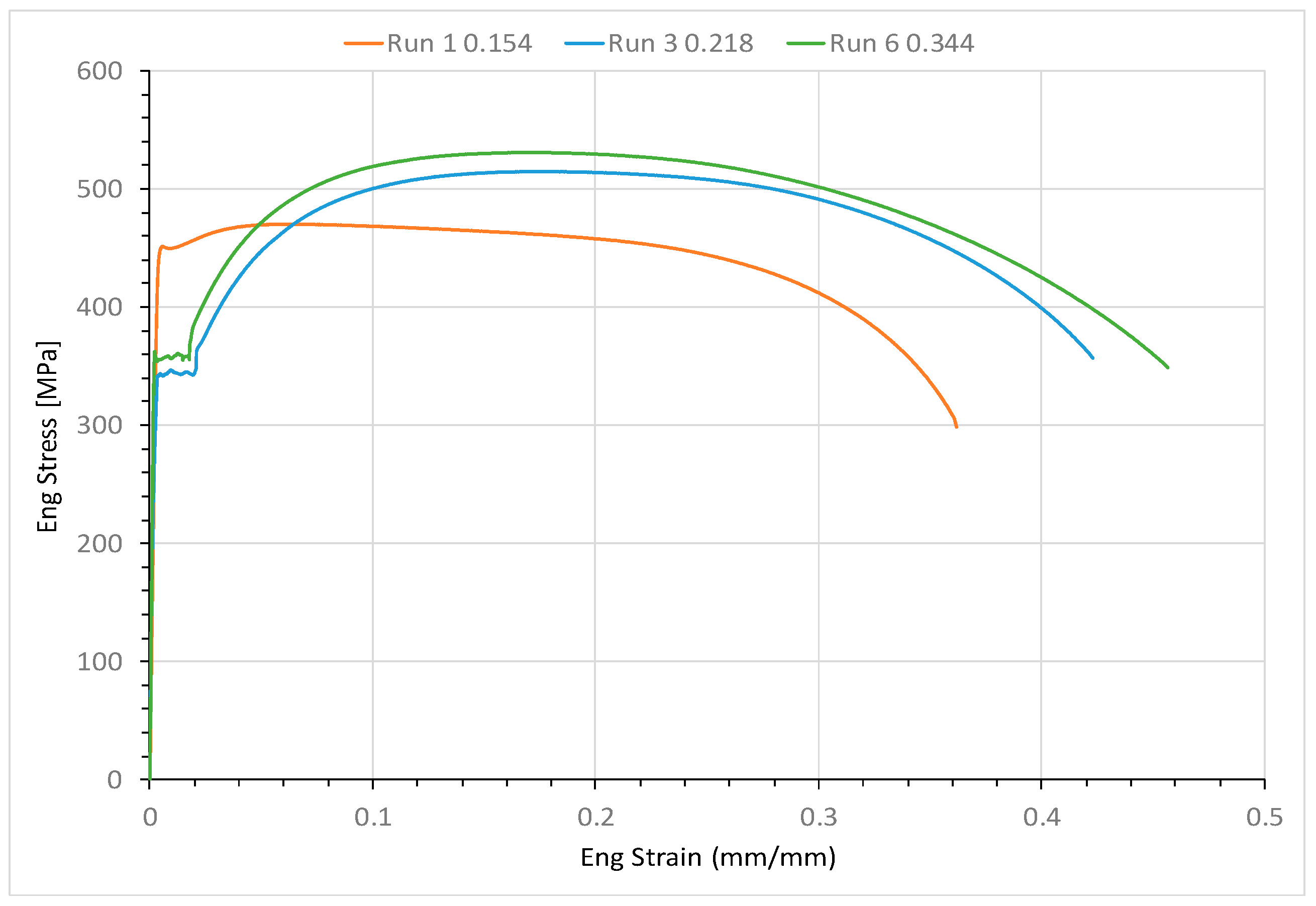
For three Grade B carbon steel pipes, the materials’ mechanical properties were measured from the uniaxial tensile tests. The measured stress–strain curves were similar for the two thicker pipes (i.e., SCH-80 and SCH-160), but differed for the thinner one (i.e., SCH-40). The reason for the differences between the same purchased pipes is unknown. The possible factors may include (1) these same labeled Grade B steels were manufactured by different manufacturing processes, and (2) small variations in the chemical compositions were possible for these steels.
(3)
The “air-over-water” pressurization process was successfully utilized in all the pressure burst tests at SRNL. Both monotonical loading and multi-step loading approaches were applied to the pipe pressure burst tests. The slow multi-step loading approach showed up as a more reasonable procedure for a pressure burst test.
(4)
The outside circular welding process used to join the end plate caps for the pressure test pipe specimens worked well for the thinner walls of the pipes (SCH-40 and SCH-80) but was inappropriate for thick walls (SCH-160). In the latter case, circular welds failed first due to insufficient weld strength. Accordingly, the single V-groove welding process is suggested for joining the end plate caps onto the pipe specimen to avoid a circumferential crack forming inside of the pipe at each end plate cap.
(5)
The burst pressure test data measured at SRNL and obtained from the literature all validated that the Zhu–Leis flow solution is the best burst prediction model for both thin and thick-walled pipes, whereas the von Mises flow solution predicts an upper bound result, and the Tresca flow solution predicts a lower bond result for both thin and thick-walled pipes.
In summary, the experimental burst test data and the evaluation results obtained in this work provide a sound technical base for the pressure vessel and pipeline industry to use the newly developed exact burst pressure solutions for better structural design and integrity management of thick-walled pipelines and pressure vessels.

Funding

This research received no external funding.

Institutional Review Board Statement

Not applicable.

Informed Consent Statement

Not applicable.

Data Availability Statement

The original contributions presented in this study are included in the article. Further inquiries can be directed to the corresponding author.

Acknowledgments

The pressure burst tests were conducted by Will Baggett, Michael Restivo, and Greg Sides at the Savannah River National Laboratory (SRNL). The tensile tests were carried out by Tim Krentz at SRNL. Bruce Wiersma supported the steel pipe purchase. Martin Johnson led specimen machining and test pipe cap welding. This work was sponsored by the U.S. DOE Laboratory Directed Research and Development (LDRD) program through LDRD projects 2022-00077 and 2024-00146 within SRNL. This document was prepared in conjunction with work accomplished under Contract No. 89303321CEM000080 with the U.S. Department of Energy (DOE) Office of Environmental Management (EM).

Conflicts of Interest

The author declares no conflict of interest.

Appendix A. Exact Burst Pressure Solutions for Thick-Walled Cylindrical Shells

Based on the von Mises flow theory of plasticity, in 1958, Svensson [14] obtained an implicit integral equation for calculating the burst pressure of thick-walled cylindrical shells subject to internal pressure as follows:
P b = σ 0 ε 1 ε 2 ε n 1 e x p ( 3 ε ) d ε
where Pb is the burst pressure of the vessel, σ0 is a material strength parameter defined as σ 0 = σ u t s ( e n ) n , σuts is the UTS of the material, n is the strain hardening exponent of the material, and ε is a von Mises equivalent strain variable. ε1 and ε2 are two critical strain parameters at pressure bursting that are functions of n and Do/Di. Svensson [14] realized that the implicit integral Equation (A1) is not suitable for design calculations and thus developed a set of tabular data solutions and an approximate burst pressure solution, as given in Equation (9). Recently, API 579-1/ASME FFS-1 2021 Edition [33] recommends this integral Equation (A1) proposed by Svensson [14] for estimating the burst pressure of cylindrical pressure vessels.
Recently, Zhu et al. [22,23] revisited Svensson’s theoretical work [14] and obtained the same burst pressure integral Equation (A1) based on the von Mises theory of plasticity. With the use of the Bernoulli numbers, these authors were able to analytically calculate the integral Equation (A1) and obtained a general solution of burst pressure in a function of power series for thick-walled cylinders in reference to the Tresca, von Mises, and Zhu–Leis theories of plasticity, as follows:
P b = σ 0 C 2 ε 2 n 1 n + ε 2 C n + 1 i = 1 1 i 1 B i 2 i ! 2 C ε 2 2 i 2 i + n   σ 0 C 2 ε 1 n 1 n + ε 1 C n + 1   i = 1 1 i 1 B i 2 i ! 2 C ε 1 2 i 2 i + n
where C is a known constant defined by Equation (6), and Bi (i = 1, 2, …, ∞) are the Bernoulli numbers that are determined. The first five Bernoulli numbers are given as: B 1 = 1 6 , B 2 = 1 30 , B 3 = 1 42 , B 4 = 1 30 , and B 5 = 5 66 . As C = 2/√3, Equation (A2) is the same as that obtained by Svensson [14] for the von Mises yield criterion. For a specific thick-walled pressure vessel, the values of UTS, n, and Do/Di ratio are known, and the critical strains ε1 and ε2 can be solved first. The exact burst pressure solution is then determined from Equation (A1) using a numerical integration technique, or directly calculated from Equation (A2) using the power series solution of burst pressure.
Figure A1 shows the variation of the Zhu–Leis burst pressure solution (i.e., C = ½ + 1/√3) calculated directly from Equation (A2) and normalized using the material strength parameter ( P b σ 0 ) with ln D o D i for five given values of n = 0, 0.05, 0.10, 0.15, and 0.20. The Zhu–Leis flow solution of burst pressure in Equation (10) is also included in this figure for comparison. The results show that the Zhu–Leis flow solution in Equation (10) agrees well with the exact burst pressure values calculated from Equation (A1) or (A2) for all n values. This infers that the Zhu–Leis flow solution in Equation (10) is an exact solution of burst pressure for thick-walled cylindrical vessels when the Zhu–Leis yield criterion is used.
Figure A1. Normalized Zhu–Leis burst pressure (Pb0) against ln(Do/Di) for the specific n values.
Applmech 06 00020 g0a1
Recently, different investigators performed burst pressure analyses for thick-walled pressure vessels, including small tubes and offshore used casings. For example, Deng et al. [34] obtained a comparable burst pressure solution for thick-walled tubes using the through-wall yield analysis approach based on the bi-linear strain hardening law for the material, and Shi et al. [35] developed a finite element calculation method for determining the ultimate burst pressure for thick-walled tubes.

Appendix B. Burst Testing Pipe Specimen Design Drawing

This appendix provides the details of the burst test pipe specimen design drawing. Circular steel plates with a diameter of 3.5 inches (88.9 mm) and a wall thickness of 1 inch (25.4 mm) were cut and welded to the end of each pipe to ensure the pressure pipes burst preferential to the end fitting, as shown in Figure A2. The high-pressure pipe fittings were also fitted to the middle of each plate.
Figure A2. Pressure pipe specimen design drawing.
Applmech 06 00020 g0a2

Appendix C. Failure Appearance of Pressure Burst Test Pipes

This appendix reports the failure appearance of pressure burst tested pipes after bursting. For the nominal wall thickness of 0.154 inches (3.91 mm), Figure A3 shows the failure appearance of SCH-40 Pipe 1 after bursting, and Figure A4 shows the failure appearance of SCH-40 Pipe 2 after bursting. For the nominal wall thickness of 0.218 inches (5.54 mm), Figure A5 shows the failure appearance of SCH-80 Pipe 1 after bursting, and Figure A6 shows the failure appearance of SCH-80 Pipe 2 after bursting. For the nominal wall thickness of 0.344 inches (8.74 mm), Figure A7 shows the failure appearance of SCH-160 Pipe 2 after bursting.
Figure A3. Schedule 40 Pipe 1 after bursting.
Applmech 06 00020 g0a3
Figure A4. Schedule 40 Pipe 2 after bursting.
Applmech 06 00020 g0a4
Figure A5. Schedule 80 Pipe 1 after bursting.
Applmech 06 00020 g0a5
Figure A6. Schedule 80 Pipe 2 after bursting.
Applmech 06 00020 g0a6
Figure A7. Schedule 160 Pipe 2 after bursting.
Applmech 06 00020 g0a7

References

  1. Zhu, X.K. Strength criteria versus plastic flow criteria used in pressure vessel design and analysis. J. Press. Vessel. Technol. 2016, 138, 041402. [Google Scholar] [CrossRef]
  2. Hamgung, I.; Giang, N.H. Investigation of burst pressures in PWR primary pressure boundary components. Nucl. Eng. Technol. 2016, 48, 236–245. [Google Scholar] [CrossRef]
  3. Lyons, C.J.; Race, J.M.; Change, E.; Cosham, A.; Wetenhall, B.; Barnett, J. Validation of the NG-18 equations for thick-walled pipelines. Eng. Fail. Anal. 2020, 112, 104494. [Google Scholar] [CrossRef]
  4. Kadam, M.; Balamurugan, G.; Bujurke, A.A.; Joshi, K.M. Finite element prediction of static burst pressure in closed thick-walled unflawed cylinders of different diameter ratios. Procedia Eng. 2017, 173, 577–594. [Google Scholar] [CrossRef]
  5. Hamada, M.; Yokoyama, R.; Kitagawa, H. An estimation of maximum pressure for a thick-walled tube subjected to internal pressure. Int. J. Press. Vessel. Pip. 1986, 22, 311–323. [Google Scholar] [CrossRef]
  6. Christopher, T.; Rama Sarma, B.S.; Govinda Potti, P.K.; Rao, B.N. A comparative study on failure pressure estimation of unflawed cylindrical vessels. Int. J. Press. Vessel. Pip. 2002, 79, 53–66. [Google Scholar] [CrossRef]
  7. Krishnaveni, A.; Christopher, T.; Jeyakumar, K.; Jebakani, D. Probabilistic failure prediction of high strength steel rocket motor cases. J. Fail. Anal. Prev. 2014, 14, 478–490. [Google Scholar] [CrossRef]
  8. Law, M.; Bowie, G. Prediction of failure strain and burst pressure in high yield to-tensile strength ratio linepipe. Int. J. Press. Vessel. Pip. 2007, 84, 487–492. [Google Scholar] [CrossRef]
  9. Zhu, X.K.; Leis, B.N. Evaluation of burst pressure prediction models for line pipes. Int. J. Press. Vessel. Pip. 2012, 89, 85–97. [Google Scholar] [CrossRef]
  10. Wang, H.; Zheng, T.; Sang, Z.; Krakauer, B.W. Burst pressures of thin-walled cylinders constructed of steel exhibiting a yield plateau. Int. J. Press. Vessel. Pip. 2021, 193, 104483. [Google Scholar] [CrossRef]
  11. Sun, M.; Chen, Y.; Zhao, H.; Li, X. Analysis of the impact factor of burst capacity models for defect-free pipelines. Int. J. Press. Vessel. Pip. 2022, 200, 104805. [Google Scholar] [CrossRef]
  12. Stewart, G.; Klever, F.J. An analytical model to predict the burst capacity of pipelines. In Proceedings of the International Conference of Offshore Mechanics and Arctic Engineering, Houston, TX, USA, 27 February–3 March 1994; American Society of Mechanical Engineers: New York, NY, USA, 1994; Volume V: Pipeline Technology, pp. 177–188. [Google Scholar]
  13. Cooper, W.E. The significance of the tensile test to pressure vessel design. Weld. J.-Weld. Res. Suppl. 1957, 36, 49s–56s. [Google Scholar]
  14. Svensson, N.L. The bursting pressure of cylindrical and spherical vessels. J. Appl. Mech. 1958, 25, 89–96. [Google Scholar] [CrossRef]
  15. Zhu, X.K.; Leis, B.N. Average shear stress yield criterion and its application to plastic collapse analysis of pipelines. Int. J. Press. Vessel. Pip. 2006, 83, 663–671. [Google Scholar] [CrossRef]
  16. Zimmermann, S.; Hohler, S.; Marewski, U. Modeling ultimate limit states on burst pressure and yielding of flawless pipes. In Proceedings of the 16th Biennial Pipeline Research Joint Technical Meeting, Canberra, Australia, 16–19 April 2007. Paper 13. [Google Scholar]
  17. Knoop, F.M.; Flaxa, V.; Zimmermann, S.; Grob-Weege, J. Mechanical properties and component behavior of x80 helical seam welded large diameter pipes. In Proceedings of the 8th International Pipeline Conference, Calgary, AB, Canada, 27 September–1 October 2010. [Google Scholar]
  18. Bony, M.; Alamilla, J.L.; Vai, R.; Flores, E. Failure pressure in corroded pipelines based on equivalent solutions for undamaged pipe. J. Press. Vessel. Technol. 2010, 132, 051001. [Google Scholar] [CrossRef]
  19. Zhou, W.; Huang, G. Model error assessment of burst capacity models for defect-free pipes. In Proceedings of the 9th International Pipeline Conference, Calgary, AB, Canada, 24–28 September 2012. [Google Scholar]
  20. Seghier, M.E.A.B.; Keshtegar, B.; Elahmoune, B. Reliability analysis of low, mid and high-grade strength corroded pipes based on plastic flow theory using adaptive nonlinear conjugate map. Eng. Fail. Anal. 2018, 90, 245–261. [Google Scholar] [CrossRef]
  21. Zhu, X.K.; Wiersma, B.; Johnson, W.R.; Sindelar, R. Burst pressure solutions of thin and thick-walled cylindrical vessels. J. Press. Vessel. Technol. 2023, 145, 044202. [Google Scholar] [CrossRef]
  22. Zhu, X.K. Exact solution of burst pressure for thick-walled pipes using the flow theory of plasticity. Int. J. Mech. Sci. 2023, 259, 108582. [Google Scholar] [CrossRef]
  23. Zhu, X.K.; Wiersma, B.; Johnson, W.R.; Sindelar, R. Exact solutions of burst pressure for thick-walled cylinders in power-law strain hardening steels. Int. J. Press. Vessel. Pip. 2023, 206, 105053. [Google Scholar] [CrossRef]
  24. Zhu, X.K. Recent advances in corrosion assessment models for buried transmission pipelines. CilvilEng 2023, 4, 391–425. [Google Scholar] [CrossRef]
  25. Bhardwaj, U.; Teixeira, A.P.; Soares, C.G. Burst strength assessment of X100 to X120 ultra-high strength corroded pipes. Ocean Eng. 2021, 241, 110004. [Google Scholar] [CrossRef]
  26. Amaya-Gomez, R.; Sanchez-Silva, M.; Bastidas-Arteaga, E.; Schoefs, F.; Munoz, F. Reliability assessments of corroded pipelines based on internal pressure—A review. Eng. Fail. Anal. 2019, 98, 190–214. [Google Scholar] [CrossRef]
  27. Bhardwaj, U.; Teixeira, A.P.; Soares, C.G. Uncertainty quantification of burst pressure models of corroded pipelines. Int. J. Press. Vessel. Pip. 2020, 188, 104208. [Google Scholar] [CrossRef]
  28. Faupel, J.H. Yield and bursting characteristics of heavy-wall cylinders, Transaction of ASME. J. Fluid Eng. 1956, 78, 1031–1064. [Google Scholar]
  29. Faupel, J.H.; Furbeck, A.R. Influence of residual stress on behavior of thick-wall closed-end cylinders. Trans. ASME J. Fluid Eng. 1953, 75, 345–354. [Google Scholar] [CrossRef]
  30. API 5L; Specification for Line Pipe. American Petroleum Institute: Washington, DC, USA, 2013.
  31. Baggett, H.W.; Restivo, M.L. Summary Report of LDRD Burst Pipe Testing; Savannah River National Laboratory: Aiken, SC, USA, 2022.
  32. ASTM E8/E8M-21; Standard Test Methods for Tension Testing of Metallic Materials. American Society for Testing and Materials International: West Conshohocken, PA, USA, 2021.
  33. API 579-1/ASME FFS-1 2021 Edition; Fitness-For-Service. The American Petroleum Institute and The American Society of Mechanical Engineers: Washington, DC, USA, 2021.
  34. Deng, K.; Peng, Y.; Liu, B.; Lin, Y.; Wang, J. Through-wall yield ductile burst pressure of high-grade steel tube and casing with and without corroded defect. Mar. Struct. 2021, 76, 102902. [Google Scholar]
  35. Shi, J.; Zhang, Q.; Lian, Z.; Ding, L.; Wan, Z. A calculation method for ultimate and allowable loads in high-pressure thick-walled worn casing. Ocean Eng. 2024, 313, 119448. [Google Scholar] [CrossRef]
Figure 1. Comparison of four geometry terms of ln(Do/Di), 2t/Dm, 2t/Do, and 2t/Di.
Applmech 06 00020 g001
Figure 2. API 5L Grade B black carbon steel pipe.
Applmech 06 00020 g002
Figure 3. Tensile test specimens.
Applmech 06 00020 g003
Figure 4. Tensile specimen fixture, extensometer, and broken specimen.
Applmech 06 00020 g004
Figure 5. Engineering stress–strain curves of the three Grade B carbon steel pipes.
Applmech 06 00020 g005
Figure 6. Pressure burst test setup for SCH-40 Pipe 1.
Applmech 06 00020 g006
Figure 7. Pressure-time records for SCH-40 Pipe 1 burst test.
Applmech 06 00020 g007
Figure 8. Pressure-time records for the SCH-40 Pipe 2 burst test.
Applmech 06 00020 g008
Figure 9. Comparison of measured and predicted burst pressures.
Applmech 06 00020 g009
Figure 10. Variations of measured and predicted burst pressures with strain hardening exponent n for the thick-walled tubes.
Applmech 06 00020 g010
Figure 11. Comparison of predicted and measured burst pressures for the thick-walled tubes.
Applmech 06 00020 g011
Table 1. Mechanical properties of three carbon steels.
SCHYS (MPa)YS (ksi)UTS (MPa)UTS (ksi)nElon
SCH-4045065.347068.20.06237%
SCH-8034249.651574.70.16143%
SCH-16035651.653177.00.15646%
Table 2. Measured and predicted burst pressures of all burst test pipes.
Pipe #Failure TypeMeasured Burst Pb, Psi (MPa)Zhu–Leis Bust Pb, Psi (MPa)Relative Error (%)
SCH-40, Pipe 1Body burst9646.4 (66.5)9817 (67.7)1.76
SCH-40, Pipe 2Body burst9634.95 (66.4)9817 (67.7)1.89
SCH-80, Pipe 1Body burst14,369.81 (99.1)14,774 (101.9)2.81
SCH-80, Pipe 2Seam failure14,110.03 (97.3)14,774 (101.9)4.71
SCH-160, Ppe 1fitting leaksN/A25,768 (177.7)N/A
SCH-160, Pipe 2Weld failure24,886.65 (171.6)25,768 (177.7)3.54
Disclaimer/Publisher’s Note: The statements, opinions and data contained in all publications are solely those of the individual author(s) and contributor(s) and not of MDPI and/or the editor(s). MDPI and/or the editor(s) disclaim responsibility for any injury to people or property resulting from any ideas, methods, instructions or products referred to in the content.

