Article

HDPE Properties Evaluation via Instrumented Indentation: Experimental and Computer Simulation Approach

by
Anna Aleksandrovna Vinogradova
1,
Kirill Valerievich Gogolinskiy
2,
Kirill Igorevich Doronin
1,
Ekaterina Konstantinovna Shchiptsova
1,* and
Alena Vadimovna Melnikova
3
1
Department of Metrology, Instrumentation and Quality Management, Empress Catherine II Saint Petersburg Mining University, 199106 Saint Petersburg, Russia
2
National Research Center “Kurchatov Institute”—PNPI, 188300 Gatchina, Russia
3
Department of Theoretical and Applied Metrology, The D.I. Mendeleev All-Russian Institute for Metrology (VNIIM), 190005 St. Petersburg, Russia
*
Author to whom correspondence should be addressed.
Appl. Mech. 2025, 6(2), 29; https://doi.org/10.3390/applmech6020029
Submission received: 5 March 2025 / Revised: 4 April 2025 / Accepted: 16 April 2025 / Published: 18 April 2025

Abstract

:
The paper analyzes the process of indentation of polymeric materials with a spherical indenter. The loading diagrams P(h) obtained experimentally and by means of finite element method (FEM) are analyzed. The material under study was high-density polyethylene (HDPE) of PE100 grade, taken from a pipeline for gas distribution systems. The aim of the work was to determine the parameters of the computer model, taking into account hardening and creep processes when verifying P(h) diagrams with experimental studies. The influence of variation of the parameters of the calculation formulas on the reliability of the simulation results was analyzed. The results of the calculation of mechanical properties of material on the basis of P(h) diagrams by the Oliver–Pharr method for model and experimental diagrams were compared. The possibility of using computer modeling for the analysis of instrumented indentation processes is demonstrated, since the results revealed the convergence of the elastic modulus of 1078 GPa for FEM and 1083 GPa for the experiment. The conformity of the Oliver–Pharr method for determining the contact depth is also shown, which differed from the model geometry by only 2.3%. Simulation of the indentation process using the Norton model via FEM, as well as determining the parameters of the material deformation function while taking creep into account, makes it possible to describe the process of contact interaction and shows good agreement with experimental data.

1. Introduction

Polymer materials have recently occupied one of the leading positions among structural materials and are widely used in various industries due to their outstanding mechanical properties, resistance to chemical influences, and durability [1].
In recent years, instrumented indentation (II) has proven itself as a promising method for studying the mechanical characteristics of polymers [2]. During indentation, this method allows one to evaluate the applied load and the penetration depth at each moment of time, which makes it possible to determine the mechanical properties with high accuracy using various methods. A significant advantage of the instrumented indentation method over all other methods of hardness measurement is the ability to determine the elastic (Young’s) modulus, coefficient of recovery, and creep of the material under load [3]. Creep is one of the most important properties in the study of plastics, since the time dependence of the material deformation can be used in simulation for more accurate prediction of properties and, therefore, increasing the reliability of products.
The instrumented indentation method has been used to study various types of plastic and materials made from this plastic, including: polyurethane [4]; various composite materials, fiber-reinforced plastics [5]; polyoxymethylene (POM) [6]; elastomers [7]; polyethylene terephthalate (PET), used in various industries: from application in the packaging and fiber industry to use as substrates in photovoltaic modules [8]; polymethyl methacrylate (PMMA) [9]; ultra-high molecular weight polyethylene (UHMWPE) [10]; reinforced polymer composites [11], self-healing epoxy resins [12] etc. The instrumented indentation method makes it possible to study the properties of polymer surfaces [13], as well as coatings and films created on the basis of polymer materials [14]. It is used to evaluate the characteristics of high-density polyethylene pipelines intended for transportation of natural gas [15] and hydrogen [16], as well as to study welded joints of polyethylene gas pipelines [17,18]. This opens up prospects for assessing the fracture resistance of engineering polymers under various operating conditions. The instrumented indentation method is also relevant because it is a non-destructive method for monitoring mechanical properties, which allows the identification of damage in materials and structures without destroying them, detecting potential problems at an early stage, which is important for ensuring safety in areas such as construction, aviation, oil and gas industry, and energy [19,20].
In the presented work, II was used to study the properties of high-density polyethylene (HDPE), intended for the production of polyethylene gas pipelines. Polyethylene gas pipelines have become an integral part of modern gas transportation systems, solving one of the main problems of increasing energy efficiency in the oil and gas industry [21,22]. The use of such gas pipelines instead of metal ones leads to simplification of their installation due to weight reduction, reduction of hydraulic losses and power consumption for transporting materials, increased pipe capacity, and increased service life. However, over time, the material can change its mechanical properties and become less durable [23,24,25], which can lead to gas leaks and accidents [26]. Therefore, to ensure the reliability and durability of gas pipelines, it is important to study the mechanical properties of these materials, which determine their behavior under various operating conditions.
There are several standardized methods for determining the mechanical properties of polymers that are widely used in research and industry. Such pipe quality control methods involve testing on full-size samples that determine all the properties of the pipe. These tests are carried out in accordance with ISO 6259-1:2015 [27] and are used for quality control of new pipes. To carry out diagnostics of existing gas pipelines using these methods, it is necessary to stop the operating gas pipeline, cut out a part of the pipe, and use it for testing. That is why the task of developing a technique for monitoring the parameters of the pipe material on small-sized samples is relevant. The instrumented indentation test can become an alternative to standardized methods.
When studying polymeric materials, a comprehensive approach is needed in terms of determining mechanical properties [28]. One way is to model objects or processes using the finite element method (FEM) [29]. The modeling capabilities can significantly expand the understanding of the processes and phenomena occurring in the studied systems or objects [30,31,32] and describe control procedures [33,34,35]. General approaches to II simulation can be found in [36,37], but the applicability of the finite element method is wider in terms of combining indentation and the finite element method for polymers [38]. Therefore, the task of determining plastic properties using yield parameters and calculation methods that affect the type of loading diagram and comparing the resulting models with experimental results is relevant.
There are numerous attempts to simulate the process of instrumented indentation of plastics using the finite element method. Existing works demonstrate simulation capabilities that make it possible to describe a complex of micromechanical properties in relation to HDPE, even when using Vickers indenters [39]. There are also works on simulation the process of HDPE indentation with flat tips [40,41]. Simulation also potentially allows one to determine the integral characteristics of the deformation of the entire test object—the pipe—as in [42]. In such cases, it is necessary to correctly describe the deformation, taking into account viscoelastic and viscoplastic models of polyethylene [43], also taking into account the test conditions [44]. The description of this deformation in HDPE simulations can be determined from empirical expressions [45,46] or by calculating the function parameters after mechanical tests [47,48]. Simulations that faithfully mirror the experimental conditions could minimize potential errors in real experiments by ensuring correlation between simulated and experimental results.
The overall goal of this work was to construct an adequate finite element model of II HDPE and establish the parameters of the hardening and creep functions for computer simulation of this process. In the future, it is planned to use the tested model and the obtained values to solve the II problem in a dynamic formulation similar to [49,50]. Indentation and simulation can also contribute to solving the inverse problem for describing creep [51,52]. Determination of creep deformation parameters can be used to assess the technical condition of an HDPE material [53,54]. The software COMSOL Multiphysics® 6.1 [55] was used for computational analysis in the simulation, taking into account the loading scheme during experimental tests.

2. Materials and Methods

2.1. Experimental Part
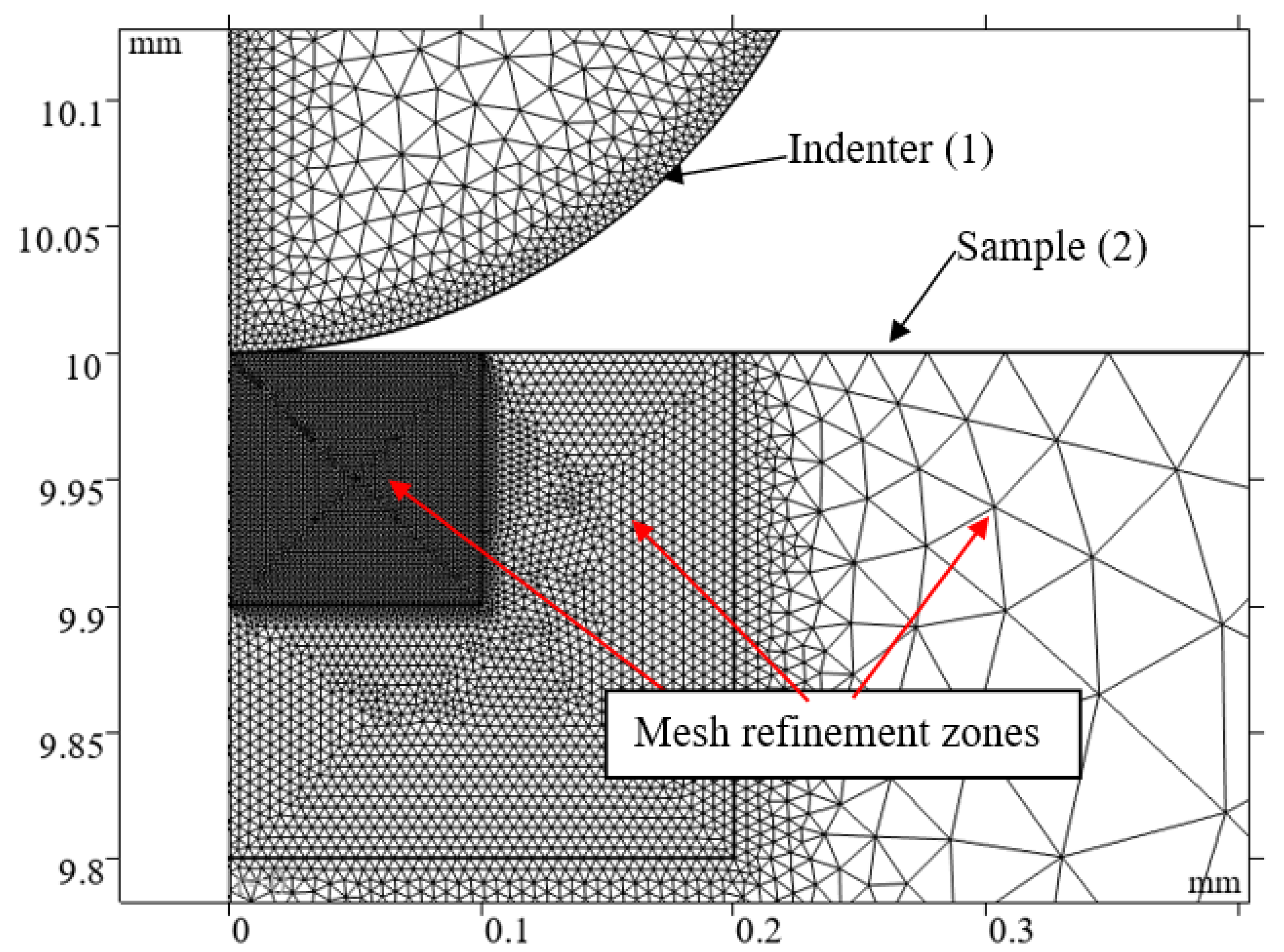
For a comprehensive assessment of mechanical properties, the instrumented indentation method was used, based on continuous recording of load and displacement during the indentation of a harder body into the material under study. The tests by the II method were carried out using the mechanical testing module of the nanohardness tester “Nanoscan-4D+” (manufacturer: FSBI “TISNCM”, Moscow, Russia). The test sample was cut from a pipe made of HDPE PE100, with a diameter of 110 mm and a wall thickness of 10 mm, and poured into a special compound so that the end cut of the pipe was accessible for research. Then, it was mechanically polished with abrasive paper and a muslin wheel using Dialux polishing paste (manufacturer: OSBORN, Haan, Germany) to a roughness value of Ra = 0.05 μm (Figure 1a).
The measurements by the II method were carried out at room temperature of 23 ± 2 °C. A spherical silicon carbide (SiC) tip with a radius of R = 250 μm was used as an indenter (Figure 1b). The calibration procedure of the device was carried out on a standard sample made of polycarbonate with assigned mechanical characteristics: hardness HIT = 0.21 ± 0.02 GPa, indentation Young’s modulus EIT = 3.0 ± 0.3 GPa). The following loading mode was determined for experimental studies by the II method, presented in Table 1. This mode provides a loading rate of 1.4 mN/s. The conditions and parameters of the tests corresponded to [56]. The sensitivity to the indentation size effect upon reaching such a load is insignificant and can be corrected [57,58].
The results of experimental studies were processed based on the Oliver–Pharr methodology [59] using the obtained indentation diagrams (Figure 2). The HIT indentation hardness was determined as the ratio of the maximum load to the projected contact surface area Ap = f(R, hc):
H I T = P m a x A p
To calculate the elastic modulus EIT, Expression (2) is used, taking into account the reduced elastic modulus Er (Expression (3)).
E I T = 1 ν s 2 1 E r 1 ν i 2 E i
E r = S π 2 A p
In Expressions (2) and (3), the values Ei of the indenter elastic modulus Ei, the Poisson’s ratio of the test material νs, and the Poisson’s ratio of the indenter material νi are constants. The contact stiffness parameter S is calculated taking into account the tangent in the area of the unloading stage:
S = P m a x h m a x h r
The value of the contact depth hc is calculated for further calculation of the contact surface area Ap, taking into account the correction factor ε = 0.75 for a spherical tip.
h c = h m a x ε h m a x h r
The simulation is carried out in an axisymmetric setting (Figure 3) relative to the symmetry axis z. The two main elements of the contact interaction process are indenter 1 and sample 2. When simulating quasi-static instrumented indentation, a radius of R = 250 μm is defined for a spherical indenter. This value corresponds to the radius of the spherical tip when conducting experimental studies using the II method.

2.2. Simulation

To solve the contact problem, the general definition of the Contact pair model is used. The contact method used is Augmented Lagrangian, the efficiency of which has been demonstrated in solving a similar problem [60,61]. The mesh for domains is specified based on the condition of the contact problem: the condition of the element sizes, in which the destination boundary must have twice as many elements as the source boundary. For both domains, a free triangular mesh with compaction in the contact boundary area was selected (Figure 3). The maximum element size at the indenter boundary was 0.5 μm, and at the sample boundary, it was 0.2 μm.
The basis for calculating the parameters of mechanical deformation during the interaction of domains in the used software COMSOL Multiphysics® 6.1 is the properties of their materials. For deformation problems in Solid Mechanics, such physical and mechanical properties as density ρ, elastic modulus E, and Poisson’s ratio of the material ν are used. The Plasticity module was used to solve the problem of plastic deformation. For the indenter body for static indentation, only linear deformations are allowed despite the possibility of specifying a non-deformable body [62]. The specified values of the basic mechanical properties are presented in Table 2. The support properties for HDPE are determined on the basis of works [63,64,65].
During the mechanical deformation of polyethylene, the effect of increasing resistance with increasing deformation is observed. Also, for the material under study (HDPE), creep processes are clearly manifested under the action of static load since, for thermoplastics, there are features of deformation after reaching the yield point [66] and deformation depends on load rate [67,68]. At the same time, work has already been carried out to take into account the strain hardening of polyethylene [69] and the strain rate [64]. To determine the process of creep effect during quasi-static indentation, Norton’s law for creep deformation εcr [55] was used.
f ( σ e ) = ε c r = A σ e σ r e f n
The function describes the change in the additional creep strain εcr at the moment of von Mises stress σe upon specified reference stress σref through the material constant A—creep rate coefficient and stress exponent n. The use of this function is justified by its application for modeling creep under tension in polymeric materials [64], as well as in indentation in general [70]. In this case, it is possible to use other models [71,72], but further research will be devoted to this issue. One of the objectives of the work is to determine the numerical values of the Norton model coefficients (A, n, σref) for the correct description of the change in properties. These parameters can be established after processing the tensile diagrams [47], but it is not always possible to conduct full-scale tests. The expression f(σe) from Formula (6) is used in the condition of nonlinear isotropic hardening described by the strain hardening function according to Equation (7) [47,55]:
h ( ε c e ) = m ε c e + ε s h i f t t r e f   f ( σ e ) m 1 m
The parameters of the hardening exponent m, equivalent creep strain shift εshift, and reference time tref are defined as constants equal to 1, 10−5, and 3600 s, respectively. The Time-Dependent step-by-step solution method was used to model the contact process. The solution method chosen was BDF (Backward Differentiation Formula), based on the fact that for each new step of the solution, information about the previous steps is also used. The standard MUMPS solver allows parallel solving of systems of linear algebraic equations generated in COMSOL.

3. Results

3.1. Experiment

The results of the experimental studies to determine the mechanical properties of the HDPE sample are presented in Table 3. The presented data correspond to 5 measurements and the calculated standard deviation (SD). The recovery coefficient rc defined as the ratio of the depth for plastic and elastic deformation rc = (hmaxhf)/hf. The reference result of the experiment is the value of the elastic modulus EIT = 1083 ± 4 MPa, hardness HIT = 14.09 ± 0.04 MPa. The determined value of the elastic modulus is within the range of values given in [65,73,74] and is also close to the value from [75]. At the same time, the hardness values may differ from those presented in the above-mentioned works, as well as in [76], due to the use of a different type of tip.

3.2. FEM Simulation

Based on the indentation diagrams obtained as a result of experimental studies, the validation of the computer model of the II process was carried out. In the process of simulation, the optimal parameters of the creep function were determined: A = 1.1 × 10⁻¹⁵, n = 6, σref = 0.1 MPa. With these values, the indentation diagram best correlates at the maximum indentation depth hmax with the diagram obtained in the experiment, which is demonstrated in Figure 4. The numerical values of the calculated mechanical properties according to the diagrams obtained in the modeling are presented in Table 4. The retraction part of the simulated indentation curve can have a slightly different angle from the experiment, which can also be noticed in [60]. The elastic properties of the model experiment (EIT = 1078 MPa) do not differ from those of the natural experiment (EIT = 1083 MPa). The elastic modulus of HDPE obtained by indentation may differ from that obtained by other testing methods, such as compression [77], and some works specify the elastic modulus of polyethylene in simulation as higher than 1.3 GPa [78].
The difference between the calculated mechanical properties in the simulation and experiment is demonstrated by the indentation hardness HIT (18.06 MPa vs. 14.06 MPa). This can be a consequence of the different contact area Ap, determined through the contact cross-section radius r according to the expression:
A p = π r 2

4. Discussion

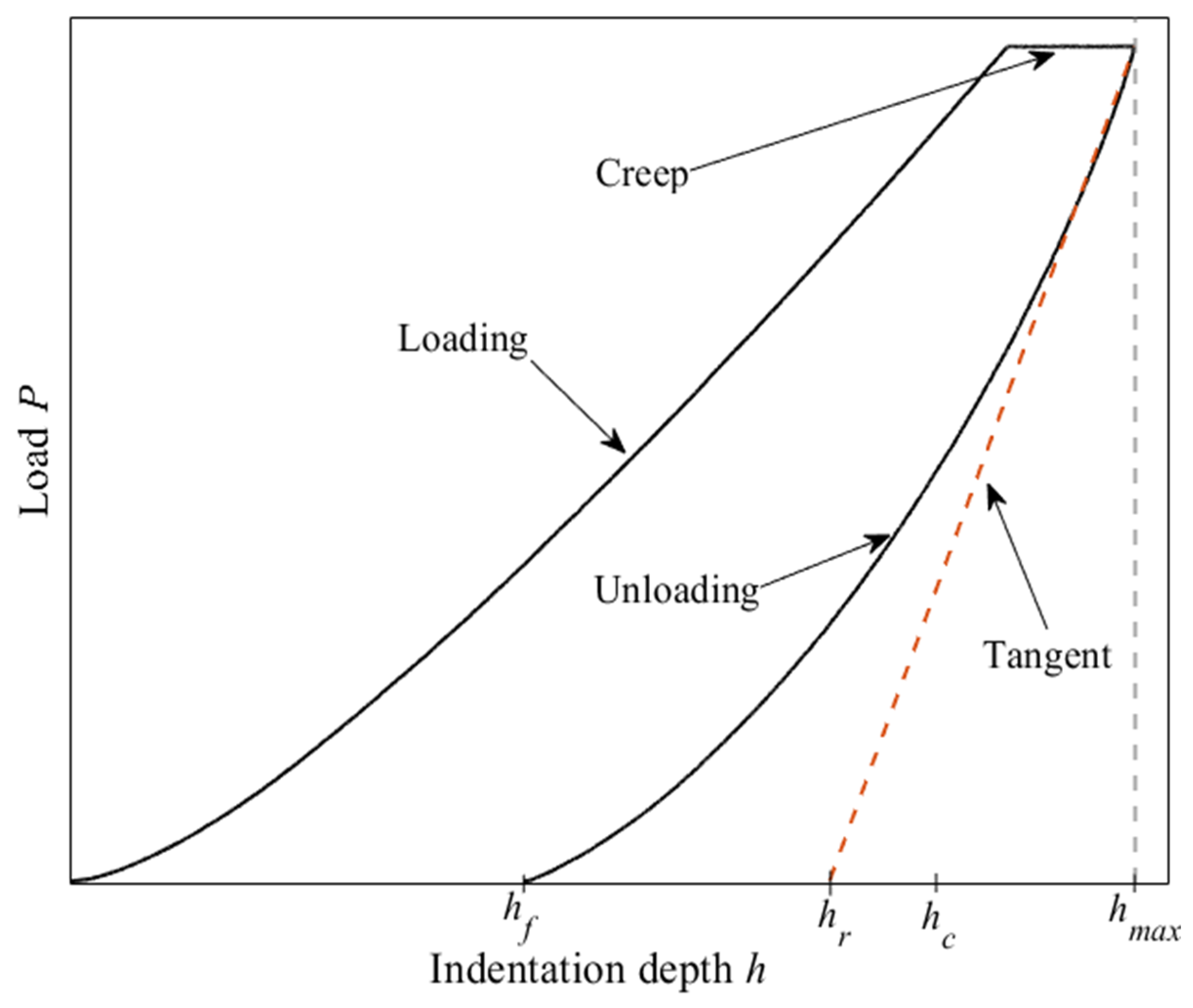
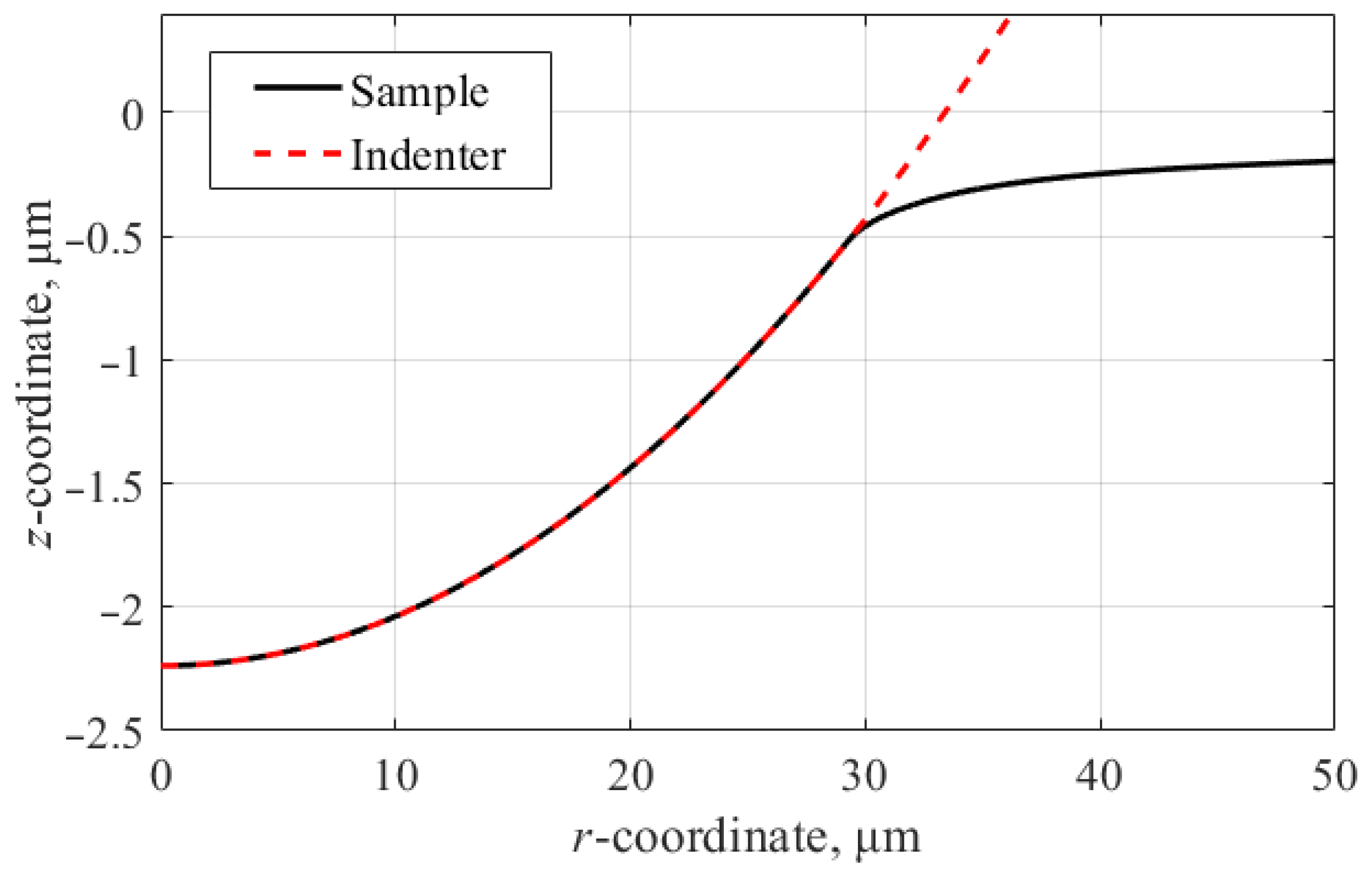
4.1. Estimation of Contact Indentation Depth

The theoretical contact depth hc was estimated using the Oliver–Pharr method, taking into account the tangent to the unloading curve (Figure 2) and Equation (1). Since the unloading angle in the experiment and the model was different, this approach determines the contact depth hc to be 1780 nm and 1758 nm for the experiment and the model, respectively. The deviation for hardness can be explained by the indenter shape function difference from the ideal spherical function, which is why calibration was performed before the tests.
In case of using the finite element method, it is possible to determine the contact depth directly using the calculated contact geometry. The cross-sectional profile of the indentation zone for obtaining the value of the projection radius r is shown in Figure 5. In this case, the contact radius of the section r = 29.26 μm, which, when calculating the contact area Ap using Equation (8), determines the value Ap = 2689 μm2 and the contact depth hc = 1718 nm. If we use these values to calculate the hardness HIT and the modulus of elasticity EIT using Expressions (1) and (2), the values will be 18.49 MPa and 1091 MPa, respectively, which is very close to the methodical principle of calculation through the tangent using the Oliver–Pharr method. This indicates the adequacy of the finite element model used in relation to the method of determining the mechanical properties using indentation diagrams (during simulation, the obtained diagram, according to the Oliver–Pharr method, gives the modulus of elasticity EIT close to the referenced one).

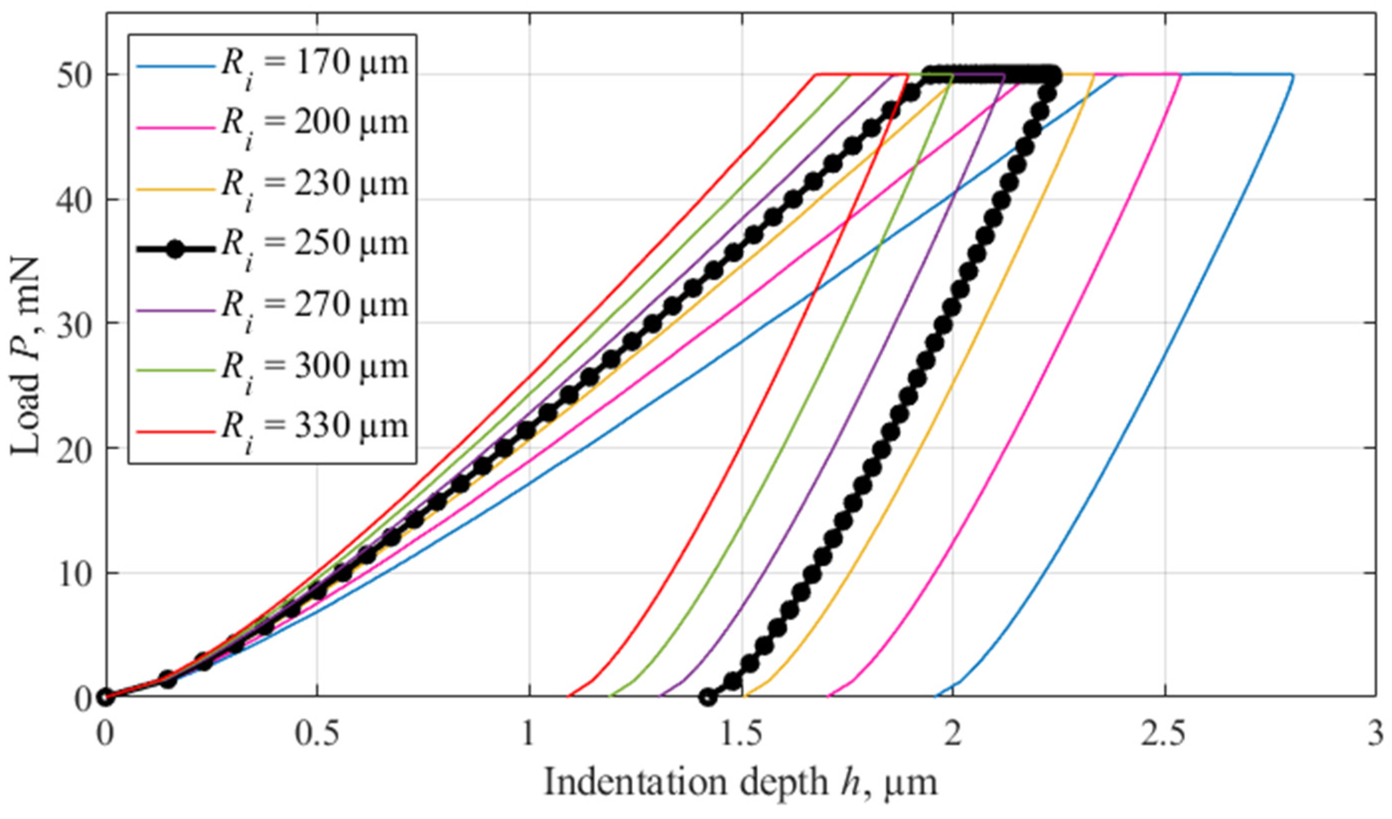
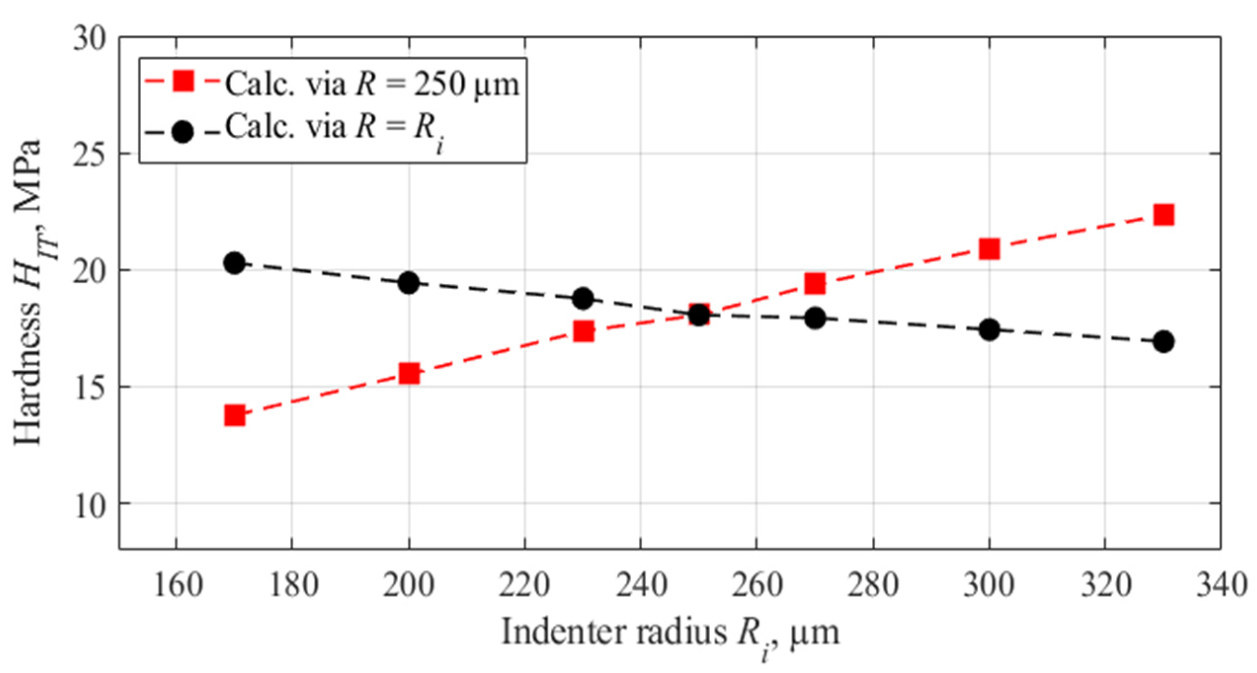
4.2. Indenter Radius Influence

Since it is generally impossible to determine the exact function of the indenter shape to assess the influence of the indenter radius on the results of calculating the mechanical properties using the Oliver–Pharr method, additional modeling of the indentation process was carried out. The indenter radius R influences the calculation of the contact area Ap according to Formula (8). The contact radius r depends on the value of the contact depth, determined according to the indentation diagram and the radius of the indenter itself. The indentation process was simulated for different indenter radii Ri = 170...330 μm, and diagrams with different contact depths were obtained. Next, the mechanical properties were calculated using these diagrams. The calculation was performed in two ways. The first was that when calculating the contact area, the radius was taken to be 250 µm, but in this case, the indentation diagrams were obtained with a different radius. Thus, the error of the indenter shape function was simulated, which allows us to estimate the error in calculating the mechanical properties. The second method of calculation was based on the fact that the radius accepted in the formulas for calculating the contact area for calculation using the Oliver–Pharr method corresponded to the radius specified during simulation. In this case, the discrepancy between the initial and calculated data was estimated. The simulation results in the form of indentation diagrams are presented in Figure 6.
The results of the calculation of mechanical properties are presented in Figure 7 and Figure 8.
Figure 7 and Figure 8 graphically represent quantitative estimates of the influence of the indenter radius error on the results of the elastic modulus and hardness determination. When using a radius in the calculations that corresponded to the radius specified in the simulation (R = Ri), it can be concluded that changes in the model parameters have an insignificant (within 5%) effect on the result of calculating the elastic modulus, while it significantly (up to 20%) affects the result of calculating the hardness values. The results showed that with an incorrect determination of the indenter shape function (R = 250 μm), a significant error in the calculated mechanical properties is observed.

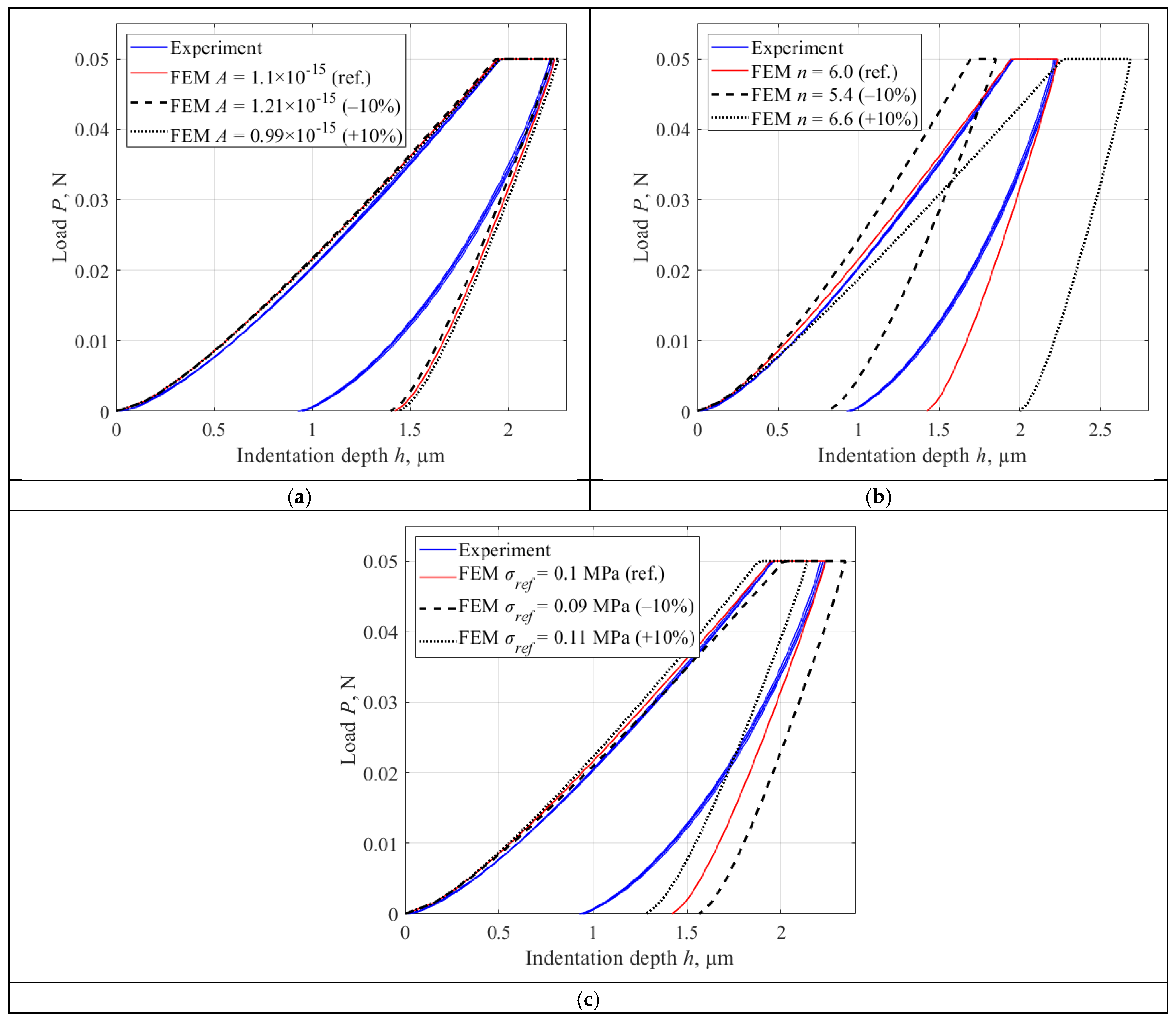
4.3. Norton Creep Material Model Parameters Influence

When optimizing the parameters of the creep function of the model, the influence of its main parameters (A, n, σref) on the indentation diagram and the properties calculated from them was determined. So, with two constant reference values (const), one of the parameters of the hardening function (var) was varied within ±10% (reference values: A = 1.1 × 10⁻¹⁵, n = 6, σref = 0.1 MPa). Indentation diagrams obtained by changing the main parameters of the creep function are presented in Figure 9. Table 5 and Table 6 presents the values of the calculated mechanical properties for each presented deviation. The parameter n has the greatest influence on the simulation results, both for the diagram and for the obtained properties.

5. Conclusions

A technique combining experimental testing and simulation was developed to determine the viscoplastic response of an HDPE material for instrumented indentation. Based on the results of the work, a number of conclusions can be drawn:
(1)
The obtained by II test values of hardness and elastic modulus, equal to 14 MPa and 1083 MPa, are consistent with reference data, the results of other studies and the results of measurements carried out using classical methods, which allows us to conclude that the II method is applicable as an alternative to tensile testing.
(2)
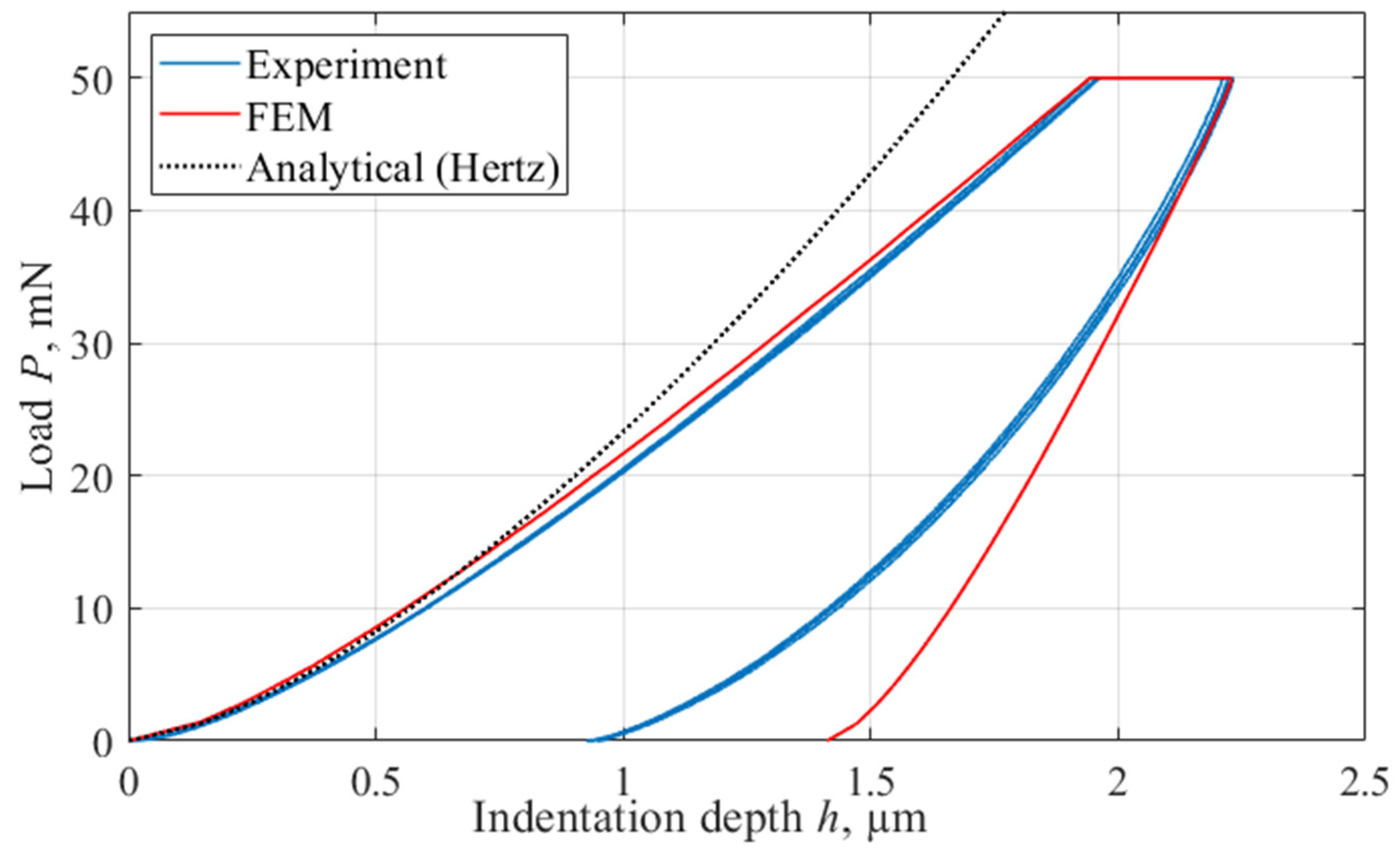
The simulation of the indentation process by FEM carried out in the work using the Norton model and determining the parameters of the material deformation function taking into account creep (A = 1.1 × 10⁻¹⁵, n = 6, σref = 0.1 MPa), allows to describe the process of contact interaction and successfully demonstrates convergence with experimental data (Figure 4 and Table 4). We can conclude that it is possible to use FEM in studying the mechanical properties of HDPE and describing the behavior of the material under load.
(3)
The paper presents the calculation of the contact depth and mechanical properties of the material based on the P(h) diagram using the Oliver–Pharr method. The error in determining the contact depth was 2.3%, which leads to an error in calculating the Young’s modulus of 1.3%. Thus, the applicability of the Oliver–Pharr method for the problem of measuring the mechanical properties of polymers using the II method is confirmed, and the adequacy of the proposed FEM in the context of the methodology for determining mechanical properties based on indentation is demonstrated.
(4)
The work studies the influence of the radius of a spherical indenter on the results of determining the mechanical properties of HDPE using the II method when the radius is varied from 170 to 330 μm. The result of determining the elastic modulus depends slightly (within 5%) on the indenter radius used in the experiment. At the same time, the obtained hardness values demonstrate a significant dependence (up to 20%), which indicates the need for strict standardization of experimental conditions to ensure reproducibility and comparability of the results.
Thus, the possibility of using computer simulation to study instrumented indentation processes has been demonstrated in order to assess the mechanical properties of high-density polyethylene, which will improve the understanding of the behavior of this material under load. Future work will be devoted to the usage of the tested model and the obtained parameters to solve problems of instrumented indentation in a dynamic setting.

Author Contributions

Methodology, editing, A.A.V.; conceptualization, editing, K.V.G.; simulation, development and description of models, preparation of draft, writing, K.I.D.; conducting experimental studies, processing experimental results, writing, E.K.S.; preparation of draft, writing, editing, A.V.M. All authors have read and agreed to the published version of the manuscript.

Funding

This research received no external funding.

Institutional Review Board Statement

Not applicable.

Informed Consent Statement

Not applicable.

Data Availability Statement

The raw data supporting the conclusion of this article will be made available by the author on request.

Conflicts of Interest

The authors declare no conflicts of interest.

Abbreviations

The following abbreviations are used in this manuscript:
HDPEhigh-density polyethylene
FEMFinite element method
IIInstrumented indentation

References

  1. Shen, J.; Liang, J.; Lin, X.; Lin, H.; Yu, J.; Yang, Z. Recent Progress in Polymer-Based Building Materials. Int. J. Polym. Sci. 2020, 2020, 8838160. [Google Scholar] [CrossRef]
  2. Chen, S.; Lai, H.S.; Lin, R.; Duan, X.H. Study on the creep properties of butt fusion–welded joints of HDPE pipes using the nanoindentation test. Weld. World 2022, 66, 135–144. [Google Scholar] [CrossRef]
  3. Arora, G.; Pathak, H. Nanoindentation characterization of polymer nanocomposites for elastic and viscoelastic properties: Experimental and mathematical approach. Compos. Part. C Open Access 2021, 4, 100103. [Google Scholar] [CrossRef]
  4. Torskaya, E.V.; Yakovenko, A.A.; Shkaley, I.V.; Svistkov, A.L. An indentation study of the temperature-dependent properties of modified polyurethanes. Fiz. Mezomekhanika 2023, 3, 505–513. [Google Scholar] [CrossRef]
  5. Hardiman, M.; Vaughan, T.J.; McCarthy, C.T. A review of key developments and pertinent issues in nanoindentation testing of fibre reinforced plastic microstructures. Compos. Struct. 2017, 180, 782–798. [Google Scholar] [CrossRef]
  6. Christöfl, P.; Czibula, C.; Seidlhofer, T.; Berer, M.; Macher, A.; Helfer, E.; Schrank, T.; Oreski, G.; Teichert, C.; Pinter, G. Morphological characterization of semi-crystalline POM using nanoindentation. Int. J. Polym. Anal. Charact. 2021, 26, 692–706. [Google Scholar] [CrossRef]
  7. Schieppati, J.; Gehling, T.; Azevedo, M.; Kerschbaumer, R.C.; Christöfl, P.; Oreski, G.; Fasching, M.A.; Schwarz, T.; Pinter, G. Investigation into the state of cure of elastomers through nanoindentation. Polym. Test. 2024, 133, 108417. [Google Scholar] [CrossRef]
  8. Christöfl, P.; Ottersböck, B.; Czibula, C.; Macher, A.; Teichert, C.; Pinter, G.; Oreski, G. Nanoindentation for Fast Investigation of PET Film Degradation. JOM 2022, 74, 2287–2294. [Google Scholar] [CrossRef]
  9. Christöfl, P.; Czibula, C.; Berer, M.; Oreski, G.; Teichert, C.; Pinter, G. Comprehensive investigation of the viscoelastic properties of PMMA by nanoindentation. Polym. Test. 2021, 93, 106978. [Google Scholar] [CrossRef]
  10. Zhao, Y.; Li, H.; Zhang, Z.; Celli, J.; Percec, S.; Ren, F. Nanoindentation study of time-dependent mechanical properties of ultra-high-molecular-weight polyethylene (UHMWPE) at different temperatures. Polym. Test. 2020, 91, 106787. [Google Scholar] [CrossRef]
  11. Poulose, A.M.; Elnour, A.Y.; Samad, U.A.; Alam, M.A.; George, J.; Sarmah, A.K.; Al-Zahrani, S.M. Nano-indentation as a tool for evaluating the rheological threshold in polymer composites. Polym. Test. 2019, 80, 106150. [Google Scholar] [CrossRef]
  12. Spinelli, G.; Guarini, R.; Ivanov, E.; Calabrese, E.; Raimondo, M.; Longo, R.; Guadagno, L.; Vertuccio, L. Nanoindentation Response of Structural Self-Healing Epoxy Resin: A Hybrid Experimental–Simulation Approach. Polymers 2024, 16, 1849. [Google Scholar] [CrossRef] [PubMed]
  13. Briscoe, B.J.; Fiori, L.; Pelillo, E. Nanoindentation of polymeric surfaces. J. Phys. D Appl. Phys. 1998, 31, 2395–2405. [Google Scholar] [CrossRef]
  14. Wang, Y.; Shang, L.; Zhang, P.; Yan, X.; Zhang, K.; Dou, S.; Zhao, J.; Li, Y. Measurement of viscoelastic properties for polymers by nanoindentation. Polym. Test. 2020, 83, 106353. [Google Scholar] [CrossRef]
  15. Zha, S.; Lan, H.-Q.; Lin, N.; Liu, Y.; Meng, T. Investigating the time- and space-dependent mechanical, physical and chemical properties of aged polyethylene gas pipes using nanoindentation tests. J. Mater. Res. Technol. 2023, 24, 3383–3398. [Google Scholar] [CrossRef]
  16. Byrne, N.; Ghanei, S.; Espinosa, S.M.; Neave, M. Influence of Hydrogen on Vintage Polyethylene Pipes: Slow Crack Growth Performance and Material Properties. Int. J. Energy Res. 2023, 2023, 1–8. [Google Scholar] [CrossRef]
  17. Wang, Z.; Wang, B.; Xiang, A.; Jiao, D.; Yu, F.; Zhang, Q.; Zhao, X. Comparative study on the performance of butt fusion-welding processes for nuclear safety class large-diameter thick-walled PE pipes. Nuclear Engineering and Technology. Korean Nucl. Soc. 2024, 56, 4184–4194. [Google Scholar] [CrossRef]
  18. Shaheer, M.; Troughton, M.; Khamsehnezhad, A.; Song, J. A study of the micro-mechanical properties of butt fusion-welded joints in HDPE pipes using the nanoindentation technique. Weld. World 2017, 61, 819–831. [Google Scholar] [CrossRef]
  19. Rajaoalison, H.; Zlotkowski, A.; Rambolamanana, G. Mechanical Properties of Sandstone using non-Destructive Method. J. Min. Inst. 2020, 241, 113–117. [Google Scholar] [CrossRef]
  20. Mogilner, L.Y.; Syasko, V.A.; Shikhov, A.I. Modeling Defects in Ultrasonic Nondestructive Testing: State-of-the-Art and Prospects. Russ. J. Nondestruct. Test. 2024, 60, 481–500. [Google Scholar] [CrossRef]
  21. Schipachev, A.M.; Dmitrieva, A.S. Application of the resonant energy separation effect at natural gas reduction points in order to improve the energy efficiency of the gas distribution system. J. Min. Inst. 2021, 248, 253–259. [Google Scholar] [CrossRef]
  22. Pryakhin, E.I.; Azarov, V.A. Increasing the adhesion of fluoroplastic coatings to steel surfaces of pipes with a view to their use in gas transmission systems. Chernye Met. 2024, 3, 69–75. [Google Scholar] [CrossRef]
  23. Zha, S.; Lan, H.-Q.; Lin, N.; Meng, T. Degradation and characterization methods for polyethylene gas pipes after natural and accelerated aging. Polym. Degrad. Stab. 2023, 208, 110247. [Google Scholar] [CrossRef]
  24. Majid, F.; Rhanim, R.; Lahlou, M.; Rhanim, H.; Ezzahi, M.; Elghorba, M. Maintainability and reliability of high density polyethylene pipes through experimental and theoretical models. Procedia Struct. Integr. 2020, 25, 430–437. [Google Scholar] [CrossRef]
  25. Gogolinskiy, K.V.; Vinogradova, A.A.; Kopylova, T.N.; Povarov, V.G.; Vasilev, E.A.; Shchiptsova, E.K.; Rybkin, D.E.; Kolobov, D.S. Study of physicochemical properties of polyethylene gas pipelines material with a prolonged service life. Int. J. Press. Vessel. Pip. 2022, 200, 104825. [Google Scholar] [CrossRef]
  26. Palaev, A.G.; Fuming, Z. A Leak Detection Method for Underground Polyethylene Gas Pipelines Using Simulation Software Ansys Fluent. Int. J. Eng. 2024, 37, 1615–1621. [Google Scholar] [CrossRef]
  27. ISO 6259-1:2015; Thermoplastics Pipes—Determination of Tensile Properties—Part 1: General Test Method. ISO: Geneva, Switzerland, 2015.
  28. Song, P.; Trivedi, A.; Siviour, C.R. Tensile testing of polymers: Integration of digital image correlation, infrared thermography and finite element modelling. J. Mech. Phys. Solids. 2023, 171, 105161. [Google Scholar] [CrossRef]
  29. Gogolinskiy, K.; Gromyka, D.; Kremcheev, E. A Modelling of Cyclic Thermal and Impact Loads on Excavator Bucket. Int. Rev. Mech. Eng. (IREME) 2021, 15, 189–196. [Google Scholar] [CrossRef]
  30. Afanaseva, O.V.; Putilo, S.Y.; Chirtsov, V.V.; Demidov, A.A. Simulation of the work of structural units of industrial enterprises using the theory of queuing systems. Acad. J. Manuf. Eng. 2024, 22, 115–126. [Google Scholar]
  31. Sleptsov, A.; Medvedeva, L.; Marinina, O.; Savenok, O. Feasibility Study on the Applicability of Intelligent Well Completion. Processes 2024, 12, 1565. [Google Scholar] [CrossRef]
  32. Gromyka, D.S.; Utenkova, T.G.; Korotkova, O.Y. Estimation methods of wear mechanisms in cutting heads of mining machines: Review. Min. Informational Anal. Bull. 2021, 2, 75–86. [Google Scholar] [CrossRef]
  33. Gorbunov, A.E.; Solomenchuk, P.V.; Umanskii, A.S. Modeling a Two-Element Tangential Eddy Current Probe with Active Shielding for Soldered Joint Testing. Russ. J. Nondestruct. Test. 2024, 60, 912–920. [Google Scholar] [CrossRef]
  34. Louche, H.; Piette-Coudol, F.; Arrieux, R.; Issartel, J. An experimental and modeling study of the thermomechanical behavior of an ABS polymer structural component during an impact test. Int. J. Impact Eng. 2009, 36, 847–861. [Google Scholar] [CrossRef]
  35. Loseva, E.; Lozovsky, I.; Zhostkov, R. Refining Low Strain Pile Integrity Testing for Minor Flaw Detection with Complex Wavelet Transform. Civ. Eng. J. 2024, 10, 3194–3207. [Google Scholar] [CrossRef]
  36. Peng, C.; Zeng, F. A molecular simulation study to the deformation Behaviors and the size effect of polyethylene during nanoindentation. Comput. Mater. Sci. 2017, 137, 225–232. [Google Scholar] [CrossRef]
  37. Hu, E.; Sun, Y.; Zeng, F.; Qu, J. Nanoindentation simulation of PE/POSS under different shapes of indenters. Acta Mech. Solida Sin. 2011, 24, 365–372. [Google Scholar] [CrossRef]
  38. Li, H.; Chen, J.; Chen, Q.; Liu, M. Determining the constitutive behavior of nonlinear visco-elastic-plastic PMMA thin films using nanoindentation and finite element simulation. Mater. Des. 2021, 197, 109239. [Google Scholar] [CrossRef]
  39. Balobanov, V.; Verho, T.; Heino, V.; Ronkainen, H.; Pelto, J. Micromechanical performance of high-density polyethylene: Experimental and modeling approaches for HDPE and its alumina-nanocomposites. Polym. Test. 2021, 93, 106936. [Google Scholar] [CrossRef]
  40. Won, J.; Kim, S.; Kwon, O.M.; Kim, Y.-C.; Kwon, D. Evaluation of tensile yield strength of high-density polyethylene in flat-ended cylindrical indentation: An analytic approach based on the expanding cavity model. J. Mater. Res. 2020, 35, 206–214. [Google Scholar] [CrossRef]
  41. Brazil, O.; de Silva, J.P.; Pethica, J.B.; Cross, G.L.W. Extrinsic plastic hardening of polymer thin films in flat punch indentation. Philos. Mag. 2021, 101, 1327–1342. [Google Scholar] [CrossRef]
  42. Gnatowski, A.; Kijo-Kleczkowska, A.; Chyra, M.; Kwiatkowski, D. Numerical-experimental analysis of polyethylene pipe deformation at different load values. Materials 2021, 14, 160. [Google Scholar] [CrossRef] [PubMed]
  43. Rueda, F.; Torres, J.; Machado, M.; Frontini, P.; Otegui, J. External pressure induced buckling collapse of high density polyethylene (HDPE) liners: FEM modeling and predictions. Thin-Walled Struct. 2015, 96, 56–63. [Google Scholar] [CrossRef]
  44. Lamri, A.; Shirinbayan, M.; Pereira, M.; Truffault, L.; Fitoussi, J.; Lamouri, S.; Bakir, F.; Tcharkhtchi, A. Effects of strain rate and temperature on the mechanical behavior of high-density polyethylene. J. Appl. Polym. Sci. 2020, 137, 48778. [Google Scholar] [CrossRef]
  45. Amjadi, M.; Fatemi, A. Tensile behavior of high-density polyethylene including the effects of processing technique, thickness, temperature, and strain rate. Polymers 2020, 12, 1857. [Google Scholar] [CrossRef] [PubMed]
  46. Li, Y.; Luo, W.; Li, M.; Yang, B.; Liu, X. Strain Rate-Dependent Hyperbolic Constitutive Model for Tensile Behavior of PE100 Pipe Material. Polymers 2022, 14, 1357. [Google Scholar] [CrossRef] [PubMed]
  47. May, D.L.; Gordon, A.P.; Segletes, D.S. The Application of the Norton-Bailey Law for Creep Prediction Through Power Law Regression. Structures and Dynamics. In Proceedings of the ASME Turbo Expo 2013: Turbine Technical Conference and Exposition, San Antonio, TX, USA, 3–7 June 2013; American Society of Mechanical Engineers: New York, NY, USA, 2013; Volume 7A. [Google Scholar] [CrossRef]
  48. Brathe, L.; Josefson, L. Estimation of Norton-Bailey parameters from creep rupture data. Met. Sci. 1979, 13, 660–664. [Google Scholar] [CrossRef]
  49. O’Masta, M.R.; Crayton, D.H.; Deshpande, V.S.; Wadley, H.N.G. Mechanisms of penetration in polyethylene reinforced cross-ply laminates. Int. J. Impact Eng. 2015, 86, 249–264. [Google Scholar] [CrossRef]
  50. Torres, J.P.; Frontini, P.; Machado, M.; Major, Z. Deformation and failure of semicrystalline polymers under dynamic tensile and biaxial impact loading. Int. J. Impact Eng. 2016, 98, 52–61. [Google Scholar] [CrossRef]
  51. Ginder, R.S.; Nix, W.D.; Pharr, G.M. A simple model for indentation creep. J. Mech. Phys. Solids 2018, 112, 552–562. [Google Scholar] [CrossRef]
  52. Dean, J.; Bradbury, A.; Aldrich-Smith, G.; Clyne, T. A procedure for extracting primary and secondary creep parameters from nanoindentation data. Mech. Mater. 2013, 65, 124–134. [Google Scholar] [CrossRef]
  53. Starkova, O.; Gagani, A.I.; Karl, C.W.; Rocha, I.B.C.M.; Burlakovs, J.; Krauklis, A.E. Modelling of environmental ageing of polymers and polymer composites—Durability prediction methods. Polymers 2022, 14, 907. [Google Scholar] [CrossRef]
  54. Drozdov, A.D.; Høj Jermiin, R.; de Claville Christiansen, J. Lifetime Predictions for High-Density Polyethylene under Creep: Experiments and Modeling. Polymers 2023, 15, 334. [Google Scholar] [CrossRef] [PubMed]
  55. COMSOL Multiphysics®; v. 6.3.; COMSOL AB: Stockholm, Sweden, 2025; Available online: www.comsol.com (accessed on 11 March 2025).
  56. ISO 14577-1:2015; Metallic Materials—Instrumented Indentation Test for Hardness and Materials Parameters Part 1: Test Method. ISO: Geneva, Switzerland, 2015.
  57. Peng, C.; Zeng, F.; Yuan, B.; Wang, Y. An MD simulation study to the indentation size effect of polystyrene and polyethylene with various indenter shapes and loading rates. Appl. Surf. Sci. 2019, 492, 579–590. [Google Scholar] [CrossRef]
  58. Mokhtari, A.; Tala Ighil, N. Identification of the elasto-viscoplastic parameters for a thermoplastic polymer by instrumented indentation. IOP Conf. Ser. Mater. Sci. Eng. 2018, 461, 012057. [Google Scholar] [CrossRef]
  59. Oliver, W.C.; Pharr, G.M. Measurement of hardness and elastic modulus by instrumented indentation: Advances in understanding and refinements to methodology. J. Mater. Res. 2004, 19, 3–20. [Google Scholar] [CrossRef]
  60. O’Connor, J.; dos Santos, B.B.; Borges, L.; da Costa, M.F.; Castello, D.A. Computational modeling of viscoplastic polymeric material response during micro-indentation tests. J. Braz. Soc. Mech. Sci. Eng. 2020, 42, 1–18. [Google Scholar] [CrossRef]
  61. Lu, X.; Xu, H.; Zhao, B. Effect of hardening exponent of power-law hardening elastic-plastic substrate on contact behaviors in coated asperity contact. Materials 2018, 11, 1965. [Google Scholar] [CrossRef] [PubMed]
  62. Clyne, T.W.; Campbell, J.E. Indentation Plastometry. In Testing of the Plastic Deformation of Metals; Cambridge University Press: Cambridge, UK, 2021; pp. 148–191. [Google Scholar] [CrossRef]
  63. Diana, L.; Safitra, A.G.; Muhammad, G. Tensile Test Simulation for Polymer Composites. Adv. Eng. Res. 2021, 208, 200–206. Available online: https://www.atlantis-press.com/proceedings/icist-20/125964989 (accessed on 11 March 2025). [CrossRef]
  64. Sedmak, S.; Golubovic, Z.; Murariu, A.; Sedmak, A. Numerical simulation of tensile testing of PE 80 polymer specimens. Therm. Sci. 2018, 22 Pt B, 641–649. [Google Scholar] [CrossRef]
  65. Nakai, K.; Yokoyama, T. Uniaxial Compressive Response and Constitutive Modeling of Selected Polymers Over a Wide Range of Strain Rates. J. Dyn. Behav. Mater. 2015, 1, 15–27. [Google Scholar] [CrossRef]
  66. Haward, R.N. Strain hardening of high density polyethylene. J. Polym. Sci. B Polym. Phys. 2007, 45, 1090–1099. [Google Scholar] [CrossRef]
  67. Vasilyeva, M.; Nagornov, D.; Orlov, G. Research on Dynamic and Mechanical Properties of Magnetoactive Elastomers with High Permeability Magnetic Filling Agent at Complex Magneto-Temperature Exposure. Materials 2021, 14, 2376. [Google Scholar] [CrossRef]
  68. Van Der Stok, E.; Scholten, F. Strain hardening tests on PE pipe materials. In Proceedings of the Plastic Pipes XVI Conference, Barcelona, Spain, 24–26 September 2012. [Google Scholar]
  69. Yu, S.; Lu, Y.; Cai, Y. The strain-rate effect of engineering materials and its unified model. Lat. Am. J. Solids Struct. 2013, 10, 833–844. [Google Scholar] [CrossRef]
  70. Xiao, H.R.; Cai, L.X.; Han, G.Z. Semi-analytical creep model to obtain Norton’s law of materials under flat indentation and its applications. J. Mater. Res. Technol. 2023, 25, 905–911. [Google Scholar] [CrossRef]
  71. Fusek, M.; Paška, Z.; Rojíček, J.; Fojtík, F. Parameters identification of the Anand material model for 3D printed structures. Materials 2021, 14, 587. [Google Scholar] [CrossRef] [PubMed]
  72. Sattar, M.; Othman, A.; Kamaruddin, S.; Akhtar, M.; Khan, R. Limitations on the computational analysis of creep failure models: A review. Eng. Fail. Anal. 2022, 134, 105968. [Google Scholar] [CrossRef]
  73. Ovsik, M.; Maňas, D.; Maňas, M.; Staněk, M.; Kyas, K.; Bednařík, M.; Mizera, A. Microhardness of HDPE influenced by Beta Irradiation. Int. J. Math. Comput. Simul. 2012, 6, 566–574. [Google Scholar]
  74. Manaia, J.P.; Pires, F.A.; de Jesus, A.M.; Wu, S. Mechanical response of three semi crystalline polymers under different stress states: Experimental investigation and modelling. Polym. Test. 2020, 81, 106156. [Google Scholar] [CrossRef]
  75. Pelto, J.; Heino, V.; Karttunen, M.; Rytöluoto, I.; Ronkainen, H. Tribological performance of high density polyethylene (HDPE) composites with low nanofiller loading. Wear 2020, 460–461, 203451. [Google Scholar] [CrossRef]
  76. Manas, D.; Dobransky, J.; Chvatalova, L. Ultra nano-hardness of surface layer of irradiated high–density polyethylene (HDPE). MATEC Web Conf. 2017, 125, 02044. [Google Scholar] [CrossRef]
  77. Bai, S.L. Indentation properties of the filler and matrix in polymer composites. J. Mater. Sci. Lett. 2002, 21, 85–88. [Google Scholar] [CrossRef]
  78. Colak, O.U.; Dusunceli, N. Modeling viscoelastic and viscoplastic behavior of high density polyethylene (HDPE). J. Eng. Mater. Technol. Am. Soc. Mech. Eng. (ASME) 2006, 128, 572–578. [Google Scholar] [CrossRef]
Figure 1. Sample appearance after sample preparation (a); conducting experimental studies using the II method (b).
Applmech 06 00029 g001
Figure 2. Indentation diagram with the main stages of loading (hf—residual depth of the indentation after removing the load, hc—contact depth, hr—point of intersection of the tangent to the unloading stage, hmax—maximum indentation depth).
Applmech 06 00029 g002
Figure 3. Used geometry of the model (1—indenter, 2—sample).
Applmech 06 00029 g003
Figure 4. Comparison of the simulation results with the experiment and Hertz analytical model of the elastic interaction at E = 1.0 GPa.
Applmech 06 00029 g004
Figure 5. Cross-sectional profile of the indentation zone.
Applmech 06 00029 g005
Figure 6. Comparison of simulation results with various indenter radius Ri.
Applmech 06 00029 g006
Figure 7. Comparison of elastic modulus calculation results for simulations with different indenter radius Ri.
Applmech 06 00029 g007
Figure 8. Comparison of hardness calculation results for simulations with different indenter radius Ri.
Applmech 06 00029 g008
Figure 9. Indentation diagrams ((a): A = var, (b): n = var, (c): σref = var).
Applmech 06 00029 g009
Table 1. Loading modes during II.
ParameterValue
Loading time tl and unloading time tu, s35
Hold time th, s35
Load P, mN50
Table 2. Properties of materials for simulation.
MaterialPoisson’s Ratio νElastic Modulus E, GPaDensity ρ, kg/m3
Silicon Carbide SiC0.174123210
HDPE PE1000.441.00950
Table 3. Experimental results for II test simulation.
ValueHardness HIT, MPaElastic Modulus EIT, MPaIndentation Depth hmax, nmRecovery Coefficient rc, %
Mean14.091083222276.7
SD0.04490.5
Table 4. Comparison of the II experiment and the model.
MethodHardness HIT, MPaElastic Modulus EIT, MPaIndentation Depth hmax, nmRecovery Coefficient rc, %
FEM18.061078222963.6
Experiment14.09 ± 0.041083 ± 42222 ± 976.7 ± 0.5
Table 5. Comparison of simulation results via hardness for different parameters, MPa.
VariationCondition
A = var
n, σref = const
n = var
A, σref = const
σref = var
A, n = const
Reference Model
var +10%17.8913.8919.4218.06
var −10%18.2925.3016.89
Table 6. Comparison of simulation results via elastic modulus for different parameters, MPa.
VariationCondition
A = var
n, σref = const
n = var
A, σref = const
σref = var
A, n = const
Reference Model
var +10%1074114510621078
var −10%107510361096
Disclaimer/Publisher’s Note: The statements, opinions and data contained in all publications are solely those of the individual author(s) and contributor(s) and not of MDPI and/or the editor(s). MDPI and/or the editor(s) disclaim responsibility for any injury to people or property resulting from any ideas, methods, instructions or products referred to in the content.

