Article

Effect of TiO2 Photoanodes Morphology and Dye Structure on Dye-Regeneration Kinetics Investigated by Scanning Electrochemical Microscopy

1
Chemistry Department, School of Mathematics and Science, Carl von Ossietzky University of Oldenburg, D-26111 Oldenburg, Germany
2
Laboratory of Photomolecular Science, SB ISIC, École polytechnique fédérale de Lausanne, CH G1 523 Bâtiment CH, CH-1015 Lausanne, Switzerland
*
Author to whom correspondence should be addressed.
Electrochem 2020, 1(3), 329-343; https://doi.org/10.3390/electrochem1030021
Submission received: 3 July 2020 / Revised: 20 August 2020 / Accepted: 26 August 2020 / Published: 1 September 2020

Abstract

:
The dye regeneration in dye-sensitized solar cells (DSSCs) is improved by optimizing the charge separation at the level of the sensitized semiconductor treatment of the mesoporous electrode by TiCl4 that passivates the surface for back electron transfer reactions. The dye-regeneration kinetics is analyzed for DN216- and D358-sensitized porous TiO2 electrodes with and without a TiCl4 treatment by means of scanning electrochemical microscopy (SECM). Different mass transport limitation of the [Co(bpy)3]3+ mediator through the porous electrode is found for the comparison of the structurally similar dyes but cannot be detected for the thin layer introduced by the TiCl4 treatment. Phototransient measurements are conducted directly in the SECM cell without any intermediated sample manipulation. The results from those measurements corroborate the findings from steady state SECM measurements.

Graphical Abstract

1. Introduction

The dye-sensitized solar cells (DSSCs) were originally developed by O’Regan and Grätzel in 1991 [1]. TiO2-based devices were reported to have photoconversion efficiencies of up to 12.7% [2], a value halfway of the theoretical maximum estimated to be around 30% [3,4]. The mechanism of photon-conversion into electrons takes place at the sensitized semiconductor [5]. The coupled processes are depicted and numbered in Figure 1. A dye molecule (D) absorbs solar light (1) and injects an electron in the conduction band (CB) of the TiO2 film (2), on which it is adsorbed [5,6]. Inside the semiconductor, the electron is transported by a diffusion process (3) to the back contact, during which the conduction band electrons eCB temporarily reside in traps near to the CB edge, from which they can be thermally activated [7,8]. The photo-oxidized dye is thereafter regenerated by a mediator (4) in the electrolyte [9]. Due to space requirements, the redox mediator [Co(bpy)3]2+/3+, in its reduced and oxidized form is represented either by R/O or , /- in Figure 1. In an illuminated photoanode, the photo-oxidized dye (D+) and the eCB can be considered as an electron-hole pair that can either recombine (5) or separate [10]. In general, the high dielectric permittivity of TiO2 supports the charge separation [11,12]. During the transport to the back contact (3), eCB can be lost by “back electron transfer reaction” which are the heterogeneous electron transfer (ET) reactions of eCB to the oxidized mediator (6) in the electrolyte or, less frequently, to D+ (5) [12]. These processes are also called “recombination” because they restore the electronic state before the photo-excitation. The unwanted loss processes 5 and 6 limit the effective life time of eCB [13,14]. If electrons are retained in trap states located near the TiO2|solution interface, the probabilities for an ET to the oxidized form of the mediator (6′) or to D+ (5′) are dramatically increased and may limit the overall device performance [6]. A common approach to increase the device performance consists in diminishing the trap concentration near the inner surface of the nanoporous photoanodes.
In this work, the dye-regeneration kinetics of TiO2-based photoanodes were analyzed for two different nanoporous TiO2 electrodes and two all-organic dyes as sensitizers. The aim was to quantify the influence of reduced back electron transfer reactions from near-surface trap states on the overall dye-regeneration efficiency, which is expected to enhance the overall photovoltaic performances. Mesoporous TiO2 films are commonly treated by an aqueous TiCl4 solution in order to improve the efficiency of dye-sensitized solar cells [15]. This treatment covers the surface of mesoporous TiO2 film by rutile TiO2 and increases the light scattering property of the film [16]. Several studies have been reported to explain the effects of the post-TiCl4 treatment. The particle size of TiO2 increased from 13 nm for the primary TiO2 nanoparticles to ca. 15 nm by the covering layer [17]. Impurities at the surface of the initial mesoporous TiO2 film are cleaned during the process and a pure TiO2 surface is obtained [15]. Although the surface area of the mesoporous TiO2 film (as measured by gas adsorption) decreased by this treatment, the dye loading increases since the area accessible to the dye molecules and the cleanness of the particles are improved [18,19]. A shift of the CB to a lower potential was also observed and it leads to an enhanced electron injection from the excited dye [17,20]. At last, a stronger bond was observed between the adsorbed dye and TiO2 from infrared absorption spectroscopy [21]. Such a strengthen bonding and a better surface coverage of the TiO2 particles by dye molecules inhibit the ET of eCB oxidized mediator in the electrolyte solution. This effect is measured as an enhanced open-circuit photovoltage [22]. Due to those positive effects, the post-TiCl4 treatment is commonly applied for the fabrication of dye-sensitized solar cells [22,23] and its effect has been summarized as passivation against losses of eCB.
Variation of the thickness of photoanodes can increase the light absorption. However, this effect may be counteracted and even overcompensated by increased possibilities for loss processes at a larger inner surface [24] and mediator mass transport limitation inside the porous network [25,26] as was found from the analysis of films with thicknesses below 6 µm [24,27,28]. There are indications that, on the one hand, thicker photoanodes produce high open-circuit photovoltages resulting in enhanced photoconversion efficiency [28,29] and on the other hand exhibit a higher area for back electron transfer reactions [30]. It has been reported that the use of thin films leads to a more effective dye-regeneration kinetics favored by the limited back electron transfer reaction and faster mediator diffusion through the porous film [29].
Despite extensive work to improve photovoltaic characteristics of the TiO2 photoanode, little information has been obtained about the quantitative effect of post-TiCl4 treatment and sensitization processes on the dye-regeneration kinetics (process (4) in Figure 1). In this regard, scanning electrochemical microscopy (SECM) provides an evaluation of the dye regeneration rate constant (kox) for process 4 in Figure 1, that measures the ability of the mediator to reduce the photo-oxidized dye adsorbed on the photoanode [29,31,32]. In this work, SECM analysis is applied to passivated TiO2 photoanodes sensitized with the all-organic dye molecules D358 or DN216 (Figure 2) [33,34]. These molecules have an aliphatic chain terminated by a carboxylic group that attaches it to the semiconductor surface. A long anchoring chain prevents dye-aggregation [35] and reduces ET of eCB to the oxidized form O of the mediator [36,37] by limiting the proximal approach of O, e.g., [Co(bpy)3]3+, to the semiconductor surface [2,38]. However, sterically demanding dyes can hinder the diffusion of the mediator in the pore space (internal diffusion), a trend that is expected to become more relevant for sterically demanding mediators like [Co(bpy)3]2+/3+ and photoanodes with smaller pores [39]. This would result in less effective dye-regeneration kinetics. The steady-state approach curves in the SECM feedback modes combined with a kinetic model introduced before for the evaluation of the dye regeneration in sensitized TiO2-based photoanodes by cobalt-based mediators [32] provides a rate constant kox that is again an effective constant bearing a relation to structural features that influence the internal diffusion of the mediator in the porous photoanode.
In addition, the SECM approach has been expanded by performing transient photocurrent measurements inside the SECM cell on TiO2 photoanodes with and without post-TiCl4 treatment to qualitatively investigate the influence of the structural modification as well as the effect of the dye steric hindrance on the transient profile shape. The photocurrent recorded in on-off light cycles is indeed influenced by the mediator mass transport from the inner layers of the photoanodes towards the counter electrode [40], the porosity of the electrode [41], the eventual passivation with nanostructures [22], and the thickness of the porous film [39].

2. Materials and Methods

2.1. Materials and Chemicals

Tris-(2,2′-bipyridine)cobalt(III) tri(hexafluorophosphate) [Co(bpy)3](PF6)3 (Dyenamo, Stockholm Sweden), dye 5-[3-(carboxymethyl)-5-[[4-[4-(2,2-biphenylethenyl) phenyl] -1, 2, 3, 3a, 4, 8b-hexahydrocyclopent [b]indol-7-yl] methylene]-4-oxo-2-thiazolidinylidene]-4-oxo-2-thioxo-3-thiazolidine-hexanoic acid (DN216) and dodecanoic acid (D358) (Dyenamo), the co-adsorbant lithocholic acid (>95%, Sigma-Aldrich, Steinheim, Germany), tert-butanol (≥99.5%, Sigma-Aldrich); tetrabutylammonium hexafluorophosphate (TBAPF6, Sigma-Aldrich), acetonitrile (≥99.5%, Sigma-Aldrich), gold wire (99.999%, Goodfellow, Friedberg, Germany) were used as received.

2.2. TiO2 Film Production

The TiO2 films were prepared according to the procedure detailed before [34]. Shortly, a ca. 20 nm-TiO2 paste was screen-printed on an FTO slide already covered with a compact TiO2 layer of circa 0.6 µm. The resulting porous layers had thicknesses of 3, 4, and 6 μm. Two specimens for each thickness were sensitized by D358 or DN216 without post-TiCl4 treatment and two specimens were subjected to a post-TiCl4 treatment and later sensitized by D358 or DN216. The post-TiCl4 treatment involved the exposure of the porous TiO2 film to an aqueous solution of 53 mM TiCl4 for 30 min. As a result, the internal surface of the porous TiO2 film was covered by a layer of TiO2 nanoparticles, that form a passivation layer. The thickness of the porous films was determined by profilometry (Alpha-Step 10-00020, Tencor Instruments, Milpitas, CA, USA).

2.3. Sensitization of the Photoanodes

The electrodes were sensitized in 2 mL of a solution of a 0.5 mM DN216 or D358 and 1 mM lithocholic acid in 1:1 (v:v) acetonitrile:tert-butanol for 1 h at room temperature. The amount of dye molecule loaded on a porous semiconductor film ΓD was calculated by measuring the attenuation of the absorption of the sensitized films at 455 nm according to the Lambert-Beer equation with the decadic molar extinction coefficient of 77,600 L mol−1 cm−1 for the dye DN216 and 67,000 L mol−1 cm−1 for D358 dye [33]. The complete details of samples A to E are summarized in Table S1. That includes samples of 3, 4, and 6 µm thickness with and without passivation and sensitized with either DN216 or D358.

2.4. SECM Instrumentation

The setup for scanning electrochemical microscopy has been detailed before [32,34,42] and was run by the program SECMx [43]. The setup is shown in Figure 3 and included a piezoelectric actuator and the control electronics (P780.20 and E665, Physik Instrumente, Karlsruhe, Germany) for vertical approach, a digital potentiostat (Ref600, Gamry Instruments, Warminster, PA, USA), three SPI motors (SPI Robot, Oppenheim, Germany) to coarsely move the microelectrode (ME) relative to the sample and the light beam, and a two-dimensional positioning system (Nexcact N661.21A with controller E681, Physik Instrumente) for moving the sample horizontally at a fixed relative position between the microelectrode and the light beam. The samples were illuminated on an area of 1.5 mm2 by a blue LED (455 nm) at photon flux Jhv ranging from 0 to circa 2 × 10⁻⁷ mol cm−2 s−1. The illuminated area was selected far off the edge of the photoanode. The precise location of the analyzed area did not influence the measurements because possible local variations of properties are average on the length scale of the used microelectrode. The LED was powered by an XPOT potentiostat with a photodiode (both Zahner Elektrik, Kronach, Germany) in the beam to measure and control the actual light intensity. The light intensity was calibrated with a power meter (Gigahertz-Optik, Türkenfeld, Germany). The light beam is focused with a lens on the sample (10×, Carl Zeiss, Jena, Germany). A schematic of the setup is provided in Figure 3.
An in-house designed electrochemical cell was used. It was custom-made to work in Ar atmosphere and allowed the simple localization of the illuminated area. A soft latex finger-cot was used to close the cell against the ambient atmosphere and insert the microelectrode while allowing its translation in the three-dimensions. The cell contained 1 mL redox electrolyte solution and facilitated the exchange of the redox electrolyte and the microelectrode.
The SECM working electrodes were Au microdisk electrodes with a radius rT ≈ 25 µm and RG = rglass/rT = 14. The exact radius was determined from approach curves to a glass slide and fitting the obtained curve to an analytical model [44] The specific rT value is given in the figure captions. The auxiliary electrode and the quasi-reference electrodes were Pt wires. The mediator [Co(bpy)3](PF6)3 was used in a concentration of 0.1 mM for the approach curves and 0.2 mM for the transient measurements. The redox mediator was dissolved in acetonitrile with 0.1 M TBAPF6 as supporting electrolytes. The approach curves were recorded at a translation rate of vT = 0.5 μm s−1. The transient measurements were recorded on the sample in the SECM setup short-circuited to the redox electrolyte solution. The selected area was illuminated intermittently with 10 s on–off light cycles with a photon flux in units of 10−8 mol cm−2 s−1 of 0.76, 1.51, 2.26, 3.01, 3.77, 6.02, and 7.52. This corresponds to a flux in units of 1015 photons cm−2 s−1 of 4.58, 9.09, 13.6, 18.1, 22.7, 26.3 and 45.3. During the transient measurements the microelectrode was positioned in a distance of 10 µm from the sample and reduced [Co(bpy)3]3+ under diffusion-controlled condition to [Co(bpy)3]2+.

3. Result

3.1. SECM Approach Curves

SECM approach curves were recorded in the feedback mode on TiO2 photoanodes with and without passivation to determine the dye (D) regeneration rate constant kox of D358- and DN216-sensitized TiO2 film by [Co(bpy)3]3+ mediator. The passivation layer obtained by post-TiCl4 treatment is expected to improve the charge separation by inhibiting ET to the oxidized mediator (which would diminish the ME current) and decreasing the probability of ET from eCB to D+ so that interfacial concentration of D+ available for reaction with the reduced form of the mediator is increased compared to the non-passivated electrodes with the same dye. The variation of the kox was also tested on TiO2 photoanodes of variable thickness to expand the considerations on the effect of mediator mass transport through the porous film.

3.1.1. Treatment of the Approach Curves

The photoanodes were positioned in an adapted sample-holder in the SECM setup, which enabled the illumination of a selected area of 1.5 mm2 of the electrode through the transparent back contact. The samples were short-circuited to the solution by a Pt wire. Initially, the working solution contains only the oxidized form of the mediator [Co(bpy)3]3+ which is continuously reduced under a diffusion-controlled condition at the ME. A suitable ME potential was found from a cyclic voltammogram in the working solution. The current was controlled by the hindered diffusion of the mediator to the ME. During illumination, the dye molecules were photo-excited and injected electrons in the CB of the semiconductor. The photo-oxidized dye molecules were regenerated according to Equation (1) by the redox reaction with the reduced form of the mediator.
D + + [ Co ( bpy ) 3 ] 2 + k ox D 0 + [ Co ( bpy ) 3 ] 3 +
The electrolysis current iT at the ME is increased compared to the situation in the dark due to the additional flux of [Co(bpy)3]3+ caused by reaction (1) from the TiO2 photoanode to the ME. During an approach curve, the distance d between the ME and the photoanode is steadily decreasing, thus changing the relative contributions of the hindered diffusion of [Co(bpy)3]3+ form the bulk phase and the flux generated by the dye regeneration in reaction (1). This changing contribution of hindered mediator diffusion and dye regeneration reaction at the sample is well described by continuum simulation of the reaction-diffusion problem. Such simulation results have been condensed to an analytical approximation for an irreversible first-order reaction [45], which we used in this work. Details are provided in our notation as Supporting Material SM-2. The approach curves were plotted in normalized coordinates IT vs. L, in Figure 4, where the normalized microelectrode current IT = iT/iT,∞ is the microelectrode current iT(d) at a specific distance d normalized by the microelectrode current iT,∞ in the bulk (i.e., quasi-infinite distance). The normalized distance L = d/rT was obtained from the working distance d and the microelectrode radius rT. A fit of the experimental curve to the analytical approximation yields a dimensionless pseudo-first-order rate constant κ, from which an effective heterogeneous rate constant keff [cm s−1] for the overall dye regeneration process was obtained from Equation (2)
keff = κD/rT,
where D is the diffusion coefficient of the mediator [Co(bpy)3]3+ in the bulk solution and rT is the radius of the ME. The diffusion coefficient D for the [Co(bpy)3]3+ in the bulk was calculated as 8.3 × 10⁻⁶ cm2 s−1 from the diffusion-limited steady-state current of the reaction at the ME (Figure S4). The keff values are further related to the parameters of the photoanode in Section 4.1.

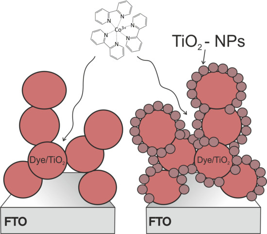
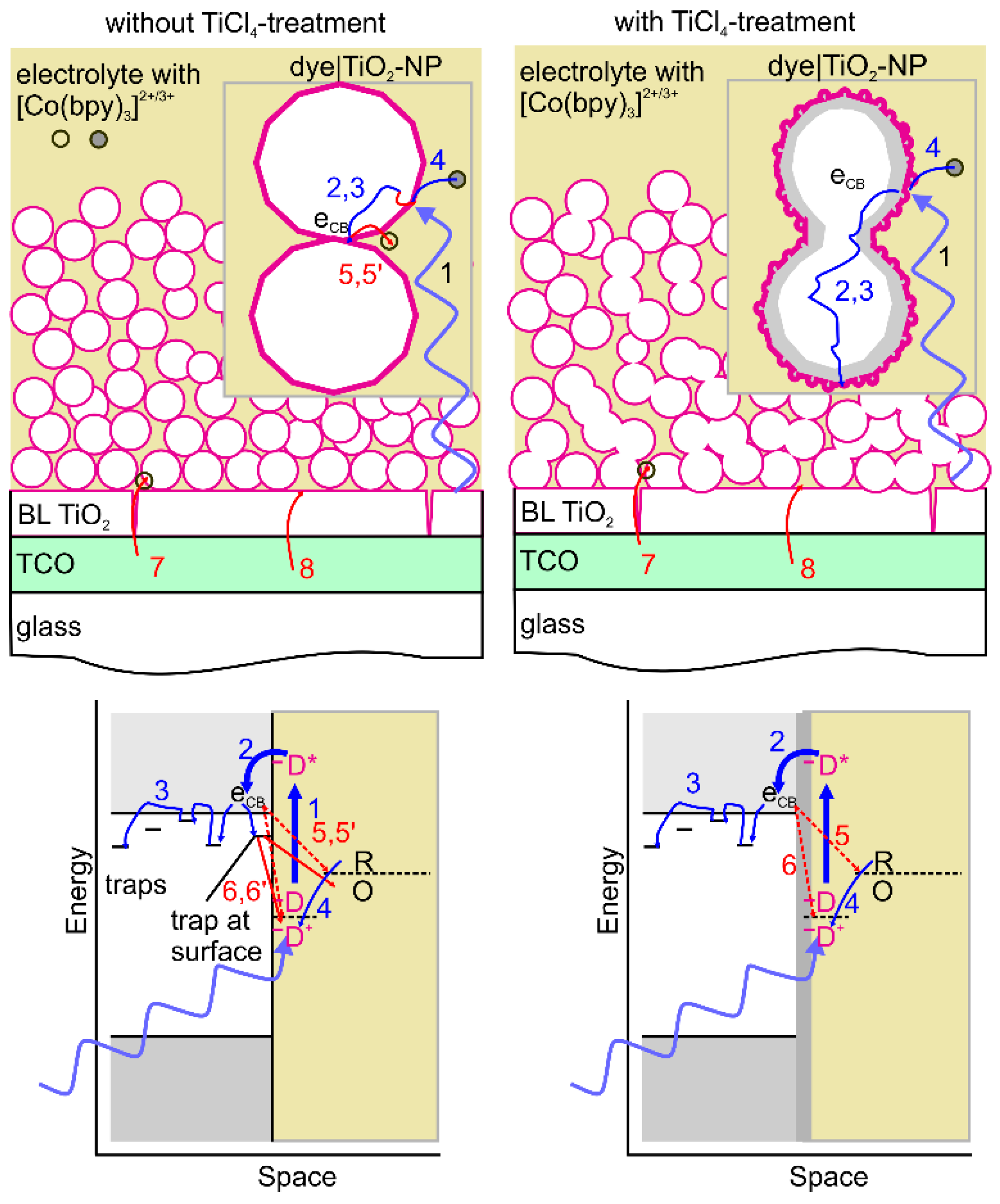
3.1.2. Effect of Post-TiCl4 Treatment

Each TiO2 photoanode was investigated under eight different light intensities Jhv by SECM approach curves in the feedback mode. Figure 4 shows the exemplary approach curves over a 4 µm thick TiO2 photoanodes C-DN216, D-DN216, C-D358, and D-D358, which will be further discussed in detail. The approach curves for samples with other thicknesses are reported in the Supporting Material (SM) in Figures S1 and S2.
The approach curves recorded in the dark overlapped with the hindered-diffusion behavior (Supporting Material (SM), SM-2 with ĸ = 0). This led to the calculation of keff values very close to zero because no photo-driven reaction took place. The very small keff results from the mediator diffusion through the porous film that hinders the diffusion slightly less than an impermeable flat sample surface. However, this contribution is very small and does not affect the applicability of the model. The negligible current enhancement also proves the effectiveness of the blocking layer between the thin conducting glass and the porous TiO2 electrode. If there were significant density of defect in the blocking layer processes 7 and 8 of Figure 1 would cause enhanced ME currents as demonstrated before [46].
The approach curves were fitted with the model for first order, finite and irreversible kinetic mediator regeneration by Cornut and Lefrou [45]. Details are provided in SM-2. The effective rate constant keff for the mediator redox reaction with the dye at the photoanode for each Jhv was calculated from κ (obtained by fitting the approach curve) and D (from Figure S3) according to Equation (2). All rate constants are collected in Tables S2 and S3. The approach curves recorded during illumination reach higher normalized currents on samples with post-TiCl4 treatment which translates to higher keff values for an identical photon flux.
Naturally, the keff values increase with the photon flux until they reached a saturation behavior at a photon flux of Jhv > 0.5×10⁻⁷ mol cm−2 s−1 (Figure 5). Similar data are reported for all TiO2 photoanodes of different thicknesses and sensitized with D358 or DN216 dye molecules in Figure S5. An enhancement of keff was detected every time that a photoanode with post-TiCl4 treatment was used (compared to the corresponding non-treated counterpart). The enhancement was particularly strong when the dye DN216 with the small anchoring chain had been used for the sensitization. The increase of keff will be related to the structure of the photoanode in Section 4.1.

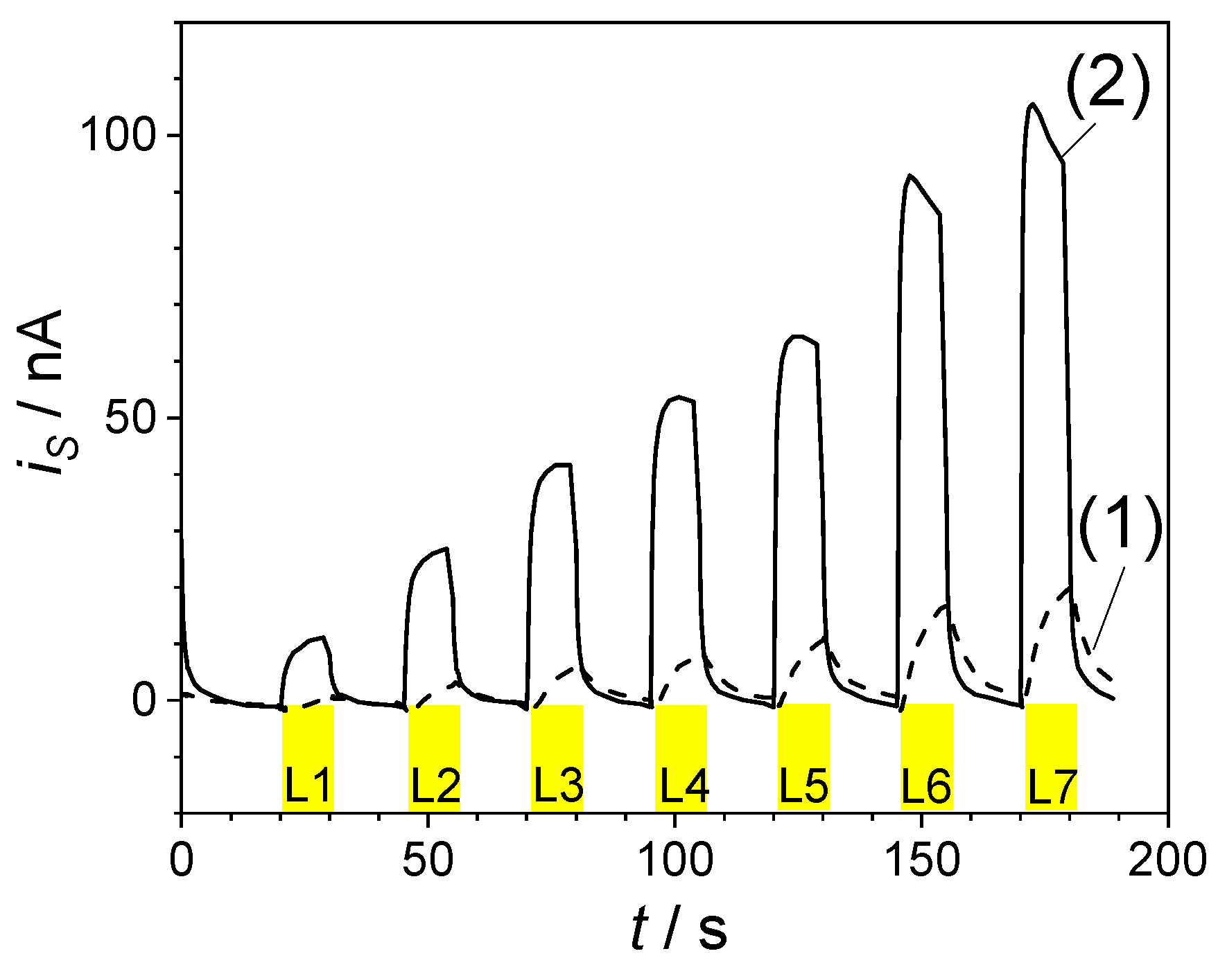
3.2. Transient Photocurrents

Photoinduced processes at sensitized porous semiconductor|electrolyte interface were investigated in literature with transient photocurrents and photovoltages [8,22,23,24,47,48]. For the experiments described below, region of the identical samples from Table S1 (3 and 4 µm thickness) were investigated directly in the SECM cell that had not been used before for approach curves. A similar solution was used as for the SECM approach curves. The photocurrents at the sample are recorded according to the scheme in Figure 3, while the microelectrode is constantly generating [Co(bpy)3]2+ for dye regeneration.
Figure 6 shows the photocurrent transient recorded at a D358- and DN216-TiO2 photoanodes with and without post-TiCl4 treatment. When the light is switched on, the photocurrent rises. The slope is determined by filling the trap states in TiO2. As the trap occupancy is successively increased, the transport processes of eCB in the interconnected TiO2 particles accelerate because the density of unoccupied trap states decreases relative to that of mobile eCB. Higher light intensity also shortens the time until a significant fraction of the traps is filled. This can be qualitatively seen from both traces in Figure 6. The post-TiCl4 treatment is assumed to reduce the density of near-surface trap states. In agreement, the current rise is faster for the sample TiCl4-treated sample at each light intensity. Effects of limited mediator availability have to be considered as well, especially at high light intensity, narrow porous channels, sterically demanding mediator, and low mediator concentrations as used in these experiments [49]. These effects can contribute to a decline after an initial photocurrent spike, which is detected for the TiCl4-treated sample at high light intensities [50,51]. Eventually, the photocurrents reach steady-state values iss under constant illumination. These iss values will be discussed in Section 4.3.

4. Discussion

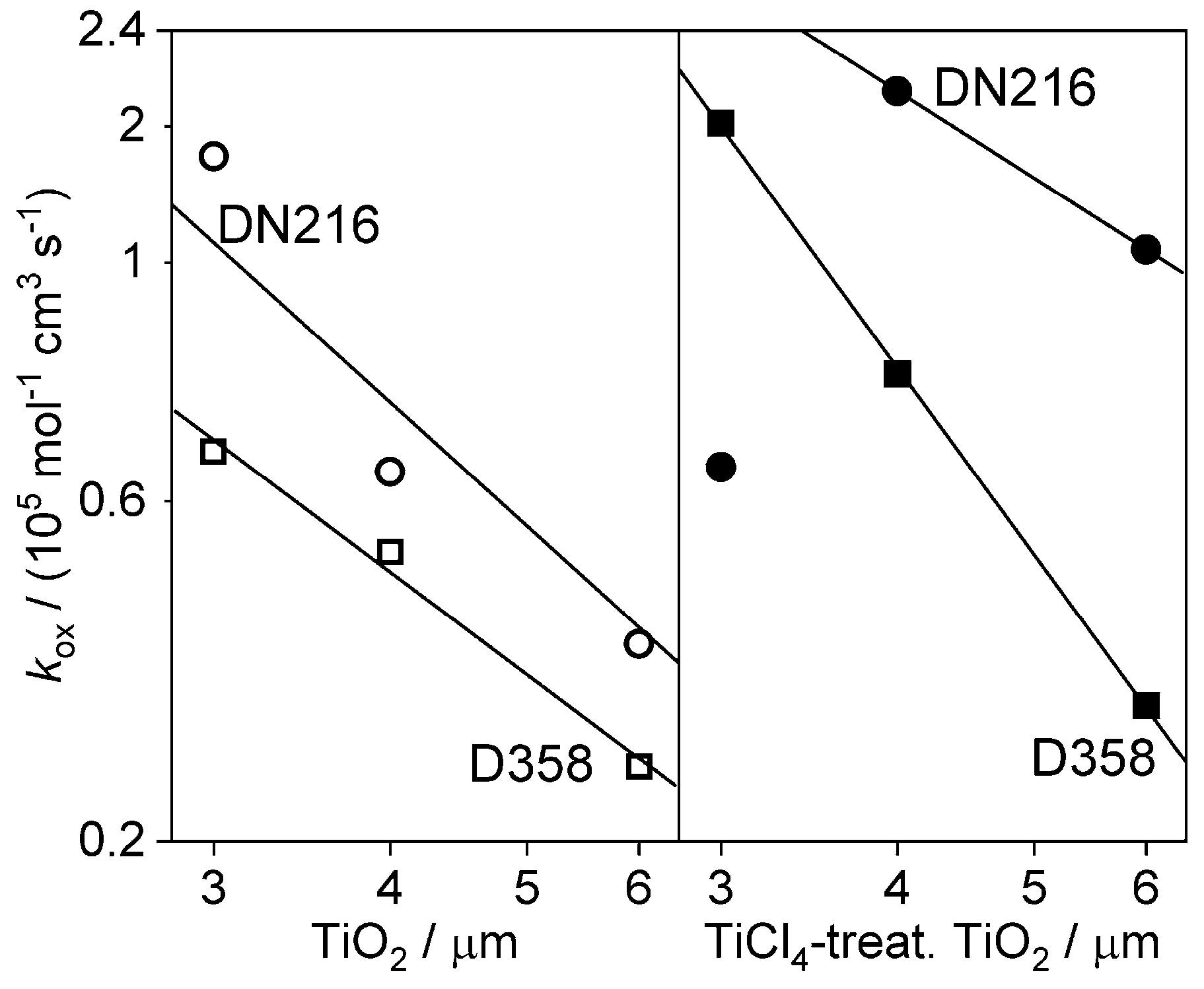
4.1. Determination of Regeneration Rate Constant

A very simplified model that relates structural properties of DSSC photoanodes to their SECM response has been derived before and is summarized by Equation (3) [32].
k eff = Γ D ϕ h v J h v k ox c * k ox + ϕ h v J h v
Here kox [cm3 mol−1 s−1] is the (heterogeneous) bimolecular regeneration rate constant for the reaction in Equation (1), ΓD [mol cm−2] is the dye loading per geometric area evaluated from independent measurements, c* [mol cm−3] is the [Co(bpy)3]3+ mediator bulk concentration, J [mol cm−2 s−1] is the photon flux used to illuminate the samples, and φhv [cm2 mol−1] is the dye excitation cross-section. Fitting the keff-Jhv values to Equation (3) yielded estimates of kox and φhv. The rate constant kox is not an elementary rate constant because individual dye molecules in the porous electrode of finite thickness are potentially exposed to different photon fluxes and different diffusional fluxes of the mediator. For this reason, kox decreased with increasing thickness, because Equation (3) corrects for the higher dye loading with thicker samples but does not correct for the less efficient mediator diffusion to the dye molecules in different depth of the photoanode.
Figure 7 shows the kox values for each photoanodes as a function of the thickness of the porous photoanode. The detailed data set is reported in Tables S4 and S5. The data suggests that the kox steadily decreases as the thickness of the photoanodes increases, as highlighted by the linear fit of the semilogarithmic plot. In this case, the mass transport limitation in thick electrodes [4,5] becomes dominant over the dye-regeneration kinetics and can be particularly strong when the sterically demanding mediator such as [Co(bpy)3]3+ mediator was used [49]. In addition to the porous layer thickness, also the nature of the dye molecule appears to consistently influence the dye-regeneration kinetics. The samples sensitized with the DN216 dye molecule showed a regeneration rate constant kox that was up to 2.4 times higher than the ones recorded over D358-sensitized electrodes despite an almost identical chromophore in DN216 and D358. This was due to the smaller anchoring chain of DN216 which reduces its steric hindrance towards the mediator diffusion inside the porous photoanode. This information covers the role played by the steric hindrance of the dye structural features on the dye regeneration efficiency [9,10].
The post-TiCl4 treatment of TiO2 photoanodes strongly enhanced the dye regeneration rate constant of both, D358- and DN216-sensitized samples, and [Co(bpy)3]3+ as mediator. This effect is due to the inhibition of the ET of eCB to the oxidized form of the mediator and the photo-oxidized dye D+ probably be decreasing the number of near-surface defects that act as traps from which such ET processes can start. The enhanced dye regeneration efficiency as measured by SECM for passivated photoanodes is in line with the results of other working groups that passivate the TiO2 photoanodes for enhancing the DSSCs photovoltaic features [11,12].

4.2. Light-Harvesting Efficiency

The dye absorption cross-section Φ h v is obtained from the fitting of Equation (3) and is used for the calculation of the light-harvesting efficiency according to Lambert-Beer law. All the TiO2 samples show an LHE of 100% which is in agreement with what is commonly reported for TiO2-based photoanodes in literature [52].

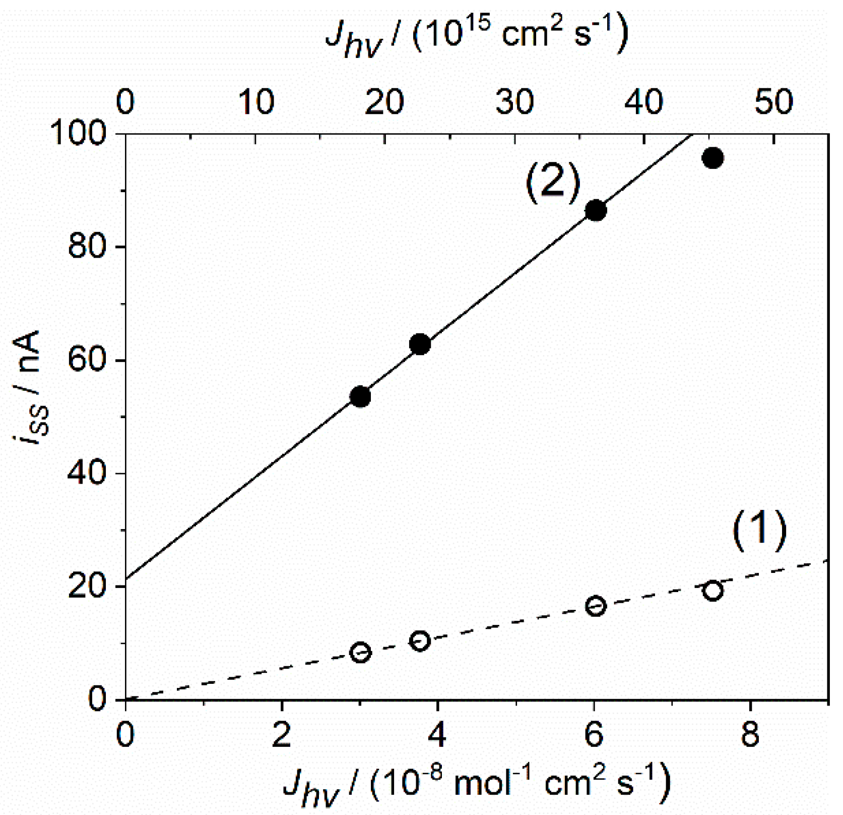
4.3. Transient Photocurrent

Different processes shape the photocurrent transients at different time scales. The rate of the trapping-detrapping transport of eCB in the semiconductor [7,48,53], back electron transfer processes and mediator mass transport from counter electrode to the inner layers of the photoanodes [25] have been reported to influence the current transients in different time regimes. Consequently, the porosity of the electrode [26], the thickness of the porous film [10], and the passivation of the electrode with nanostructures [11] were all reported to exert an influence the photocurrent behavior [38,44]. The transport effects in the electrolyte will become more important when the mediator concentration is lower as it is the case for SECM experiments and the photocurrent transients measured under those conditions.
The data shown in Figure 8 suggested that photoanodes with post-TiCl4 treatment strongly enhance the steady-state photocurrents iss by decreasing the rat of back electron transfer processes compared to untreated TiO2 porous film in agreement with Ref. [20]. These findings are also in agreement with the enhanced dye-regeneration rate constant kox obtained DN216-sensitized TiO2 photoanodes post-TiCl4 treatment from SECM approach curves in the feedback mode.
Figure 9 shows iss as a function of the photoanode thickness and passivation. It appears that the steady-state photocurrent is negligibly affected by the sample thickness at low light intensities. However, iss strongly decreases at high light intensities and in thicker photoanodes as a result of processes 5 and 6 and mediator mass transport limitation compared to thin samples. The mediator diffusion plays a dominant role also in thicker passivated photoanodes, where iss is smaller than the values recorded on thinner samples. Overall, the highest iss values are recorded on 3 µm passivated TiO2 photoanodes. These results are in agreement with a decrease of kox values as a function of increased thickness as reported in Figure 7.

5. Conclusions

This work reports a SECM investigation of the dye regeneration kinetic optimized by passivating the TiO2 photoanodes by the post-TiCl4 treatment as commonly used in dye-sensitized solar cells. The passivation layer is known to improve the charge separation by reducing the density of near-surface trap states, from which back electron transfer processes may commence to the oxidized mediator or the photo-oxidized dye. Therefore, this SECM investigation of the dye-regeneration reaction rate adds valuable information on the overall characterization of the DSSCs. The use of dye molecule with variable steric demand, the structure of which is a source of a hindrance for the mediator diffusion through the porous sensitized film, identify mediator mass transport limitations as a factor influencing the dye-regeneration kinetic. This is also supported by the comparison of several photoanode thicknesses. The analysis of photocurrent transients recorded directly in the SECM cell at sensitized TiO2 photoanodes with and without post-TiCl4 treatment supports the SECM data. In addition to the known effects, the post-TiCl4 treatment decreases the pore diameters slightly. It could be expected that this increases the diffusional hindrance for mediator transport in the mesoporous electrode. However, this effect, if present at all, is overcompensated by the improved charge separation. The SECM method can detect effects on mediator regeneration invoked by small changes in the spacer length such as between the dyes D358 and DN216, where the dye with the shorter spacer and thus less constriction of diffusion path yields higher kox values that contain a contribution from the internal mass transport.

Supplementary Materials

The following are available online at https://www.mdpi.com/2673-3293/1/3/21/s1, SM-1: Experimental details with more parameters of the TiO2-sensitized photoanodes of different thickness, Table S1: TiO2-sensitized photoanodes with variable porous layer thickness, compact blocking layer, passivation by TiO2-NPs, and average dye loading ΓD, SM-2: Details of Fitting the SECM approach curves with approach curves of all D358/TiO2 photoanodes, Figure S1: Approach curves of D358/TiO2 photoanodes with different thicknesses, Figure S2: Approach curves of DN216/TiO2 photoanodes with different thicknesses, SM-3: Determination of the mediator diffusion coefficient from microelectrode cyclic voltammetry, Figure S3: Cyclic voltammogram of [Co(bpy)3](PF6)3+ at the Au microelectrode, SM-4: Details of fitting of SECM approach curves, Table S2: Fitted ĸ and calculated keff per Jhv for the D358/TiO2 electrodes of various thicknesses, Table S3: Fitted ĸ and calculated keff per Jhv for the DN216/TiO2 electrodes of various thicknesses, SM-5: Fitting of the dependce of keff on light intensity, Figure S4: Non-linear fit of keff as function of Jhv, Table S4: Fitting parameters for D358/TiO2 photoanodes, Table S5: Fitting parameters for DN216/TiO2 photoanodes, SM-6: Transient photocurrents, Figure S5: Transient photocurrents recorded at the (a) D358/TiO2, passivated D358/TiO2, DN216/ TiO2, passivated DN216/ TiO2.

Author Contributions

Conceptualization, G.W., A.H., N.V., K.N.; methodology, G.W. and S.S.; software, G.W.; validation, S.S.; sample preparation and structural characterization, K.N.; data analysis, S.S.; writing—original draft preparation, S.S.; writing—review and editing, G.W.; visualization, S.S.; supervision, G.W.; project administration, G.W.; funding acquisition, G.W., A.H. All authors have read and agreed to the published version of the manuscript.

Funding

This research was funded by Deutsche Forschungsgemeinschaft, grant number Wi1617/20 and Swiss National Science Foundation with contract 200020_185041.

Conflicts of Interest

The authors declare no conflict of interest. The funders had no role in the design of the study; in the collection, analyses, or interpretation of data; in the writing of the manuscript, or in the decision to publish the results.

References

  1. O’Regan, B.; Grätzel, M. A low-cost, high-efficiency solar cell based on dye-sensitized colloidal titanium dioxide films. Nature 1991, 353, 737–740. [Google Scholar] [CrossRef]
  2. Yella, A.; Lee, H.-W.; Tsao, H.N.; Yi, C.; Chandiran, A.K.; Nazeeruddin, M.K.; Diau, E.W.-G.; Yeh, C.-Y.; Zakeeruddin, S.M.; Grätzel, M. Porphyrin-Sensitized Solar Cells with Cobalt (II/III)-Based Redox Electrolyte Exceed 12% Efficiency [Erratum to document cited in CA156: 15579]. Science 2011, 334, 1203. [Google Scholar] [CrossRef]
  3. Shockley, W.; Queisser, H.J. Detailed balance limit of efficiency of p-n junction solar cells. J. Appl. Phys. 1961, 32, 510–519. [Google Scholar] [CrossRef]
  4. Snaith, H.J. Estimating the Maximum Attainable Efficiency in Dye-Sensitized Solar Cells. Adv. Funct. Mater. 2010, 20, 13–19. [Google Scholar] [CrossRef]
  5. Grätzel, M. Photoelectrochemical cells. Nature 2001, 414, 338–344. [Google Scholar] [CrossRef] [PubMed]
  6. Tiwana, P.; Docampo, P.; Johnston, M.B.; Snaith, H.J.; Herz, L.M. Electron mobility and injection dynamics in mesoporous ZnO, SnO2, and TiO2 films used in dye-sensitized solar cells. ACS Nano 2011, 5, 5158–5166. [Google Scholar] [CrossRef] [PubMed]
  7. Peter, L. “Sticky Electrons” Transport and Interfacial Transfer of Electrons in the Dye-Sensitized Solar Cell. Acc. Chem. Res. 2009, 42, 1839–1847. [Google Scholar] [CrossRef] [PubMed]
  8. Hagfeldt, A.; Peter, L. Characterization and Modeling of Dye-Sensitized Solar Cells: A Toolbox Approach. In Dye-Sensitized Solar Cells; Kalyanasundaram, K., Ed.; EPFL Press: Lausanne, Switzerland, 2010; pp. 323–402. [Google Scholar]
  9. Hao, Y.; Yang, W.; Karlsson, M.; Cong, J.; Wang, S.; Li, X.; Xu, B.; Hua, J.; Kloo, L.; Boschloo, G. Efficient Dye-Sensitized Solar Cells with Voltages Exceeding 1 V through Exploring Tris(4-alkoxyphenyl)amine Mediators in Combination with the Tris(bipyridine) Cobalt Redox System. ACS Energy Lett. 2018, 3, 1929–1937. [Google Scholar] [CrossRef]
  10. Listorti, A.; O’Regan, B.; Durrant, J.R. Electron Transfer Dynamics in Dye-Sensitized Solar Cells. Chem. Mater. 2011, 23, 3381–3399. [Google Scholar] [CrossRef]
  11. Chandiran, A.K.; Abdi-Jalebi, M.; Nazeeruddin, M.K.; Grätzel, M. Analysis of electron transfer properties of ZnO and TiO2 photoanodes for dye-sensitized solar cells. ACS Nano 2014, 8, 2261–2268. [Google Scholar] [CrossRef] [PubMed]
  12. Nĕmec, H.; Rochford, J.; Taratula, O.; Galoppini, E.; Kuzel, P.; Polívka, T.; Yartsev, A.; Sundström, V. Influence of the electron-cation interaction on electron mobility in dye-sensitized ZnO and TiO2 nanocrystals: A study using ultrafast terahertz spectroscopy. Phys. Rev. Lett. 2010, 104, 197401. [Google Scholar] [CrossRef] [PubMed] [Green Version]
  13. Quintana, M.; Edvinsson, T.; Hagfeldt, A.; Boschloo, G. Comparison of dye-sensitized ZnO and TiO2 solar cells: Studies of charge transport and carrier lifetime. J. Phys. Chem. C 2007, 111, 1035–1041. [Google Scholar] [CrossRef]
  14. Zhang, Z.; Yates Jr, J.T. Band bending in semiconductors: Chemical and physical consequences at surfaces and interfaces. Chem. Rev. 2012, 112, 5520–5551. [Google Scholar] [CrossRef] [PubMed]
  15. Nazeeruddin, M.K.; Kay, A.; Rodicio, I.; Humphry-Baker, R.; Mueller, E.; Liska, P.; Vlachopoulos, N.; Grätzel, M. Conversion of light to electricity by cis-X2bis(2,2’-bipyridyl-4,4’-dicarboxylate)ruthenium(II) charge-transfer sensitizers (X = Cl-, Br-, I-, CN-, and SCN-) on nanocrystalline TiO2 electrodes. J. Am. Chem. Soc. 1993, 115, 6382–6390. [Google Scholar] [CrossRef]
  16. Park, N.-G.; Schlichthörl, G.; van de Lagemaat, J.; Cheong, H.M.; Mascarenhas, A.; Frank, A.J. Dye-Sensitized TiO2 Solar Cells: Structural and Photoelectrochemical Characterization of Nanocrystalline Electrodes Formed from the Hydrolysis of TiCl4. J. Phys. Chem. B 1999, 103, 3308–3314. [Google Scholar] [CrossRef]
  17. Sommeling, P.M.; O’Regan, B.C.; Haswell, R.R.; Smit, H.J.P.; Bakker, N.J.; Smits, J.J.T.; Kroon, J.M.; van Roosmalen, J.A.M. Influence of a TiCl4 post-treatment on nanocrystalline TiO2 films in dye-sensitized solar cells. J. Phys. Chem. B 2006, 110, 19191–19197. [Google Scholar] [CrossRef]
  18. Barbé, C.J.; Arendse, F.; Comte, P.; Jirousek, M.; Lenzmann, F.; Shklover, V.; Grätzel, M. Nanocrystalline Titanium Oxide Electrodes for Photovoltaic Applications. J. Am. Ceram. Soc. 1997, 80, 3157–3171. [Google Scholar] [CrossRef]
  19. Ito, S.; Liska, P.; Comte, P.; Charvet, R.; Péchy, P.; Bach, U.; Schmidt-Mende, L.; Zakeeruddin, S.M.; Kay, A.; Nazeeruddin, M.K.; et al. Control of dark current in photoelectrochemical (TiO2/I-I3−)) and dye-sensitized solar cells. Chem. Commun. 2005, 4351–4353. [Google Scholar] [CrossRef] [Green Version]
  20. O’Regan, B.C.; Durrant, J.R.; Sommeling, P.M.; Bakker, N.J. Influence of the TiCl4 Treatment on Nanocrystalline TiO2 Films in Dye-Sensitized Solar Cells. 2. Charge Density, Band Edge Shifts, and Quantification of Recombination Losses at Short Circuit. J. Phys. Chem. C 2007, 111, 14001–14010. [Google Scholar] [CrossRef]
  21. Zeng, L.-Y.; Dai, S.-Y.; Wang, K.-J.; Pan, X.; Shi, C.-W.; Guo, L. Mechanism of Enhanced Performance of Dye-Sensitized Solar Cell Based TiO2 Films Treated by Titanium Tetrachloride. Chin. Phys. Lett. 2004, 21, 1835–1837. [Google Scholar]
  22. Yella, A.; Mathew, S.; Aghazada, S.; Comte, P.; Grätzel, M.; Nazeeruddin, M.K. Dye-sensitized solar cells using cobalt electrolytes: The influence of porosity and pore size to achieve high-efficiency. J. Mater. Chem. C 2017, 5, 2833–2843. [Google Scholar] [CrossRef]
  23. Zukalová, M.; Zukal, A.; Kavan, L.; Nazeeruddin, M.K.; Liska, P.; Grätzel, M. Organized mesoporous TiO2 films exhibiting greatly enhanced performance in dye-sensitized solar cells. Nano Lett. 2005, 5, 1789–1792. [Google Scholar] [CrossRef] [PubMed]
  24. Ito, S.; Zakeeruddin, S.M.; Humphry-Baker, R.; Liska, P.; Charvet, R.; Comte, P.; Nazeeruddin, M.K.; Pechy, P.; Takata, M.; Miura, H.; et al. High-efficiency organic-dye-sensitized solar cells controlled by nanocrystalline-TiO2 electrode thickness. Adv. Mater. 2006, 18, 1202–1205. [Google Scholar] [CrossRef]
  25. Nusbaumer, H.; Zakeeruddin, S.M.; Moser, J.-E.; Grätzel, M. An Alternative Efficient Redox Couple for the Dye-Sensitized Solar Cell System. Chem. Eur. J. 2003, 9, 3756–3763. [Google Scholar] [CrossRef] [PubMed]
  26. Fan, J.; Hao, Y.; Cabot, A.; Johansson, E.M.J.; Boschloo, G.; Hagfeldt, A. Cobalt(II/III) redox electrolyte in ZnO nanowire-based dye-sensitized solar cells. ACS Appl. Mater. Interfaces 2013, 5, 1902–1906. [Google Scholar] [CrossRef] [PubMed]
  27. Kuang, D.; Wang, P.; Ito, S.; Zakeeruddin, S.M.; Grätzel, M. Stable Mesoscopic Dye-Sensitized Solar Cells Based on Tetracyanoborate Ionic Liquid Electrolyte. J. Am. Chem. Soc. 2006, 128, 7732–7733. [Google Scholar] [CrossRef]
  28. Tsao, H.N.; Comte, P.; Yi, C.; Grätzel, M. Avoiding Diffusion Limitations in Cobalt(III/II)-Tris (2, 2′-Bipyridine)-Based Dye-Sensitized Solar Cells by Tuning the Mesoporous TiO2 Film Properties. ChemPhysChem 2012, 13, 2976–2981. [Google Scholar] [CrossRef]
  29. Tefashe, U.M.; Rudolph, M.; Miura, H.; Schlettwein, D.; Wittstock, G. Photovoltaic characteristics and dye regeneration kinetics in D149-sensitized ZnO with varied dye loading and film thickness. Phys. Chem. Chem. Phys. 2012, 14, 7533–7542. [Google Scholar] [CrossRef]
  30. Rahman, M.; Wei, M.; Xie, F.; Khan, M. Efficient Dye-Sensitized Solar Cells Composed of Nanostructural ZnO Doped with Ti. Catalysts 2019, 9, 273. [Google Scholar] [CrossRef] [Green Version]
  31. Shen, Y.; Nonomura, K.; Schlettwein, D.; Zhao, C.; Wittstock, G. Photoelectrochemical Kinetics of Eosin Y-Sensitized Zinc Oxide Films Investigated by Scanning Electrochemical Microscopy. Chem. Eur. J. 2006, 12, 5832–5839. [Google Scholar] [CrossRef]
  32. Ellis, H.; Schmidt, I.; Hagfeldt, A.; Wittstock, G.; Boschloo, G. Influence of Dye Architecture of Triphenylamine Based Organic Dyes on the Kinetics in Dye-Sensitized Solar Cells. J. Phys. Chem. C 2015, 119, 21775–21783. [Google Scholar] [CrossRef]
  33. Falgenhauer, J.; Richter, C.; Miura, H.; Schlettwein, D. Stable Sensitization of ZnO by Improved Anchoring of Indoline Dyes. ChemPhysChem 2012, 13, 2893–2897. [Google Scholar] [CrossRef] [PubMed]
  34. Ruess, R.; Scarabino, S.; Ringleb, A.; Nonomura, K.; Vlachopoulos, N.; Hagfeldt, A.; Wittstock, G.; Schlettwein, D. Diverging Surface Reactions at TiO2- or ZnO-Based Photoanodes in Dye-Sensitized Solar Cells. Phys. Chem. Chem. Phys. 2019, 21, 13047–13057. [Google Scholar] [CrossRef]
  35. Kozma, E.; Concina, I.; Braga, A.; Borgese, L.; Depero, L.E.; Vomiero, A.; Sberveglieri, G.; Catellani, M. Metal-free organic sensitizers with a sterically hindered thiophene unit for efficient dye-sensitized solar cells. J. Mater. Chem. 2011, 21, 13785. [Google Scholar] [CrossRef]
  36. Cao, Y.; Cai, N.; Wang, Y.; Li, R.; Yuan, Y.; Wang, P. Modulating the assembly of organic dye molecules on titania nanocrystals via alkyl chain elongation for efficient mesoscopic cobalt solar cells. Phys. Chem. Chem. Phys. 2012, 14, 8282–8286. [Google Scholar] [CrossRef] [PubMed]
  37. Ham, H.W.; Kim, Y.S. Theoretical study of indoline dyes for dye-sensitized solar cells. Thin Solid Films 2010, 518, 6558–6563. [Google Scholar] [CrossRef]
  38. Murakami, T.N.; Koumura, N.; Kimura, M.; Mori, S. Structural effect of donor in organic dye on recombination in dye-sensitized solar cells with cobalt complex electrolyte. Langmuir 2014, 30, 2274–2279. [Google Scholar] [CrossRef]
  39. Feldt, S.M.; Gibson, E.A.; Gabrielsson, E.; Sun, L.; Boschloo, G.; Hagfeldt, A. Design of Organic Dyes and Cobalt Polypyridine Redox Mediators for High-Efficiency Dye-Sensitized Solar Cells. J. Am. Chem. Soc. 2010, 132, 16714–16724. [Google Scholar] [CrossRef]
  40. García-Rodríguez, R.; Jiang, R.; Canto-Aguilar, E.J.; Oskam, G.; Boschloo, G. Improving the mass transport of copper-complex redox mediators in dye-sensitized solar cells by reducing the inter-electrode distance. Phys. Chem. Chem. Phys. 2017, 19, 32132–32142. [Google Scholar] [CrossRef]
  41. Heiniger, L.-P.; Giordano, F.; Moehl, T.; Grätzel, M. Mesoporous TiO2 Beads Offer Improved Mass Transport for Cobalt-Based Redox Couples Leading to High Efficiency Dye-Sensitized Solar Cells. Adv. Energy Mater. 2014, 4, 1400168. [Google Scholar] [CrossRef]
  42. Tefashe, U.M.; Nonomura, K.; Vlachopoulos, N.; Hagfeldt, A.; Wittstock, G. Effect of Cation on Dye Regeneration Kinetics of N719-Sensitized TiO2 Films in Acetonitrile-Based and Ionic-Liquid-Based Electrolytes Investigated by Scanning Electrochemical Microscopy. J. Phys. Chem. C 2012, 116, 4316–4323. [Google Scholar] [CrossRef]
  43. Nunes Kirchner, C.; Hallmeier, K.H.; Szargan, R.; Raschke, T.; Radehaus, C.; Wittstock, G. Evaluation of Thin Film Titanium Nitride Electrodes for Electroanalytical Applications. Electroanalysis 2007, 19, 1023–1031. [Google Scholar] [CrossRef]
  44. Feldt, S.M.; Lohse, P.W.; Kessler, F.; Nazeeruddin, M.K.; Grätzel, M.; Boschloo, G.; Hagfeldt, A. Regeneration and recombination kinetics in cobalt polypyridine based dye-sensitized solar cells, explained using Marcus theory. Phys. Chem. Chem. Phys. 2013, 15, 7087–7097. [Google Scholar] [CrossRef] [PubMed]
  45. Cornut, R.; Lefrou, C. New analytical approximation of feedback approach curves with a microdisk SECM tip and irreversible kinetic reaction at the substrate. J. Electroanal. Chem. 2008, 621, 178–184. [Google Scholar] [CrossRef]
  46. Tefashe, U.M.; Loewenstein, T.; Miura, H.; Schlettwein, D.; Wittstock, G. Scanning electrochemical microscope studies of dye regeneration in indoline (D149)-sensitized ZnO photoelectrochemical cells. J. Electroanal. Chem. 2010, 650, 24–30. [Google Scholar] [CrossRef]
  47. Cao, F.; Oskam, G.; Searson, P.C. Electron Transport in Porous Nanocrystalline TiO2 Photoelectrochemical Cells. J. Phys. Chem. 1996, 100, 17021–17027. [Google Scholar] [CrossRef]
  48. Walker, A.B.; Peter, L.M.; Martínez, D.; Lobato, K. Transient Photocurrents in Dye-Sensitized Nanocrystalline Solar Cells. Chimia 2007, 61, 792–795. [Google Scholar] [CrossRef]
  49. Nelson, J.J.; Amick, T.J.; Elliott, C.M. Mass Transport of Polypyridyl Cobalt Complexes in Dye-Sensitized Solar Cells with Mesoporous TiO2 Photoanodes. J. Phys. Chem. C 2008, 112, 18255–18263. [Google Scholar] [CrossRef]
  50. Guillen, E.; Peter, L.M.; Anta, J.A. Electron Transport and Recombination in ZnO-Based Dye-Sensitized Solar Cells. J. Phys. Chem. C 2011, 115, 22622–22632. [Google Scholar] [CrossRef]
  51. Keis, K.; Vayssieres, L.; Rensmo, H.; Lindquist, S.-E.; Hagfeldt, A. Photoelectrochemical Properties of Nano- to Microstructured ZnO Electrodes. J. Electrochem. Soc. 2001, 148, A149–A155. [Google Scholar] [CrossRef]
  52. Tachibana, Y.; Hara, K.; Sayama, K.; Arakawa, H. Quantitative Analysis of Light-Harvesting Efficiency and Electron-Transfer Yield in Ruthenium-Dye-Sensitized Nanocrystalline TiO2 Solar Cells. Chem. Mater. 2002, 14, 2527–2535. [Google Scholar] [CrossRef]
  53. Bisquert, J.; Vikhrenko, V.S. Interpretation of the Time Constants Measured by Kinetic Techniques in Nanostructured Semiconductor Electrodes and Dye-Sensitized Solar Cells. J. Phys. Chem. B 2004, 108, 2313–2322. [Google Scholar] [CrossRef]
Figure 1. Schematic structure and electron loss processes in dye sensitized photoanodes without and with TiCl4-treament. Desired (forward) processes are in blue, unwanted (backward) processes are in red; (1) Light absorption by the dye; (2) electron injection of photo-excited dye into the conduction band of TiO2, (3) electron transport by trap-diffusion process, (4) dye regeneration by electron transfer from reduced form of the mediator, (5) back electron transfer from TiO2 conduction band to the oxidized form of the mediator, (6) back electron transfer from TiO2 conduction band to the photo-oxidized dye molecule; (7) electron transfer from the back contact to the oxidized form of the mediator; (8) electron transfer from the back contact to a photo-oxidized dye molecule. The processes 5′ and 6′ denote corresponding processes starting from a trap state near the surface. Abbreviations; BL, blocking layer; TCO, transparent conducting oxide (back contact); D/D*D*, dye/ photo-excited dye/ photo-oxidized dye; R/O, reduced/oxidized form of the redox mediator (also as , /-). The top row shows a schematic sketch, the lower row and simplified energy diagram of the solid|liquid interface.
Electrochem 01 00021 g001
Figure 2. Structure of D358 and DN216. The phenylene donor group is shown in blue, the p-linker in red, and the acceptor rhodamine in green.
Electrochem 01 00021 g002
Figure 3. Schematic setup for the scanning electrochemical microscopy (SECM) experiment. For the measurement of transient photocurrents, the light was manipulated by the shutter.
Electrochem 01 00021 g003
Figure 4. Normalized SECM feedback mode towards (a) 4 µm thick D358/TiO2 electrode without and (b) with post-TiCl4 treatment, and (c) 4 µm thick DN216/TiO2 without and (d) with post-TiCl4 treatment; in 0.1 mM [Co(bpy)3](PF6)3 + 0.1 M TBAPF6 in acetonitrile. Lines are fitted curves according to the model described in SM-2 [45]; dfilm = 4 µm; Au microelectrode rT = 28.85 µm, ET = −0.15 V, vT = 1 µm s−1; illumination at 455 nm with Jhv in 10−7 mol cm−2 s−1 of (0) dark, (1) 0.05, (2) 0.12, (3) 0.19, (4) 0.24, (5) 0.32, (6) 0.51, (7) 0.64, (8) 1.93. The intensities in 1015 cm−2 s−1 are 3.0, 7.2, 11, 14, 19, 31, 38, 116.
Electrochem 01 00021 g004
Figure 5. Plot of experimental keff vs. J for (1 -) D358/TiO2 4 µm, (2 , ) D358/TiO2 4 µm with post-TiCl4 treatment, (3 8) DN216/TiO2 6 µm, and (4 7) like DN216/TiO2 6 µm but with post-TiCl4 treatment. Solution 0.1 mM [Co(bpy)3](PF6)3 + 0.1 M TBAPF6 in acetonitrile. The keff values were derived from the fitting of the approach curves in Figures S2 and S3 to the model in SM-2. The solid lines in Figure 5 were derived from Equation (3) and fitting parameters are detailed in SM-4.
Electrochem 01 00021 g005
Figure 6. Transient photocurrents recorded at (1) 4 µm thick DN216/TiO2 electrode without and (2) with post-TiCl4 treatment; in 0.2 mM [Co(bpy)3](PF6)3 + 0.1 M TBAPF6 in acetonitrile under on-off light cycles of light intensity in 108 mol cm2 s1 of (L1) 0.76, (L2) 1.51, (L3) 2.26, (L4) 3.01, (L5) 3.77, (L6) 6.02 and (L7) 7.52. The intensity in 1015 cm−2 s−1 are 4.58, 9.09, 13.6, 18.1, 22.7, 36.3 and 45.3. Further details in SM-6.
Electrochem 01 00021 g006
Figure 7. Plot of kox for (∀) D358- and () DN216-TiO2 photoanodes and (b) (!) D358- and ( , ) DN216-TiO2 photoanodes with post-TiCl4 treatment of variable thicknesses in 0.1 mM [Co(bpy)3](PF6)3 + 0.1 M TBAPF6 in acetonitrile. The kox values were obtained from fitting of Equation (3), which is further detailed in SM-6.
Electrochem 01 00021 g007
Figure 8. Plot of steady-state photocurrent iSS under constant illumination, as a function of light intensity Jhv for (1 -) 4 µm DN216/TiO2, and (2 , ) 4 µm DN216 on post-TiCl4 treated TiO2. The lines are linear fits.
Electrochem 01 00021 g008
Figure 9. Plot of steady-state photocurrent iSS as a function of porous film thickness and post-TiCl4 treatment for DN216/TiO2, recorded for light intensity in 10−8 mol cm−2 s−1 of (1) 0.76, (2) 1.51, (3) 2.26, (4) 3.01, (5) 3.77, (6) 6.02 and (7) 7.52. The intensities in 1015 cm−2 s−1 are 4.58, 9.09, 13.6, 18.1, 22.7, 36.3 and 45.3.
Electrochem 01 00021 g009

