Article

Carbon-α-Fe2O3 Composite Active Material for High-Capacity Electrodes with High Mass Loading and Flat Current Collector for Quasi-Symmetric Supercapacitors

1
Smart Materials, Istituto Italiano di Tecnologia, Via Morego 30, 16163 Genova, Italy
2
Dipartimento di Informatica Bioingegneria, Robotica e Ingegneria dei Sistemi (DIBRIS), Università Degli Studi di Genova, Via All’Opera Pia 13, 16145 Genova, Italy
3
BeDimensional S.p.A., Via Lungotorrente Secca 30R, 16163 Genova, Italy
4
Center for Nano Science and Technology@PoliMi, Istituto Italiano di Tecnologia, Via Pascoli 70/3, 20133 Milano, Italy
5
Graphene Labs, Istituto Italiano di Tecnologia, Via Morego 30, 16163 Genoa, Italy
6
Materials Characterization Facility, Istituto Italiano di Tecnologia, Via Morego 30, 16163 Genova, Italy
7
Electron Microscopy Facility, Istituto Italiano di Tecnologia, Via Morego, 30, 16163 Genova, Italy
8
Department of Mechanical Engineering–DIME, University of Genoa, 16145 Geova, Italy
*
Author to whom correspondence should be addressed.
Electrochem 2022, 3(3), 463-478; https://doi.org/10.3390/electrochem3030032
Submission received: 22 June 2022 / Revised: 11 August 2022 / Accepted: 17 August 2022 / Published: 23 August 2022
(This article belongs to the Special Issue Feature Papers in Electrochemistry)

Abstract

:
In this work, we report the synthesis of an active material for supercapacitors (SCs), namely α-Fe2O3/carbon composite (C-Fe2O3) made of elongated nanoparticles linearly connected into a worm-like morphology, by means of electrospinning followed by a calcination/carbonization process. The resulting active material powder can be directly processed in the form of slurry to produce SC electrodes with mass loadings higher than 1 mg cm−2 on practical flat current collectors, avoiding the need for bulky porous substrate, as often reported in the literature. In aqueous electrolyte (6 M KOH), the so-produced C-Fe2O3 electrodes display capacity as high as ~140 mAh g−1 at a scan rate of 2 mV s−1, while showing an optimal rate capability (capacity of 32.4 mAh g−1 at a scan rate of 400 mV s−1). Thanks to their poor catalytic activity towards water splitting reactions, the electrode can operate in a wide potential range (−1.6 V–0.3 V vs. Hg/HgO), enabling the realization of performant quasi-symmetric SCs based on electrodes with the same chemical composition (but different active material mass loadings), achieving energy density approaching 10 Wh kg−1 in aqueous electrolytes.

1. Introduction

Supercapacitors (SCs) are electrochemical energy storage systems that can drastically reduce or even eliminate the use of critical raw materials as compared with current market-dominating technologies [1], including Li-ion batteries (LiBs) [2]. As a major drawback, the energy density of commercially available SCs (typically between 5 and 10 Wh kg−1), namely electrochemical double layer capacitors based on activated carbon-based electrodes and organic electrolytes, is lower than batteries (e.g., >100 Wh kg−1 for LiBs) [3]. In this context, pseudocapacitive materials, for example, transition-metal chalcogenides/hydroxides/oxides [4,5,6] and conducting polymers [7,8], can offer nonlinear energy storage contributions associated with the reversible surface or near-surface or intercalation Faradaic reactions [9,10,11,12]. These Faradaic contributions can improve the capacity of traditional carbonaceous electrodes based on activated carbons, while overcoming the mass transfer limitations of batteries [9], thus, “unifying” purely electrostatic phenomenon with Faradaic mechanisms at a nanoscale [13]. A major drawback of pseudocapacitive materials is the low electric conductivity, which results in poor rate performances [14,15]. Even though excellent energy density vs. power density performances have been widely reported in the literature [9,10,11,12], these results are commonly achieved using low mass loading of active materials (<1 mg cm−2) [16] or using bulky and heavy conductive substrates (e.g., Ni foams) [9]. In both cases, the mass and volume of nonactive materials composing the cells represent more than 10 times those of the active materials [17], indicating that it is still challenging to design “practical” pseudocapacitors with high-energy density at the cell level [18]. To solve these issues, active material nanostructuring and compounding are universal strategies to increase the electrochemically accessible surface area of SC active materials, guaranteeing short ion-diffusion lengths and fast redox reaction kinetics [12,19], as well as optimal electrical conductivity [15,18]. In this scenario, iron oxides represent a class of promising active materials for negative electrodes in asymmetric SCs [16,20]. In particular, α-Fe2O3 is an environmentally friendly and low-cost abundant pseudocapacitive material that stably operates in alkaline electrolytes with a large theoretical capacity up to ~1 Ah g−1 (over 1 V potential window) [16,21], which originates from the reversible oxidation/reduction of Fe3+ and Fe2+ states [16,21]. Because of its insufficient electrical conductivity (~10−14 S cm−1) [16,21], it is pivotal to find scalable strategies to synthesize α-Fe2O3 in nanostructured forms that can be effectively integrated into conductive scaffolds [21,22,23], while limiting capacity decays caused by volume expansion of the material over subsequent charge–discharge (CD) cycles [16,18,21].
In this work, we report the synthesis of carbon/α-Fe2O3 composite (C-Fe2O3) active material made of elongated nanoparticles linearly connected into a worm-like morphology. The active material synthesis follows a scalable three-step method, including (i) preparation of Fe-based composite fibers through electrospinning of a polymer, Fe salt solution, (ii) pre-oxidation of the resulting fibers at 230 °C in ambient atmosphere, and (iii) calcination-carbonization of pre-oxidized fibers at 600 °C in inert Ar atmosphere. The resulting active material powder can be directly processed in the form of slurry to produce SC electrodes on a flat current collector (avoiding bulky substrates, e.g., Ni foam and carbon fiber clothes) with mass loadings higher than 1 mg cm−2. In aqueous electrolyte (6 M KOH), the so-produced C-Fe2O3 electrodes display capacity as high as ~140 mAh g−1 at a scan rate of 2 mV s−1, while showing an optimal rate capability (capacity of 32.4 mAh g−1 at scan rate of 400 mV s−1). Thanks to the poor catalytic activity of C-Fe2O3 towards water splitting reactions, our electrodes can operate in a wide potential range (−1.6 V–0.3 V vs. Hg/HgO). This wide potential window enables the realization of quasi-symmetric cell configurations based on electrodes with the same chemical composition, but different active material loadings. Our C-Fe2O3-based SCs can compete with more complex asymmetric SCs in terms of electrochemical performance, while representing a cost-effective solution for aqueous SCs.

2. Materials and Methods

Preparation of C-Fe2O3 Active Material
Fe-based composite fibers were fabricated using the electrospinning technique. Firstly, polyacrylonitrile (PAN) (average Mw 150.000, Sigma Aldrich, Darmstadt, Germany) and poly(methyl methacrylate) (PMMA) (average Mw 966.000, Sigma Aldrich, Darmstadt, Germany) were dissolved in N,N-dimethylformamide (DMF) (99.8%, Sigma Aldrich, Darmstadt, Germany) to reach 5 mL of 10 wt% PAN/PMMA (70:30 wt/wt) solution. The latter was stirred for 3 h at 50 °C. Then, 0.1 g of iron(II) acetate tetrahydrate (C4H14FeO8) (95%, Sigma Aldrich, Darmstadt, Germany) was dissolved in the as-prepared solution. After 6 h of continuous magnetic stirring at 50 °C, the resulting solution was suctioned into the electrospinning injector (NE-1000, New Era Pump Systems, Inc., New York, NY, USA), and the electrospinning process was started at a flow rate of 0.1 mL h−1 while applying 23 kV. The distance between the collecting plate and the spinning nozzle was 20 cm and the relative humidity inside the chamber was kept at 45% during the spinning process. The electrospun fibers were pre-oxidized at 230 °C for 1.5 h (heating rate of 5 °C min−1) in ambient atmosphere. This treatment stabilizes the fibers, so that they can be exposed to the subsequent high-temperature carbonization process. Subsequently, the pre-oxidized fibers were calcined/carbonized at 600 °C for 2 h (heating rate of 5 °C min−1), using a three-zone split furnace (PSC 12/600H, Lenton, Hope, UK). The pressure of the chamber was set to 20 Torr via a homemade valve-controlling system, keeping a 100 sccm flow of O2 (15):Ar (85) gas mixture, as controlled upstream through an array of mass flow controllers (1479A, MKS Instruments, Andover, MA, USA). After the treatment, the furnace was left to cool to room temperature.
Material Characterization
Bright-field transmission electron microscopy (BF-TEM) analyses were performed with a JEM-1011 (JEOL, Tokyo, Japan) TEM (thermionic W filament), operating at 100 kV. Scanning TEM-coupled energy dispersive X-ray spectroscopy (STEM-EDS) analyses were carried out on an image-Cs-corrected JEOL (Tokyo, Japan) JEM-2200FS TEM (Schottky emitter), operated at 200 kV, equipped with a Bruker (Billerica, MA, USA) EDS system based on a silicon-drift detector (XFlash 5060). The elemental maps shown here were obtained by integration of thin spectrum ranges corresponding to X-ray series of interest for each mapped region. For the STEM-EDS analyses, a small volume of the active material suspended in ethanol was drop-cast onto a holey carbon-coated Cu grid. The Cu signal in EDS spectra is due to X-rays emitted by the Cu grid hit by backscattered electrons. Scanning electron microscopy (SEM) analysis of the active material was carried out using a JSM-7500FA (JEOL, Tokyo, Japan) equipped with a cold FEG, operated at 10 kV accelerating voltage. The SEM-coupled EDS (SEM-EDS) analyses were performed using an Oxford Instruments (Abingdon, UK) X-Max system with an active area of 80 mm2. The X-ray diffraction (XRD) pattern of C-Fe2O3 active material was collected on a Panalytical (Malvern, UK) Empyrean X-ray diffractometer with a 1.8 kW Cu Kα ceramic X-ray tube, PIXcel3D 2 × 2 mm2 area detector, and operating at 45 kV and 40 mA. The diffraction pattern was performed at ambient conditions in a parallel-beam geometry and symmetric reflection mode over an angular range of 23–70°, with a step size of 0.05°. High Score 4.1 software from Panalytical Malvern (Malvern, UK) was used for phase identification. Raman spectroscopy measurements were performed using a Renishaw (Wotton-under-Edge, UK) microRaman Invia 1000 mounting a 50× objective, with an excitation wavelength of 514 nm and an incident power of 1 mW. The X-ray photoelectron spectroscopy (XPS) analysis was performed by means of a Kratos Axis UltraDLD spectrometer (Kratos Analytical, Manchester, UK) using a monochromatic Al Kα source. The spectra were analyzed using the CasaXPS software. The Fourier-transform infrared spectroscopy (FT-IR) spectra were acquired with a Fourier transform infrared spectrometer (Equinox 70 FT-IR, Bruker, Billerica, MA, USA) with MIRacle attenuated total reflectance (ATR) (PIKE Technologies, Fitchburg, MA, USA). All spectra were recorded in the range between 4000 and 400 cm−1, with a resolution of 4 cm−1, accumulating 64 scans. Inductively coupled plasma optical emission spectroscopy (ICP-OES) measurements were carried out on a Thermo Scientific (Waltham, MA, USA) iCAP 6500 Thermo spectrometer to measure Fe content in the active material. The samples were prepared by dissolving 5.2 mg of C-Fe2O3 in HCl/HNO3 3:1, v/v) for 18 h for digestion. The resulting solution was then diluted to 25 mL with Milli-Q water. The ICP-OES measurements were affected by a systematic error of ca. 5%. The thermal stability of the active materials was investigated by thermogravimetric analysis (TGA) using DISCOVERY SDT650 (TA Instruments, New Castle, DE, USA). The TGA measurements were carried out in air, in the 30–1000 °C temperature range, using a heating rate of 10 °C min1. Specific surface area and porosity measurements were carried out by N2 physisorption at 77 K with an automated gas sorption analyzer (AutoSorb iQ, Quantachrome Instruments, Boynton Beach, FL, USA). Before measurements, the sample was outgassed at 250 °C for 3 h under vacuum conditions to remove any adsorbed species. The specific surface area was calculated using the multi-point Brunauer−Emmett−Teller (BET) method [24,25], considering equally spaced points in the P/P0 range from 0.05 to 0.30 with a correlation coefficient of above 0.999. Pore-size distribution and pore volume were determined by the Barrett−Joyner−Halenda (BJH) method to the desorption branch of the isotherms.
Electrode and SC Fabrication
C-Fe2O3 active materials were mixed with few-layer graphene (BeDimensional S.p.A.), produced by wet-jet milling exfoliation of graphite without any further purification [24,25] and acting as conductive additive [26,27] and polyolefin-grafted acrylic acid copolymer (MTI corp.), acting as binder, with a 85:10:5 weight ratio in water (solid content concentration of ca. 0.3 g L−1) until a homogeneous slurry was obtained. The electrodes were prepared by depositing the as-prepared slurry onto graphite paper (Papyex Flexible Graphite, Mersen, La Défense, France) by doctor blading using an MSK-AFA-H200A coater (MTI Corporation, Richmond, VA, USA). The resulting electrode films were dried in a vacuum oven (Binder, VD 53-UL, BINDER GmbH, Tuttlingen, Germany), at 80 °C overnight to remove water residuals. The mass loading of the electrodes was higher than 1 mg cm−1, approaching those of electrodes in commercially available SCs (as rule of thumb, the weight of active material in commercial SCs accounts for more than 30% of the total mass of the packaged device) [17]. The electrodes were characterized in 6 M KOH aqueous electrolyte using a PTFE-based 3 electrode cell configurations. A 4.24 M KOH-filled Hg/HgO and Pt wire were used as the reference and counter electrodes, respectively. Symmetric SCs were fabricated by stacking two electrodes in a Swagelok-type cell based on 316L stainless steel pistons, a PTFE insulating body, and fluorelastomer sealing rings, using a fiber membrane (Whatman, Maidstone, UK) as the separator. For quasi-symmetric SCs, the mass loading of the electrodes was varied to balance capacities of the positive and negative electrodes over their corresponding operating potential ranges.
Electrochemical Characterization
The electrochemical measurements were carried out using a multi-channel potentiostat/galvanostat (VMP3, Biologic, Seyssinet-Pariset, France), equipped with a current booster unit (±10 A, Biologic). Linear sweep voltammetry (LSV) measurements were carried out on our electrodes to assess their electrochemical stability window. Cyclic voltammetry (CV) measurements were performed on the electrodes and SCs at various potential/voltage scan rates, ranging from 2 to 400 mV s−1. Galvanostatic CD measurements of the SCs were acquired at different current densities, ranging from 0.02 to 50 A g−1. Three-electrode cell configuration measurements were also performed using positive (or negative) and negative (or positive) electrodes as the working and counter electrodes, respectively, and a 4.24 M KOH-filled Hg/HgO as the reference electrode.
The specific capacity (Ah g−1) of the electrodes was calculated from their CV curves as [28,29,30]:
s p e c i f i c   c a p a c i t y = 0.5   I ( V ) d V 3600 × ( ν ) × m
where   I ( V ) dV   is the integrated area of the CV curve (A × V), ν (V s−1) is the potential scan rate, and m (g) is the total mass of the electrode (excluding the current collector). The I⁄m ratio is referred as specific current.
The specific capacity of the electrode was converted to an effective capacitance (Ceff) (F g−1), i.e., the capacitance of a purely capacitive electrode with an equivalent capacity, by:
C e f f = s p e c i f i c   c a p a c i t y × 3600 V  
in which ∆V (V) is the potential window of the electrode.
For the entire SCs, the specific capacity was determined from their galvanostatic CD curves as [28,29]:
s p e c i f i c   c a p a c i t y = ( I × t ) 3600 × m  
where ∆t (s) is the discharge time and m (g) is the total mass of the two electrodes.
The discharge energy density (Wh kg−1), or discharge specific energy (hereafter referred just as energy density), of the SCs was determined using the following integral equation that considered the nonlinearity of galvanostatic discharge characteristics [28,29,31]:
( d i s c h a r g e )   e n e r g y   d e n s i t y = | I | × t ( V m a x ) t ( V m i n = 0 ) V ( t ) d t 3.6 × m  
where V(t) is the cell voltage (V) as a function of time (s), while t(Vmax) and t(Vmin = 0) are the moments in time corresponding to the maximum and minimum cell voltages (Vmax and Vmin), respectively. The charge energy density is calculated similarly to the discharge energy density, except that the integral is calculated over the galvanostatic charge characteristic (i.e., from t(Vmin = 0) to t(Vmax)).
The discharge power density (W kg−1), or specific power (hereafter referred just as power density) of the SCs was calculated by [28,29]:
( d i s c h a r g e )   p o w e r   d e n s i t y = e n e r g y   d e n s i t y × 3600 t D  
where tD (s) is the discharge time extrapolated from the galvanostatic CD curve used for the determination of the energy density.
The coulombic efficiency (CE) of the SCs was calculated by the ratio of the tD and charge time (tC) of the galvanostatic CD curve, i.e., [28,29]:
C E = t D t C
The capacities of the electrodes were balanced according to:
C+ × m+ = C × m
where C+ and C are the specific capacities of the positive and negative electrodes, respectively, while m+ and m are the masses of positive and negative electrodes (excluding the masses of their current collectors).

3. Results

As shown in Scheme 1, the synthesis of our C-Fe2O3 active material combines the electrospinning of Fe salt/polymer composite with a thermal treatment (pre-oxidation followed by calcination in Ar atmosphere) of electrospun fibers.
Electrospinning is an effective technique for the fabrication of fine fibres of several materials, including polymeric composites, as well as inorganic materials [32]. In our case, the process starts by pumping a PAN/PMMA/C4H14FeO8 solution in DMF, while creating an electric field via imposing a voltage between the collecting plate and the spinning nozzle. Since the electrostatic repulsion of the charges accumulated at the surface of the solution overcome the surface tension of the liquid, the liquid meniscus is transformed into a Taylor cone, and a charged liquid jet is ejected towards the collecting plate [32]. Since the solvent evaporates from the whipping motion occurring during its flying time from the Taylor cone to the collecting plates, solid fibres are formed and finally deposited on the collecting plate in form of a non-woven mat [32]. To produce our active materials, the so-produced fibres are then annealed following a two-step protocol. First, a pre-oxidation step at 230 °C for 1.5 h in open air is carried out to stabilize PAN into the thermally stable ladder-like polymeric structure by means of dehydrogenation and intracyclization reactions [33,34]. Meanwhile, PMMA progressively decomposes into gaseous products via depolymerization, random scission, and side/terminal-group elimination [35,36,37]. The volatile gaseous products leak out the electrospun fibres forming microporous structures [38]. Secondly, the pre-oxidized fibres are calcined/carbonized at 600 °C for 2.5 h in an O2/Ar (15:85 vol/vol) atmosphere. Previous studies in the literature have indicated that an insufficient supply of oxygen can effectively remove hydrogen from organic matter, leading to chars and/or black carbon that reduce reactivity to oxygen [39]. Thus, the pre-oxidized PAN is partially carbonized, while metal precursors evolve into metal oxide colloids (PMMA is, instead, completely decomposed, promoting pore formation) [35,36,37]. As shown by BF-TEM imaging (Figure 1a), the synthesized powder consists of elongated nanoparticles with a sub-µm size and linearly connected into a worm-like morphology, forming porous fibre tangles. Figure 1b reports the SEM image of the as-synthesized powder, confirming the morphology observed in the TEM images. The STEM-EDS characterization (Figure 1c–f) revealed the presence of Fe, O, and C, with a C/Fe atomic ratio (measured on a region of the material suspended on vacuum) of 0.13. We notice that other regions displayed even lower C content (data not shown). Meanwhile, the Fe/O atomic ratio was found to be ca. 1. Figure S1 reports the SEM-EDS analysis of a C-Fe2O3 film, revealing the main presence of Fe and O in the sample.
Considering that the quantification of light elements (i.e., C and O in our case) through EDS may be underestimated as compared with heavy elements (i.e., Fe in our case), the synthesized active material was further characterized through XRD, Raman spectroscopy, FT-IR spectroscopy, ICP-OES, and TGA measurements. As shown in Figure 2a, the positions of the diffraction peaks of the material match those of α-Fe2O3 (ICSD card 98-002-2505), whose lattice parameters are a = 0.50 nm and c = 1.39 nm [40]. The material also exhibits seven characteristic Raman peaks (Figure 2b) indexed to α-Fe2O3 [41,42], as predicted by the group theory of corundum structure of α-Fe2O3 (crystal space group D63d) [42,43]. The peaks are 2A1g (226 and 501 cm−1) and 5Eg (246, 292, 299, 411, and 611 cm−1). The peak at 299 cm−1 is observed as a shoulder of the more intense peak at 292 cm−1, in agreement with the previous literature [41,42]. The peak at 657 cm−1 is associated with Eu mode. Even though Eu is a Raman-forbidden mode, it can arises from inherent crystalline disorder in the crystal lattice of α-Fe2O3 [44,45], including the presence of surface defects and/or reduced grain size [46,47]. In addition, the intense peak at 1313 cm−1 represents the overtone of Eu (i.e., 2Eu), whose high intensity has been associated with the matching between the laser excitation wavelength and an optical transition of α-Fe2O3 [48]. The slightly visible peaks over 1500 cm−1 are associated with the two-magnon scattering that originates from the interaction of two magnons created on antiparallel close spin sites [43,48,49]. Noteworthy, carbonaceous species were not clearly detected by Raman spectroscopy, as shown in Figure S2 by examining the spectral region of the vibrational modes of graphitic species. This indicates that C is present in poorly crystalline phases. The FT-IR spectra of carbon-α-Fe2O3 composite is shown in Figure 2c. In the spectrum, the H-O-H stretching modes and bending vibration of the free or adsorbed water are detected at 3460 and 1601 cm−1, respectively. The strong and broad characteristic peak of the -OH group at 3460 cm−1 is caused by Fe2O3 having absorbed moisture from the air. Furthermore, two characteristic peaks at 530 cm−1 and 461 cm−1 can be assigned to the stretching vibrations of Fe-O bonds, in accordance with α-Fe2O3 structure [50,51,52,53].
Even though Raman and FT-IR analyses did not clearly detect carbonaceous materials, the wide scan XPS spectrum (Figure 3a) indicates the presence of 51.4 atomic percentage (at%) of C in the as-synthesized active material. Because of the surface sensitivity of the XPS technique, our data indicate that C is mainly located on the surface of the C-Fe2O3. The at% of Fe (11.76) and O (52.4) is consistent with the presence of α-Fe2O3 together with oxidized organic matter. The deconvolution of the Fe 2p XPS spectrum (Figure 3b) evidences the band centered at 710.8 eV for Fe 2p3/2 and 724.3 eV for Fe 2p1/2, corresponding to spin orbit splitting of 13.5 eV, as expected for α-Fe2O3 [47,54]. In addition, the bands located at 719.0 eV and 732.6 eV are those of the satellite peaks associated with Fe 2p3/2 and Fe 2p1/2, respectively [47,54]. The deconvolution of the O 1s XPS spectrum (Figure 3c) reveals the main band with a peak at 530.0 eV associated with the lattice oxygen of α-Fe2O3 [55]. The bands at higher energy with peaks at 531.9 eV can correspond to either oxygen defects in the metal oxide matrix [22] or surface oxygen containing groups (C=O) [41], while the peak at 533.3 eV is associated with oxygen in the C-O-C bonds [41]. To better estimate the overall content of C in the C-Fe2O3 sample, TGA curves were acquired in air to estimate the α-Fe2O3/C mass ratio. As shown in Figure S3, the weight loss at temperatures below 100 °C is associated with the loss of absorption water in the composite. Beyond 100 °C, the thermal decomposition of some residual oxygen-containing functional groups on C appear, followed by the decomposition of the of the carbonaceous species. Thus, these data revealed that the C content is 10.2 wt%, which is consistent with the previous material characterizations (e.g., STEM-EDS) as well as with the Fe content detected by ICP-OES (61.4 wt%).
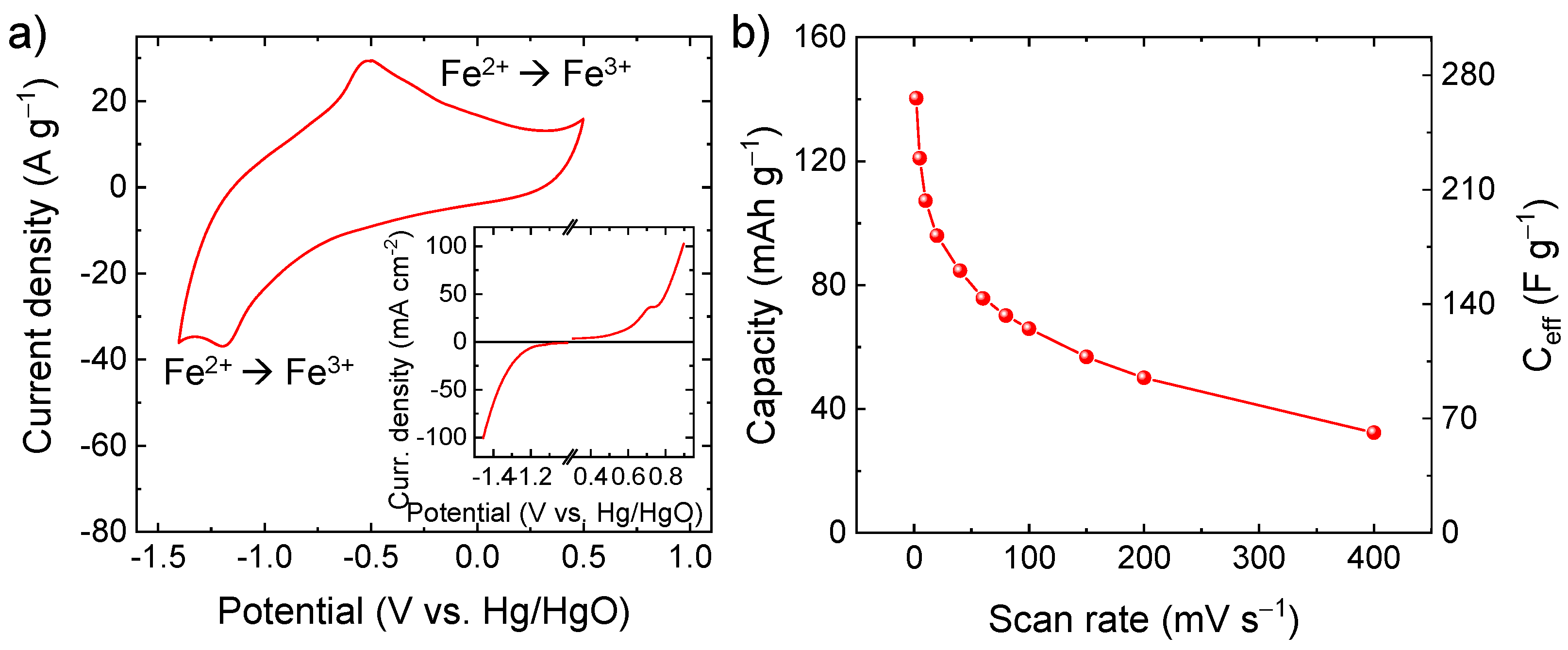
Figure S4 displays the N2 adsorption-desorption isotherm and the BJH pore-size distribution curve of the C-Fe2O3 fibre sample. According to the IUPAC classification [56], the sample exhibits an IV-type isotherm behavior with a H3-type hysteresis loop, revealing the existence of a mesoporous structure with slit-shaped pores. The BET specific surface area, the average pore size, and the total pore volume were calculated to be 6.0 m2 g−1, 3.8 nm and 0.02 cm3 g−1, respectively. The relationship between specific surface area and specific capacity in pseudocapacitive materials is not trivial and is still under debate [14]. Previous work has proven that the crystalline structure could have a larger impact on the specific capacity of electrodes in the presence of pronounced Faradaic processes as compared with the specific surface area [14]. In particular, the capacity of pseudocapacitive materials can correlate with their ionic conductivity, which in turn depends on the crystallographic microstructure [14]. Regarding the case of α-Fe2O3, highly oriented crystals exhibit a lamellar structure [57,58], providing 2D channels for intercalation of ions (e.g., OH, Li+, K+, and Na+), as confirmed in α-Fe2O3-based anodes for batteries [59,60,61,62,63]. In our case, the high-capacity performance of our C-Fe2O3 is mainly attributed to its porous one-dimensional (1D) morphology, resulting in open channels promoting the access of OH to reaction sites where pseudocapacitive reactions take place. As shown by CV analysis (Figure 4a), the electrode based on C-Fe2O3 active material shows clear redox reactions in alkaline aqueous electrolyte (6 M KOH). In particular, the pair of redox peaks located at 1.19 V vs. Hg/HgO and 0.51 V vs. Hg/HgO are ascribed to the reversible redox reaction Fe2+/Fe3+ (i.e., Fe2O3 + OH ⇄ Fe2O3OH + e), in agreement with previous reports [16,64]. As also supported by LSV analysis (inset of Figure 4a), the electrode can operate in a wide potential window (1.9 V) because of its low catalytic activity toward water splitting reaction, i.e., hydrogen evolution reaction (2H2O + 2e → H2 + 2OH, occurring at <−1.2 V vs. Hg/HgO) and oxygen evolution reaction (4OH → O2 + 2H2O + 4e, occurring at >+0.5 V vs. Hg/HgO). In principle, reversible hydrogen electrosorption can also occur at potential <−1.2 V vs. Hg/HgO, competing with the completion of hydrogen evolution reaction and leading to reversible pseudocapacitive contribution [65]. Figure 4b shows the capacity and the corresponding Ceff of the C-Fe2O3-based electrode as a function of the scan rate. At the lowest scan rate of 2 mV s−1, the electrode exhibited a capacity as high as 140.2 mAh g−1 (Ceff = 265.9 F g−1), which was higher or comparable to values reported for α-Fe2O3-based electrodes for SCs in the relevant literature [23,66,67,68,69], excluding electrodes produced using low mass loadings (<1 mg cm−2) or non-practical bulky substrates (e.g., Ni foam and carbon cloth) [41,70,71]. By considering the mass loading of our electrode (1.8 mg cm−2), its areal capacitance is 478.6 mF cm−2, which is superior or comparable to values previously reported in the relevant literature for α-Fe2O3-based electrodes for SCs [22,72]. At the highest scan rate of 400 mV s−1, the electrodes still showed a significant capacity of 32.4 mAh g−1 (Ceff = 61.4 F g−1), proving a satisfactory rate capability for high-power applications. Table S1 reports the comparison between the electrochemical performances of our active materials and those of other Fe2O3-based active materials reported in the literature. On flat substrate (e.g., graphite paper, Ti foil, and glassy carbon), our C-Fe2O3 outperforms most of the previously reported active materials in term of Ceff, competing even with active materials tested on heavy and/or bulky porous substrates (e.g., Ni foam and carbon cloth).
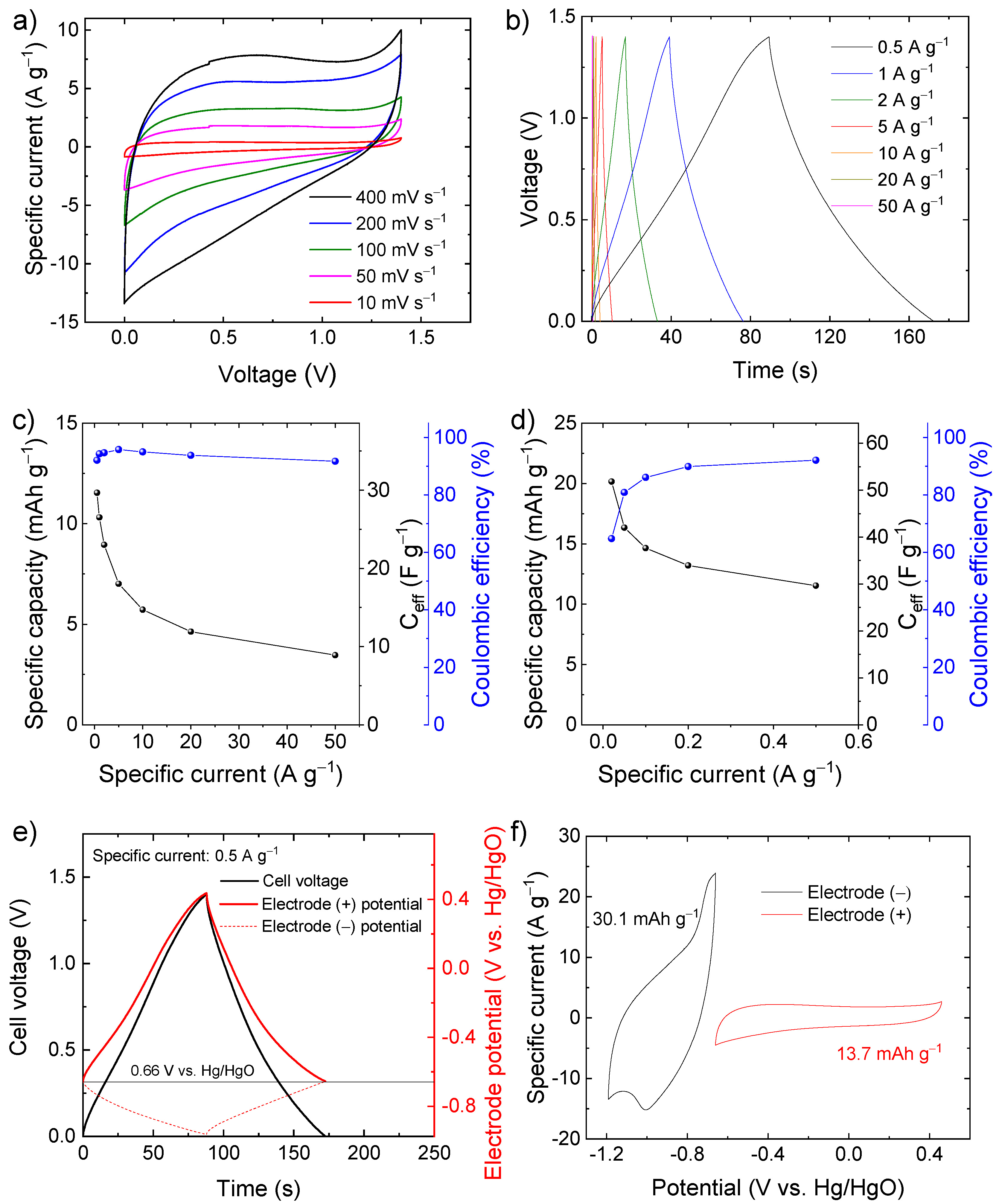
Based on these preliminary results showing high-capacity performance in a wide potential window, the C-Fe2O3 electrodes were used to assemble symmetric SCs. The CV and galvanostatic CD measurements (Figure 5a,b) indicate that the symmetric SCs can operate in a voltage window of 1.4 V with CE higher than 90%, reaching a specific capacity of 11.5 mAh g−1 (Ceff = 29.7 F g−1) at a specific current of 0.5 A g−1 (Figure 5c). At a specific current lower than 0.5 A g−1 (Figure 5d), the symmetric device can reach even a specific capacity of 20.2 mAh g−1 (Ceff = 51.8 F g−1) at 0.02 A g−1, but the CE progressively decay to values lower than 90%. To rationalize the limit of this symmetric SC, the potentials of the positive and negative electrodes were monitored through an auxiliary reference electrode during SC charging and discharging (Figure 5e) at the specific current of 0.5 A g−1. The potential of zero voltage (PZV) of the electrode, i.e., the equipotential of the electrodes when the SC is fully discharged [73], is ca. 0.66 V vs. Hg/HgO. When the SC is charged up to 1.4 V, the positive electrode reaches a maximum potential approaching 0.4 V vs. Hg/HgO, at which oxygen evolution reaction takes place (see Figure 4a), thus, limiting the maximum charging voltage of the cell (see Figure 5a,b). In contrast, the negative electrode reaches a minimum potential of only −0.97 V vs. Hg/HgO, which is well above the potential where irreversible hydrogen evolution reaction occurs (see Figure 4a). These data indicate that the capacities of electrodes are not properly balanced, as further confirmed by CV analysis of the single electrodes (Figure 5f).
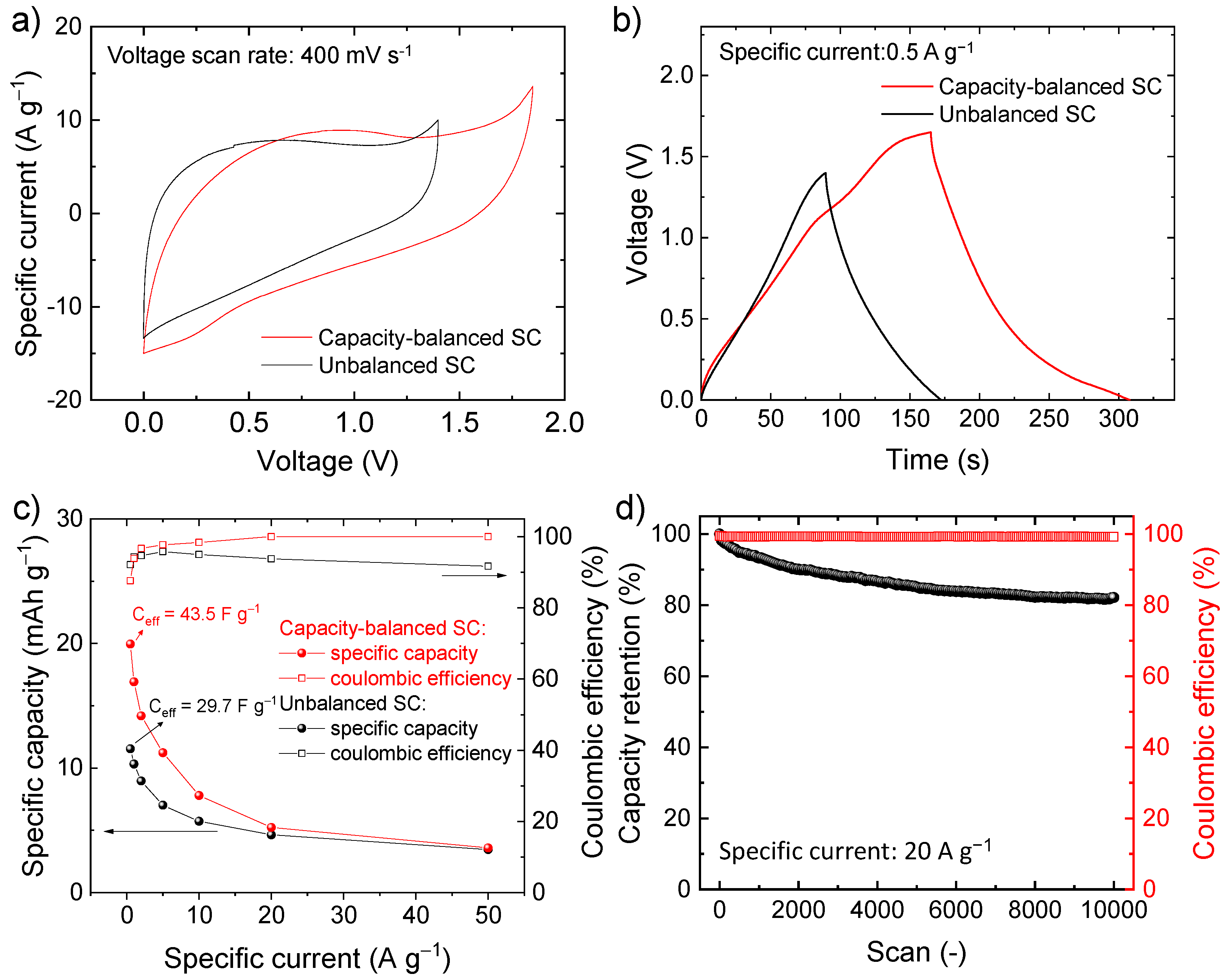
To solve the limitations of the symmetric SC, the capacities of the electrodes were balanced by adjusting the mass loading of the active material according to Equation (7), assuming the specific capacity calculated from the CV curves of the electrodes of the symmetric SC, i.e., 30.1 mAh g−1 for the negative electrode and 13.7 mAh g−1 for the positive electrode (see Figure 5f). Since the electrodes are made of the same chemical composition, the resulting SC is hereafter referred as quasi-symmetric SCs. Figure 6a,b show the comparison between the CV and galvanostatic curves (measured at 400 mV s−1 and 0.5 A g−1, respectively) measured for our capacity-balanced quasi-symmetric SC and the unbalanced device. By balancing the electrode capacities, the voltage window of the SC is extended as compared with the unbalanced devices, significantly improving the specific capacities for the investigated specific currents (Figure 6c), while preserving CE higher than 80%. For example, at 0.5 A g−1, the capacity-balanced SC reached a specific capacity of 20.0 mAh g−1 (Ceff = 43.5 F g−1 and energy density = 9.1 Wh kg−1), while the unbalanced device only exhibited a specific capacity of 11.5 mAh g−1 (Ceff = 29.7 F g−1 and energy density = 4.0 Wh kg−1). Noteworthy, the energy density reached by our capacity-balanced quasi-symmetric SC based on only C-Fe2O3 electrodes is competitive with those of asymmetric SCs recently reported in the relevant literature [74,75,76]. In addition, the stability of the capacity-balanced SC was evaluated over 10,000 galvanostatic CD cycles at 20 A g−1. After 1000 cycles, the device retained more than 90% of the initial capacity. The capacity of the device progressively stabilized over cycling and was still more than 80% at the end of the 10,000 cycles, proving satisfactory electrochemical stability of our C-Fe2O3-based capacity-balanced SC.

4. Conclusions

In summary, in this work, we reported the synthesis of C-Fe2O3 active material by means of electrospinning of Fe salt/polymer composite followed by a thermal treatment (pre-oxidation followed by calcination in Ar atmosphere) of electrospun fibers. The so-produced active material powder can be directly processed in the form of slurry to produce SC electrodes with mass loadings higher than 1 mg cm−2 on practical flat current collectors, eliminating bulky porous substrates that are often used for highly performant electrodes based on nanostructured α-Fe2O3 active material. Thanks to the peculiar 1D morphology and structural/chemical characteristics of the C-Fe2O3 active material made of elongated nanoparticles linearly connected into a worm-like morphology, the resulting electrodes exhibit capacity as high as ~140 mAh g−1 at a scan rate of 2 mV s−1 in 6 M KOH, while showing an optimal rate capability (capacity of 32.4 mAh g−1 at a scan rate of 400 mV s−1). In addition, thanks to the poor catalytic activity of the C-Fe2O3 towards water splitting reactions, the electrodes can operate in a wide potential range (−1.6 V–0.3 V vs. Hg/HgO), enabling the realization of performant and cost-effective quasi-symmetric SCs based on electrodes with the same chemical composition (but different active material mass loadings), achieving energy density approaching to 10 Wh kg−1 in aqueous electrolytes.

Supplementary Materials

The following supporting information can be downloaded at: https://www.mdpi.com/article/10.3390/electrochem3030032/s1, Figure S1: SEM-EDS analysis of C-Fe2O3 active material: (a) SEM image and the corresponding EDS maps for (b) O (K line) and Fe (Kα line), Figure S2: Raman spectrum of C-Fe2O3 in the spectral region of G, D, and 2D peaks of graphitic species (1100–3200 cm−1), Figure S3: Thermogravimetric analysis (TGA) curve measured for C-Fe2O3 in air, Figure S4: N2 adsorption-desorption isotherm and the BJH pore-size distribution curve of the C-Fe2O3, Table S1: Comparison between the electrochemical performances of our C-Fe2O3 and other Fe2O3-based active materials reported in relevant literature. The table is subdivided in different categories (indicated by different colors), depending on the substrate used for the electrochemical characterization of the active material.

Author Contributions

Conceptualization, M.N. and S.B.; Data curation, M.N., V.G., M.I.Z., A.B., M.S., H.B., M.E., L.P., R.C., S.L., J.-K.P., R.B. and L.G.; Formal analysis, S.B., V.G., M.I.Z., A.B., M.S., H.B., M.E., L.P., R.C., S.L., J.-K.P., R.B. and L.G.; Funding acquisition, V.P. and F.B.; Investigation, M.N., S.B. and F.B.; Methodology, S.B., M.E., L.P., R.C. and S.L.; Resources, V.P. and F.B.; Supervision, S.B., V.P. and F.B.; Writing—original draft, S.B.; Writing—review and editing, M.N., V.G., M.I.Z., A.B. amd M.S.; Safarpour, H.B., M.E., L.P., R.C., J.-K.P., V.P. and F.B. All authors have read and agreed to the published version of the manuscript.

Funding

This project has received funding from the European Union’s Horizon 2020 research and innovation program under the Marie Skłodowska-Curie grant agreement no. 813036, the European Union’s Horizon 2020 research and innovation program under grant agreement no. 881603-GrapheneCore3, the European Union’s SENSIBAT project under grant agreement no. 957273. We thank the Electron Microscopy and Material Characterization facilities –Istituto Italiano di Tecnologia– for support in SEM/TEM and XRD/BET data acquisition, respectively.

Institutional Review Board Statement

Not applicable.

Informed Consent Statement

Not applicable.

Data Availability Statement

Not applicable.

Conflicts of Interest

The authors declare no conflict of interest.

References

  1. Raza, W.; Ali, F.; Raza, N.; Luo, Y.; Kim, K.H.; Yang, J.; Kumar, S.; Mehmood, A.; Kwon, E.E. Recent Advancements in Supercapacitor Technology. Nano Energy 2018, 52, 441–473. [Google Scholar] [CrossRef]
  2. Bobba, S.; Carrara, S.; Huisman, J.; Mathieux, F.; Pavel, C. Critical Raw Materials for Strategic Technologies and Sectors in the EU—A Foresight Study; European Commission: Brussels Belgium, 2020; ISBN 9789276153375. [Google Scholar]
  3. Huang, S.; Zhu, X.; Sarkar, S.; Zhao, Y. Challenges and Opportunities for Supercapacitors. APL Mater. 2019, 7, 100901. [Google Scholar] [CrossRef]
  4. Zhu, X. Recent Advances of Transition Metal Oxides and Chalcogenides in Pseudo-Capacitors and Hybrid Capacitors: A Review of Structures, Synthetic Strategies, and Mechanism Studies. J. Energy Storage 2022, 49, 104148. [Google Scholar] [CrossRef]
  5. Liu, R.; Zhou, A.; Zhang, X.; Mu, J.; Che, H.; Wang, Y.; Wang, T.T.; Zhang, Z.; Kou, Z. Fundamentals, Advances and Challenges of Transition Metal Compounds-Based Supercapacitors. Chem. Eng. J. 2021, 412, 128611. [Google Scholar] [CrossRef]
  6. Bellani, S.; Najafi, L.; Tullii, G.; Ansaldo, A.; Oropesa-Nuñez, R.; Prato, M.; Colombo, M.; Antognazza, M.R.; Bonaccorso, F. ITO Nanoparticles Break Optical Transparency/High-Areal Capacitance Trade-off for Advanced Aqueous Supercapacitors. J. Mater. Chem. A 2017, 5, 25177–25186. [Google Scholar] [CrossRef]
  7. Fu, L.; Qu, Q.; Holze, R.; Kondratiev, V.V.; Wu, Y. Composites of Metal Oxides and Intrinsically Conducting Polymers as Supercapacitor Electrode Materials: The Best of Both Worlds? J. Mater. Chem. A 2019, 7, 14937–14970. [Google Scholar] [CrossRef]
  8. Naskar, P.; Maiti, A.; Chakraborty, P.; Kundu, D.; Biswas, B.; Banerjee, A. Chemical Supercapacitors: A Review Focusing on Metallic Compounds and Conducting Polymers. J. Mater. Chem. A 2021, 9, 1970–2017. [Google Scholar] [CrossRef]
  9. Fleischmann, S.; Mitchell, J.B.; Wang, R.; Zhan, C.; Jiang, D.E.; Presser, V.; Augustyn, V. Pseudocapacitance: From Fundamental Understanding to High Power Energy Storage Materials. Chem. Rev. 2020, 120, 6738–6782. [Google Scholar] [CrossRef]
  10. Choi, C.; Ashby, D.S.; Butts, D.M.; DeBlock, R.H.; Wei, Q.; Lau, J.; Dunn, B. Achieving High Energy Density and High Power Density with Pseudocapacitive Materials. Nat. Rev. Mater. 2020, 5, 5–19. [Google Scholar] [CrossRef]
  11. Zhao, J.; Burke, A.F. Electrochemical Capacitors: Materials, Technologies and Performance. Energy Storage Mater. 2021, 36, 31–55. [Google Scholar] [CrossRef]
  12. Liu, J.; Wang, J.; Xu, C.; Jiang, H.; Li, C.; Zhang, L.; Lin, J.; Shen, Z.X. Advanced Energy Storage Devices: Basic Principles, Analytical Methods, and Rational Materials Design. Adv. Sci. 2018, 5, 1700322. [Google Scholar] [CrossRef] [PubMed]
  13. Fleischmann, S.; Zhang, Y.; Wang, X.; Cummings, P.T.; Wu, J.; Simon, P.; Gogotsi, Y.; Presser, V.; Augustyn, V. Continuous Transition from Double-Layer to Faradaic Charge Storage in Confined Electrolytes. Nat. Energy 2022, 7, 222–228. [Google Scholar] [CrossRef]
  14. Wei, W.; Cui, X.; Chen, W.; Ivey, D.G. Manganese Oxide -Based Materials as Electrochemical Supercapacitor Electrodes. Chem. Soc. Rev. 2011, 40, 1697–1721. [Google Scholar] [CrossRef] [PubMed]
  15. An, C.; Zhang, Y.; Guo, H.; Wang, Y. Metal Oxide-Based Supercapacitors: Progress and Prospectives. Nanoscale Adv. 2019, 1, 4644–4658. [Google Scholar] [CrossRef]
  16. Nithya, V.D.; Arul, N.S. Review on α-Fe2O3 Based Negative Electrode for High Performance Supercapacitors. J. Power Sources 2016, 327, 297–318. [Google Scholar] [CrossRef]
  17. Gogotsi, Y.; Simon, P. True Performance Metrics in Electrochemical Energy Storage. Science 2012, 335, 167. [Google Scholar] [CrossRef]
  18. Guan, C.; Liu, J.; Wang, Y.; Mao, L.; Fan, Z.; Shen, Z.; Zhang, H.; Wang, J. Iron Oxide-Decorated Carbon for Supercapacitor Anodes with Ultrahigh Energy Density and Outstanding Cycling Stability. ACS Nano 2015, 9, 5198–5207. [Google Scholar] [CrossRef]
  19. Liu, Y.; Jiang, S.P.; Shao, Z. Intercalation Pseudocapacitance in Electrochemical Energy Storage: Recent Advances in Fundamental Understanding and Materials Development. Mater. Today Adv. 2020, 7, 100072. [Google Scholar] [CrossRef]
  20. Li, J.; Chen, D.; Wu, Q. α-Fe2O3 Based Carbon Composite as Pure Negative Electrode for Application as Supercapacitor. Eur. J. Inorg. Chem. 2019, 10, 1301–1312. [Google Scholar] [CrossRef]
  21. Zeng, Y.; Yu, M.; Meng, Y.; Fang, P.; Lu, X.; Tong, Y. Iron-Based Supercapacitor Electrodes: Advances and Challenges. Adv. Energy Mater. 2016, 6, 1601053. [Google Scholar] [CrossRef]
  22. Lu, X.; Zeng, Y.; Yu, M.; Zhai, T.; Liang, C.; Xie, S.; Balogun, M.-S.; Tong, Y. Oxygen-Deficient Hematite Nanorods as High-Performance and Novel Negative Electrodes for Flexible Asymmetric Supercapacitors. Adv. Mater. 2014, 26, 3148–3155. [Google Scholar] [CrossRef] [PubMed]
  23. Lee, K.K.; Deng, S.; Fan, H.M.; Mhaisalkar, S.; Tan, H.R.; Tok, E.S.; Loh, K.P.; Chin, W.S.; Sow, C.H. α-Fe2O3 Nanotubes-Reduced Graphene Oxide Composites as Synergistic Electrochemical Capacitor Materials. Nanoscale 2012, 4, 2958–2961. [Google Scholar] [CrossRef]
  24. Del Rio Castillo, A.E.; Pellegrini, V.; Ansaldo, A.; Ricciardella, F.; Sun, H.; Marasco, L.; Buha, J.; Dang, Z.; Gagliani, L.; Lago, E.; et al. High-Yield Production of 2D Crystals by Wet-Jet Milling. Mater. Horizons 2018, 5, 890–904. [Google Scholar] [CrossRef]
  25. Bellani, S.; Petroni, E.; Del Rio Castillo, A.E.; Curreli, N.; Martín-García, B.; Oropesa-Nuñez, R.; Prato, M.; Bonaccorso, F. Scalable Production of Graphene Inks via Wet-Jet Milling Exfoliation for Screen-Printed Micro-Supercapacitors. Adv. Funct. Mater. 2019, 29, 1807659. [Google Scholar] [CrossRef]
  26. Bellani, S.; Martín-Garciá, B.; Oropesa-Nuñez, R.; Romano, V.; Najafi, L.; Demirci, C.; Prato, M.; Del Rio Castillo, A.E.; Marasco, L.; Mantero, E.; et al. “Ion Sliding” on Graphene: A Novel Concept to Boost Supercapacitor Performance. Nanoscale Horizons 2019, 4, 1077–1091. [Google Scholar] [CrossRef]
  27. Garakani, M.A.; Bellani, S.; Pellegrini, V.; Oropesa-Nuñez, R.; Castillo, A.E.D.R.; Abouali, S.; Najafi, L.; Martín-García, B.; Ansaldo, A.; Bondavalli, P.; et al. Scalable Spray-Coated Graphene-Based Electrodes for High-Power Electrochemical Double-Layer Capacitors Operating over a Wide Range of Temperature. Energy Storage Mater. 2021, 34, 1–11. [Google Scholar] [CrossRef]
  28. Chodankar, N.R.; Pham, H.D.; Nanjundan, A.K.; Fernando, J.F.S.; Jayaramulu, K.; Golberg, D.; Han, Y.K.; Dubal, D.P. True Meaning of Pseudocapacitors and Their Performance Metrics: Asymmetric versus Hybrid Supercapacitors. Small 2020, 16, 2002806. [Google Scholar] [CrossRef] [PubMed]
  29. Noori, A.; El-Kady, M.F.; Rahmanifar, M.S.; Kaner, R.B.; Mousavi, M.F. Towards Establishing Standard Performance Metrics for Batteries, Supercapacitors and Beyond. Chem. Soc. Rev. 2019, 48, 1272–1341. [Google Scholar] [CrossRef]
  30. Ansaldo, A.; Bondavalli, P.; Bellani, S.; Del Rio Castillo, A.E.; Prato, M.; Pellegrini, V.; Pognon, G.; Bonaccorso, F. High-Power Graphene–Carbon Nanotube Hybrid Supercapacitors. ChemNanoMat 2017, 3, 436–446. [Google Scholar] [CrossRef]
  31. Laheäär, A.; Przygocki, P.; Abbas, Q.; Béguin, F. Appropriate Methods for Evaluating the Efficiency and Capacitive Behavior of Different Types of Supercapacitors. Electrochem. Commun. 2015, 60, 21–25. [Google Scholar] [CrossRef]
  32. Xue, J.; Wu, T.; Dai, Y.; Xia, Y. Electrospinning and Electrospun Nanofibers: Methods, Materials, and Applications. Chem. Rev. 2019, 119, 5298–5415. [Google Scholar] [CrossRef] [PubMed]
  33. Wu, M.; Wang, Q.; Li, K.; Wu, Y.; Liu, H. Optimization of Stabilization Conditions for Electrospun Polyacrylonitrile Nanofibers. Polym. Degrad. Stab. 2012, 97, 1511–1519. [Google Scholar] [CrossRef]
  34. Xu, T.; Nguyen, A.; Rosas, N.; Flores, I.; Chen, C.; Gan, J.B.; Hamdan, A.S.; Gan, Y.X. Effect of Pyrolysis Temperature on the Electrical Property and Photosensitivity of a PAN-PMMA Derived Carbon Fiber. ChemEngineering 2019, 3, 86. [Google Scholar] [CrossRef]
  35. Gao, Z.; Kaneko, T.; Hou, D.; Nakada, M. Kinetics of Thermal Degradation of Poly(Methyl Methacrylate) Studied with the Assistance of the Fractional Conversion at the Maximum Reaction Rate. Polym. Degrad. Stab. 2004, 84, 399–403. [Google Scholar] [CrossRef]
  36. Holland, B.J.; Hay, J.N. The Kinetics and Mechanisms of the Thermal Degradation of Poly(Methyl Methacrylate) Studied by Thermal Analysis-Fourier Transform Infrared Spectroscopy. Polymer 2001, 42, 4825–4835. [Google Scholar] [CrossRef]
  37. Peterson, J.D.; Vyazovkin, S.; Wight, C.A. Kinetic Study of Stabilizing Effect of Oxygen on Thermal Degradation of Poly(Methyl Methacrylate). J. Phys. Chem. B 1999, 103, 8087–8092. [Google Scholar] [CrossRef]
  38. Peng, Y.T.; Lo, C.T. Electrospun Porous Carbon Nanofibers as Lithium Ion Battery Anodes. J. Solid State Electrochem. 2015, 19, 3401–3410. [Google Scholar] [CrossRef]
  39. Mohapatra, P.; Shaw, S.; Mendivelso-Perez, D.; Bobbitt, J.M.; Silva, T.F.; Naab, F.; Yuan, B.; Tian, X.; Smith, E.A.; Cademartiri, L. Calcination Does Not Remove All Carbon from Colloidal Nanocrystal Assemblies. Nat. Commun. 2017, 8, 2038. [Google Scholar] [CrossRef]
  40. Lemine, O.M. Microstructural Characterisation of α-Fe2O3 Nanoparticles Using, XRD Line Profiles Analysis, FE-SEM and FT-IR. Superlattices Microstruct. 2009, 45, 576–582. [Google Scholar] [CrossRef]
  41. Chen, L.; Liu, D.; Yang, P. Preparation of α-Fe2O3/RGO Composites toward Supercapacitor Applications. RSC Adv. 2019, 9, 12793–12800. [Google Scholar] [CrossRef]
  42. De Faria, D.L.A.; Venâncio Silva, S.; De Oliveira, M.T. Raman Microspectroscopy of Some Iron Oxides and Oxyhydroxides. J. Raman Spectrosc. 1997, 28, 873–878. [Google Scholar] [CrossRef]
  43. Emons, T.T.; Li, J.; Nazar, L.F. Synthesis and Characterization of Mesoporous Indium Tin Oxide Possessing an Electronically Conductive Framework. J. Am. Chem. Soc. 2002, 124, 8516–8517. [Google Scholar] [CrossRef] [PubMed]
  44. Bersani, D.; Lottici, P.P.; Montenero, A. Micro-Raman Investigation of Iron Oxide Films and Powders Produced by Sol-Gel Syntheses. J. Raman Spectrosc. 1999, 30, 355–360. [Google Scholar] [CrossRef]
  45. Cao, H.; Wang, G.; Zhang, L.; Liang, Y.; Zhang, S.; Zhang, X. Shape and Magnetic Properties of Single-Crystalline Hematite (α-Fe2O3) Nanocrystals. ChemPhysChem 2006, 7, 1897–1901. [Google Scholar] [CrossRef]
  46. Shim, S.H.; Duffy, T.S. Raman Spectroscopy of Fe2O3 to 62 GPa. Am. Mineral. 2002, 87, 318–326. [Google Scholar] [CrossRef]
  47. Yamashita, T.; Hayes, P. Analysis of XPS Spectra of Fe2+ and Fe3+ Ions in Oxide Materials. Appl. Surf. Sci. 2008, 254, 2441–2449. [Google Scholar] [CrossRef]
  48. López-Sánchez, J.; Del Campo, A.; Román-Sánchez, S.; de la Fuente, Ó.R.; Carmona, N.; Serrano, A. Large Two-Magnon Raman Hysteresis Observed in a Magnetically Uncompensated Hematite Coating across the Morin Transition. Coatings 2022, 12, 540. [Google Scholar] [CrossRef]
  49. Owens, F.J.; Orosz, J. Effect of Nanosizing on Lattice and Magnon Modes of Hematite. Solid State Commun. 2006, 138, 95–98. [Google Scholar] [CrossRef]
  50. Farahmandjou, M.; Soflaee, F. Low Temperature Synthesis of α-Fe2O3 Nano-Rods Using Simple Chemical. J. Nanostruct. 2014, 4, 413–418. [Google Scholar]
  51. Hao, C.; Shen, Y.; Wang, Z.; Wang, X.; Feng, F.; Ge, C.; Zhao, Y.; Wang, K. Preparation and Characterization of Fe2O3 Nanoparticles by Solid-Phase Method and Its Hydrogen Persoxide Sensing Properties. ACS Sustain. Chem. Eng. 2016, 4, 1069–1077. [Google Scholar] [CrossRef]
  52. Fard, G.C.; Mirjalili, M.; Najafi, F. Preparation of Nano-Cellulose/ α-Fe2O3 Hybrid Nanofiber for the Cationic Dyes Removal: Optimization Characterization, Kinetic, Isotherm and Error Analysis. Bulg. Chem. Commun. 2018, 50, 251–261. [Google Scholar]
  53. Han, T.; Wei, Y.; Jin, X.; Jiu, H.; Zhang, L.; Sun, Y.; Tian, J.; Shang, R.; Hang, D.; Zhao, R. Hydrothermal Self-Assembly of α-Fe2O3 Nanorings@graphene Aerogel Composites for Enhanced Li Storage Performance. J. Mater. Sci. 2019, 54, 7119–7130. [Google Scholar] [CrossRef]
  54. Mills, P.; Sullivan, J.L. A Study of the Core Level Electrons in Iron and Its Three Oxides by Means of X-Ray Photoelectron Spectroscopy. J. Phys. D Appl. Phys. 1983, 16, 723. [Google Scholar] [CrossRef]
  55. Mansour, A.N.; Brizzolara, R.A. Characterization of the Surface of γ-Fe2O3 Powder by XPS. Surf. Sci. Spectra 2021, 4, 351. [Google Scholar] [CrossRef]
  56. Thommes, M.; Kaneko, K.; Neimark, A.V.; Olivier, J.P.; Rodriguez-Reinoso, F.; Rouquerol, J.; Sing, K.S.W. Physisorption of Gases, with Special Reference to the Evaluation of Surface Area and Pore Size Distribution (IUPAC Technical Report). Pure Appl. Chem. 2015, 87, 1051–1069. [Google Scholar] [CrossRef]
  57. Puthirath Balan, A.; Radhakrishnan, S.; Woellner, C.F.; Sinha, S.K.; Deng, L.; Reyes, C.D.L.; Rao, B.M.; Paulose, M.; Neupane, R.; Apte, A.; et al. Exfoliation of a Non-van Der Waals Material from Iron Ore Hematite. Nat. Nanotechnol. 2018, 13, 602–609. [Google Scholar] [CrossRef]
  58. Mohapatra, J.; Ramos, A.; Elkins, J.; Beatty, J.; Xing, M.; Singh, D.; La Plante, E.C.; Ping Liu, J. Ferromagnetism in 2D α-Fe2O3 Nanosheets. Appl. Phys. Lett. 2021, 118, 183102. [Google Scholar] [CrossRef]
  59. Tao, Y.; Ding, C.; Tan, D.; Yu, F.; Wang, F. Aqueous Dual-Ion Battery Based on a Hematite Anode with Exposed {1 0 4} Facets. ChemSusChem 2018, 11, 4269–4274. [Google Scholar] [CrossRef]
  60. Kim, H.S.; Piao, Y.; Kang, S.H.; Hyeon, T.; Sung, Y.E. Uniform Hematite Nanocapsules Based on an Anode Material for Lithium Ion Batteries. Electrochem. Commun. 2010, 12, 382–385. [Google Scholar] [CrossRef]
  61. Modafferi, V.; Triolo, C.; Fiore, M.; Palella, A.; Spadaro, L.; Pianta, N.; Ruffo, R.; Patanè, S.; Santangelo, S.; Musolino, M.G. Effect of Hematite Doping with Aliovalent Impurities on the Electrochemical Performance of α-Fe2O3@rGO-Based Anodes in Sodium-Ion Batteries. Nanomaterials 2020, 10, 1588. [Google Scholar] [CrossRef]
  62. Xia, G.; Gao, Q.; Sun, D.; Yu, X. Porous Carbon Nanofibers Encapsulated with Peapod-Like Hematite Nanoparticles for High-Rate and Long-Life Battery Anodes. Small 2017, 13, 1701561. [Google Scholar] [CrossRef] [PubMed]
  63. Ma, J.; Li, Y.; Wei, X.; Liu, C. Construction of Conductive Network in Hematite for Lithium, Sodium and Potassium Storage. J. Alloys Compd. 2021, 889, 161766. [Google Scholar] [CrossRef]
  64. Zhu, M.; Wang, Y.; Meng, D.; Qin, X.; Diao, G. Hydrothermal Synthesis of Hematite Nanoparticles and Their Electrochemical Properties. J. Phys. Chem. C 2012, 116, 16276–16285. [Google Scholar] [CrossRef]
  65. Chun, S.E.; Whitacre, J.F. Investigating the Role of Electrolyte Acidity on Hydrogen Uptake in Mesoporous Activated Carbons. J. Power Sources 2013, 242, 137–140. [Google Scholar] [CrossRef]
  66. Binitha, G.; Soumya, M.S.; Madhavan, A.A.; Praveen, P.; Balakrishnan, A.; Subramanian, K.R.V.; Reddy, M.V.; Nair, S.V.; Nair, A.S.; Sivakumar, N. Electrospun α-Fe2O3 Nanostructures for Supercapacitor Applications. J. Mater. Chem. A 2013, 1, 11698–11704. [Google Scholar] [CrossRef]
  67. Kulal, P.M.; Dubal, D.P.; Lokhande, C.D.; Fulari, V.J. Chemical Synthesis of Fe2O3 Thin Films for Supercapacitor Application. J. Alloys Compd. 2011, 509, 2567–2571. [Google Scholar] [CrossRef]
  68. Xie, K.; Li, J.; Lai, Y.; Lu, W.; Zhang, Z.; Liu, Y.; Zhou, L.; Huang, H. Highly Ordered Iron Oxide Nanotube Arrays as Electrodes for Electrochemical Energy Storage. Electrochem. Commun. 2011, 13, 657–660. [Google Scholar] [CrossRef]
  69. Sethuraman, B.; Purushothaman, K.K.; Muralidharan, G. Synthesis of Mesh-like Fe2O3/C Nanocomposite via Greener Route for High Performance Supercapacitors. RSC Adv. 2013, 4, 4631–4637. [Google Scholar] [CrossRef]
  70. Owusu, K.A.; Qu, L.; Li, J.; Wang, Z.; Zhao, K.; Yang, C.; Hercule, K.M.; Lin, C.; Shi, C.; Wei, Q.; et al. Low-Crystalline Iron Oxide Hydroxide Nanoparticle Anode for High-Performance Supercapacitors. Nat. Commun. 2017, 8, 14264. [Google Scholar] [CrossRef]
  71. Tang, Q.; Wang, W.; Wang, G. The Perfect Matching between the Low-Cost Fe2O3 Nanowire Anode and the NiO Nanoflake Cathode Significantly Enhances the Energy Density of Asymmetric Supercapacitors. J. Mater. Chem. A 2015, 3, 6662–6670. [Google Scholar] [CrossRef]
  72. Lu, X.F.; Chen, X.Y.; Zhou, W.; Tong, Y.X.; Li, G.R. α-Fe2O3@PANI Core-Shell Nanowire Arrays as Negative Electrodes for Asymmetric Supercapacitors. ACS Appl. Mater. Interfaces 2015, 7, 14843–14850. [Google Scholar] [CrossRef]
  73. Dai, Z.; Peng, C.; Chae, J.H.; Ng, K.C.; Chen, G.Z. Cell Voltage versus Electrode Potential Range in Aqueous Supercapacitors. Sci. Rep. 2015, 5, 9854. [Google Scholar] [CrossRef] [PubMed]
  74. He, Y.; Chen, W.; Gao, C.; Zhou, J.; Li, X.; Xie, E. An Overview of Carbon Materials for Flexible Electrochemical Capacitors. Nanoscale 2013, 5, 8799–8820. [Google Scholar] [CrossRef]
  75. Zhou, C.; Zhang, Y.; Li, Y.; Liu, J. Construction of High-Capacitance 3D CoO@Polypyrrole Nanowire Array Electrode for Aqueous Asymmetric Supercapacitor. Nano Lett. 2013, 13, 2078–2085. [Google Scholar] [CrossRef] [PubMed]
  76. Shanmugavani, A.; Selvan, R.K. Microwave Assisted Reflux Synthesis of NiCo2O4/NiO Composite: Fabrication of High Performance Asymmetric Supercapacitor with Fe2O3. Electrochim. Acta 2016, 189, 283–294. [Google Scholar] [CrossRef]
Scheme 1. Synthesis of C-Fe2O3 active material by: (1) electrospinning of PAN/PMMA/C4H14FeO8 solution in DMF followed by; (2) pre-oxidation; and (3) calcination/carbonization steps.
Electrochem 03 00032 sch001
Figure 1. (a) BF-TEM image and (b) SEM image of the as-synthesized powder of C-Fe2O3 active material. STEM-EDS analysis of the C-Fe2O3 active material: (c) High-angle annular dark-field (HAADF)-STEM image and the corresponding EDS maps for (d) Fe (Kα), (e) O (K), and (f) C (K). In panel (f), the C map is overlapped with the HAADF-STEM image, to emphasize the region on which the quantitative elemental analysis has been performed (defined by the line linking the yellow dots), suspended on a hole in the carbon film.
Electrochem 03 00032 g001
Figure 2. (a) XRD pattern; (b) Raman and (c) FT-IR spectra of the as-synthesized C-Fe2O3 active material. In panel (a), the reference XRD pattern of α-Fe2O3 (ICSD structure-22505) is also shown in red bars.
Electrochem 03 00032 g002
Figure 3. (a) Wide scan; (b) Fe 2p; (c) O 1s XPS spectra, of C-Fe2O3.
Electrochem 03 00032 g003
Figure 4. (a) CV curve of the C-Fe2O3-based electrode in 6 M KOH (potential scan rate = 100 mV s−1). The inset shows the LSV analysis of the electrode, indicating the onset potential of irreversible water splitting reaction (potential scan rate = 2 mV s−1); (b) capacity and Ceff of the C-Fe2O3-based electrode as a function of the potential scan rate.
Electrochem 03 00032 g004
Figure 5. (a) CV curves of symmetric SC-based C-Fe2O3 electrodes measured at different voltage scan rates (from 10 to 400 mV s−1) in 6 M KOH; (b) galvanostatic CD curves of the same SC measured at different specific currents (from 0.5 to 50 A g−1); (c) capacity, Ceff, and CE of the symmetric SC as a function of the specific current, ranging from 0.5 to 50 A g−1; (d) capacity, Ceff, and CE of the symmetric SC measured at low specific currents (from 0.02 to 0.5 A g−1); (e) galvanostatic CD curve of the symmetric SC measured at specific current of 0.5 A g−1 and the corresponding galvanostatic CD curves measured for the negative and positive electrodes (named electrode (−) and electrode (+), respectively) in a three-electrode cell configuration by means of a reference electrode; (f) CV curves measured for our positive and negative electrodes in a three-electrode cell configuration. The maximum and minimum potential vertexes of the negative and positive electrodes, respectively, were set nearby the PZV of the electrodes in the symmetric SC (between 0.6 and 0.7 V vs. Hg/HgO).
Electrochem 03 00032 g005
Figure 6. (a) Comparison between the CV curves measured for unbalanced SC and capacity balanced SC-based on C-Fe2O3 electrodes (voltage scan rate = 400 mV s−1); (b) comparison between the galvanostatic CD curves measured for unbalanced SC and capacity balanced SC based on C-Fe2O3 electrodes (specific current = 0.5 A g−1); (c) capacity and CE of the quasi-symmetric SC as a function of the specific current; (d) capacity retention and CE over 10,000 galvanostatic CD cycles (specific current = 20 A g−1).
Electrochem 03 00032 g006
Publisher’s Note: MDPI stays neutral with regard to jurisdictional claims in published maps and institutional affiliations.