Article

High-Rate Performance of a Designed Si Nanoparticle–Graphite Nanosheet Composite as the Anode for Lithium-Ion Batteries

by
Vahide Ghanooni Ahmadabadi
*,
Md Mokhlesur Rahman
and
Ying Chen
Institute for Frontier Materials, Deakin University, Waurn Ponds, Geelong, VIC 3216, Australia
*
Author to whom correspondence should be addressed.
Electrochem 2024, 5(2), 133-145; https://doi.org/10.3390/electrochem5020009
Submission received: 5 January 2024 / Revised: 27 February 2024 / Accepted: 15 March 2024 / Published: 9 April 2024
(This article belongs to the Collection Feature Papers in Electrochemistry)

Abstract

:
A silicon nanoparticle–graphite nanosheet composite was prepared via a facile ball milling process for use as the anode for high-rate lithium-ion batteries. The size effect of Si nanoparticles on the structure and on the lithium-ion battery performance of the composite is evaluated. SEM and TEM analyses show a structural alteration of the composites from Si nanoparticle-surrounded graphite nanosheets to Si nanoparticle-embedded graphite nanosheets by decreasing the size of Si nanoparticles from 250 nm to 40 nm. The composites with finer Si nanoparticles provide an effective nanostructure containing encapsulated Si and free space. This structure facilitates the indirect exposure of Si to electrolyte and Si expansion during cycling, which leads to a stable solid–electrolyte interphase and elevated conductivity. An enhanced rate capability was obtained for the 40 nm Si nanoparticle–graphite nanosheet composite, delivering a specific capacity of 276 mAh g−1 at a current density of 1 C after 1000 cycles and a rate capacity of 205 mAh g−1 at 8 C.

1. Introduction

Lithium-ion batteries (LIBs), with high power and high energy density along with high charge and discharge rates, can fulfill the desire to substitute internal combustion engine (ICE) cars with green vehicles, such as hybrid electric vehicles (HEVs), plug-in HEVs, and electric vehicles (EVs), and to store wind and solar energy to transition from the depleting and CO2 emission sources of fossil fuels [1]. To achieve high-performance LIBs, the development of electrode materials, especially high-rate anode materials, with low-cost and scalable production processes, is necessary [2,3].
To enhance the rate capability of the electrodes, active material design with the aim of decreasing the diffusion pathways and increasing the conductivity of the materials is required, which will provide fast Li+ ion and electron transport within the materials. Strategies of nanostructuring the active material and adding conductive materials can speed up Li+ ion and electron movement inside the electrode, respectively [4].
Among anode materials, silicon has attracted interest due to its high theoretical capacity of 4200 mAh g−1, low discharge voltage vs. Li/Li+, and natural abundance. However, its main issue of high volume change (~420%) upon lithiation/de-lithiation causes rapid capacity fading due to structural destruction and unstable SEI (solid–electrolyte interphase) layer [5]. Many efforts have been devoted to addressing these issues through the design of nanoscale Si anodes, e.g., nanoparticles, nanosheets, nanotubes, nanowires, porous nanostructures, and their particular hybrid structures [6,7,8,9,10,11,12,13]. Nanostructured Si is capable of relieving the created stress–strain during lithiation/de-lithiation and can prevent fracture, as was revealed for Si nanoparticles below ~150 nm [2]. Nanostructured Si can also provide short diffusion paths for traveling Li+ ions and improve the rate capability of the electrode [14]. Furthermore, the fabrication of Si nanostructured composites with carbon materials is an effective strategy to solve the issue of the slow ion/electron transport rate in silicon along with increasing the conductivity and rate capacity of the anode [15]. Si-C composites with various structures have been developed; however, the structures in which Si is encapsulated inside the carbon material with space around Si, such as yolk–shell structures, represent the best performance due to the compensation of the volume change and formation of a stable SEI layer on carbon materials [16]. Graphite has been a good candidate for the preparation of Si-C composites because of its low volume change during lithiation (only 10%), high electronic conductivity, and natural abundance [17,18,19,20,21,22]. Si–graphite hybrids can also compensate for the low theoretical capacity of graphite (372 mAh g−1).
As continued progress on Si-C composite anodes, Yim et al. [19] produced a composite of Si/carbon/graphite by a combined chemical–thermal process which delivers a specific capacity of 712 mAh g−1 after 50 cycles at a current density of 130 mA g−1. A silicon/carbon/natural graphite composite was also reported by Wang et al. [20] prepared by a chemical–mechanical–thermal procedure. This composite delivers a specific capacity of ~471 mAh g−1 after 100 cycles at a current density of 100 mA g−1. M. Cabello et al. prepared a silicon–graphite anode through a wet ball milling method, which represents a capacity of ~800 mAh g−1 at 5 A g−1 [21].
Along the way towards the development of the Si–graphite composites for practical applications, the preparation procedures should be improved to simpler, cost-effective, and scalable methods. There is little work addressing the simple composite of Si–graphite with no chemical additives/embedded elements/coating/heat treatment in the synthesis process. Furthermore, there is still plenty of room to study the rate capability of the Si–graphite composites for high-rate lithium-ion batteries. It is therefore needed to produce high-rate Si–graphite composite anodes via a scalable production method.
In this study, a Si–graphite nanocomposite was designed and prepared via a most facile and scalable ball milling process in which the starting materials of graphite nanosheets and Si nanoparticles were also prepared by the ball milling technique. Graphite nanosheets and Si nanoparticles were used with the aim of developing a composite structure containing (i) nanosized Si particles for buffering the internal stress due to volume change, (ii) well-encapsulated Si nanoparticles in a graphite matrix to provide the indirect contact of Si with the electrolyte, (iii) enough free spaces for compensating Si expansion during lithiation, and (iv) a nanoscale structure for increasing the transfer rate of Li+ and electrons. Such an electrode architecture is expected to enhance the cyclability and rate capability of the Si–graphite composite by providing a stable SEI layer and improved conductivity. The preparation of Si–graphite composites along with the size effect of Si nanoparticles on the composite structure and LIB performance are discussed.

2. Materials and Methods

2.1. Preparation of Starting Materials

The required starting materials for the Si–graphite nanocomposites were produced using the ball milling machine of the Fritsch PULVERISETTE7 premium line with 80 mL vials and 1.25–1.6 mm zirconia microbeads. Firstly, commercial graphite powder (particle size < 20 μm, Sigma-Aldrich, Sofia, Bulgaria) was ball-milled for 2 h to exfoliate graphite into graphite nanosheets, which is explained elsewhere [23]. In the second stage, Si nanoparticles were produced in two different particle sizes via ball milling of silicon powder (particle size < 150 µm, Sigma-Aldrich) for 1 h in an Ar atmosphere. The process was carried out with an initial Si of 2.5 g, a ball-to-powder ratio of 28:1, and a high rotation speed of 800 rpm. Commercial Si nanoparticles with a particle size of 40 nm (MKNano, Mississauga, AN, Canada) were also used as the starting material for the preparation of the Si–graphite nanocomposite.

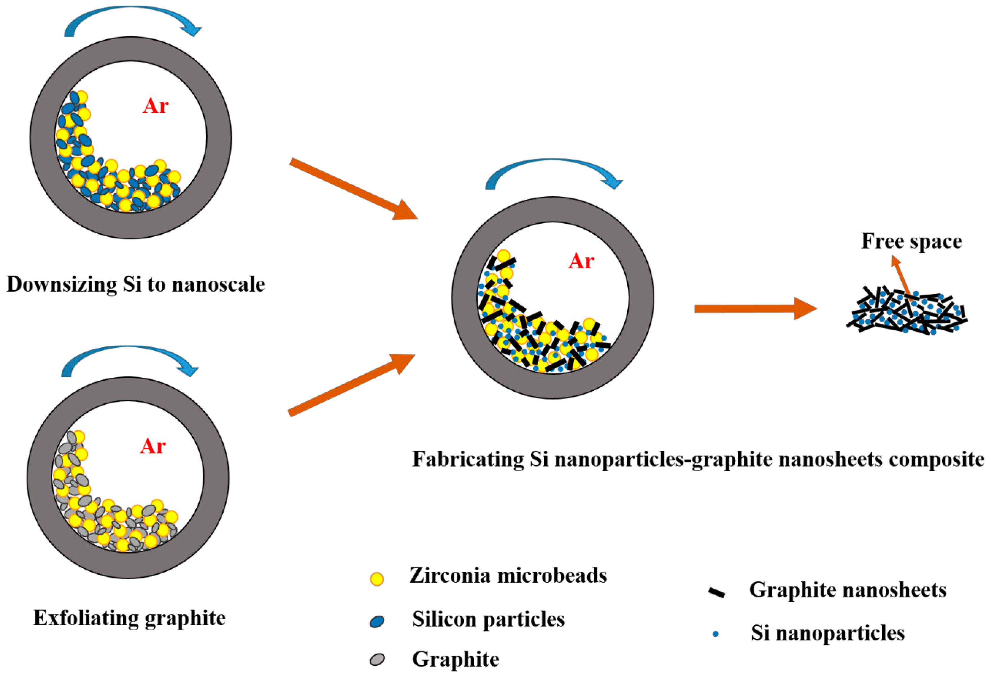
2.2. Preparation of Si Nanoparticle–Graphite Nanosheet Composites

Si nanoparticle–graphite nanosheet composites were prepared through a ball milling process by adopting a Fritsch PULVERISETTE7 premium line machine. The vials were sealed under an Ar atmosphere after filling with 1 g of graphite nanosheets (GNs) and Si nanoparticles (SiNPs) with a ratio of 9:1. The milling was carried out using zirconia microbeads, a ball-to-powder ratio of 28:1, with a rotation speed of 600 rpm. Three SiNPs-GNs composites with 40, 140, and 250 nm SiNPs were produced, denoted as 40SiNPs-GNs, 140SiNPs-GNs, and 250SiNPs-GNs, respectively. The overall preparation procedure of SiNPs-GNs composites is schematically presented in Figure 1.

2.3. Structural Characterizations

Powder X-ray diffraction was carried out using a PANalytical X’pert pro instrument with Cu Kα X-ray of λ = 1.54181 Å, an operating voltage of 40 kV, and 30 mA current. The scanning electron microscopy (SEM) characterization of the powders was performed by a Hitachi S4500 Zeiss Supra 55VP instrument. To support SEM analysis, structural investigations were further carried out using transmission electron microscopy (TEM), using a JEOL JEM 2100 instrument operated at 200 kV with the LaB6 beam source. TEM bright-field images were obtained using a Gatan Orius SC1000 camera and Gatan Digital Micrograph software. The Energy-dispersive X-ray spectroscopy (EDS) maps were acquired using a JEOL JD2300 energy-dispersive X-ray analyzer installed on the JEOL JEM 2100 microscope. Si nanoparticles were quantitatively analyzed from SEM images by adopting Microstructural Image Processing (MIP) software [24].

2.4. Electrochemical Measurements

To examine the battery performance of the SiNPs-GNs composites, graphite nanosheets, and Si nanoparticles, the active material powders were mixed with carbon black and a binder in a weight ratio of 8:1:1 for SiNPs-GNs and GNs, and 6:2:2 for SiNPs. Then, they were added to deionized water or NMP (N-methyl-2-pyrrolidone) solvent and stirred overnight to obtain a homogeneous slurry. The binders of Gum Arabic and PVdF (polyvinylidene fluoride) were used for Si-based and GN electrodes, respectively. The slurries were coated on copper foils and vacuum-dried overnight at 90 °C. The electrodes with an active material weight of around 1 mg were assembled into coin-type CR2032 cells inside the Ar glovebox. The electrochemical tests were conducted by the half-cells containing Li metal as both reference and counter electrodes, a microporous polyethylene film (MTI Corporation, California, CA, USA) as a separator, and 1 M LiPF6 salt dissolved in a mixture of ethylene carbonate (EC), dimethyl carbonate (DMC), and diethyl carbonate (DEC) with a volume ratio of 1:1:1 as the electrolyte. The electrolyte used for the Si-based electrodes contained 10% FEC (fluoroethylene carbonate).
The electrochemical performance of the half-cells was evaluated through galvanostatic cycling tests using a Land battery testing CT2001A system (Wuhan Land Electronics Co Ltd., Wuhan, China) and LANDdt software for data collection. The cells were discharge–charged within the voltage range of 0.005–2 V vs. Li+/Li. Cyclic voltammetry (CV) tests were conducted via a 1470E cell test system (Solartron, Solartron Leiceste, Leicester, England). For the CV tests, the working electrodes were scanned at 0.05 mV S−1 in the potential range of 0.01–2 V vs. Li+/Li.

3. Results and Discussion

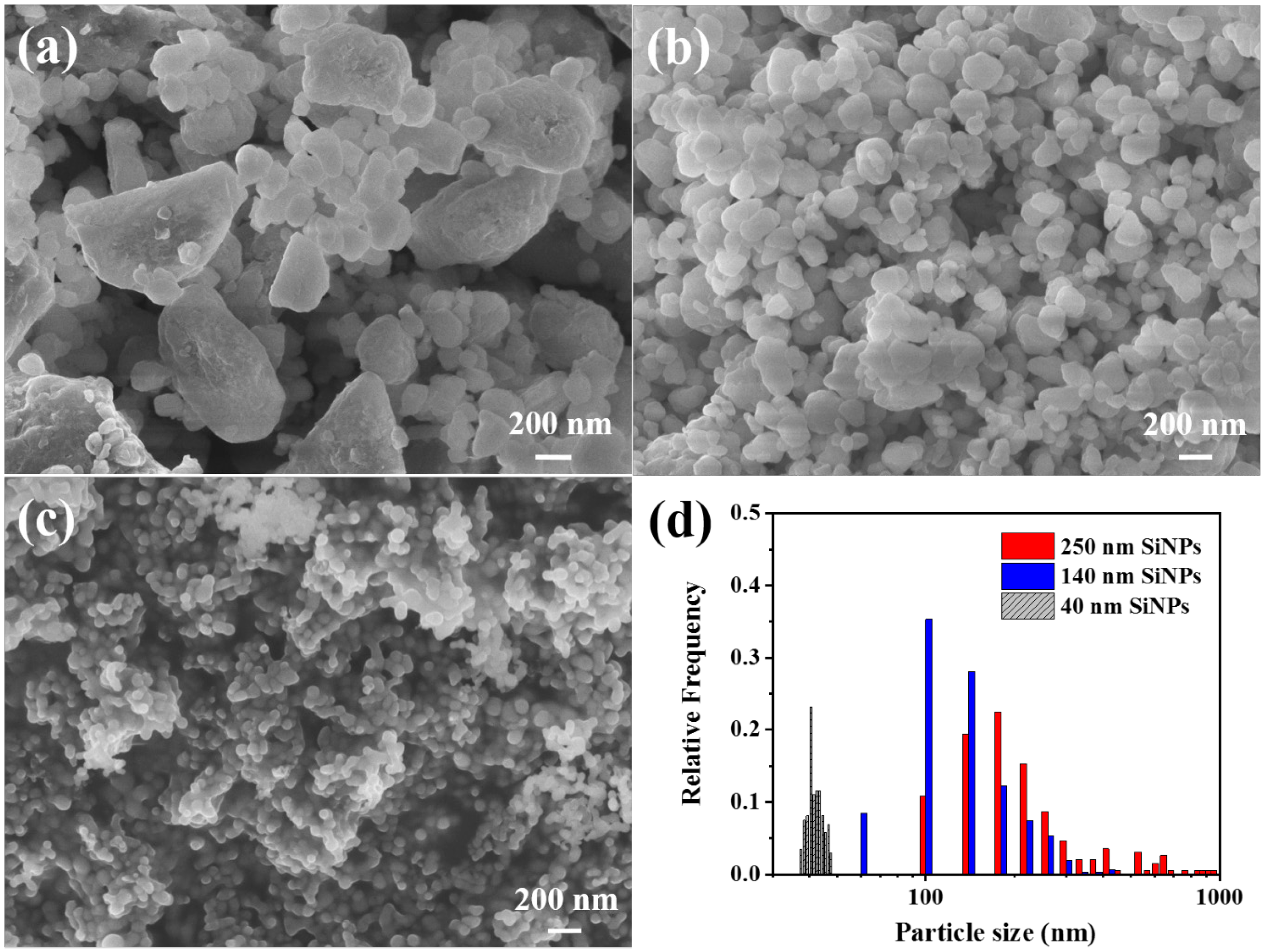
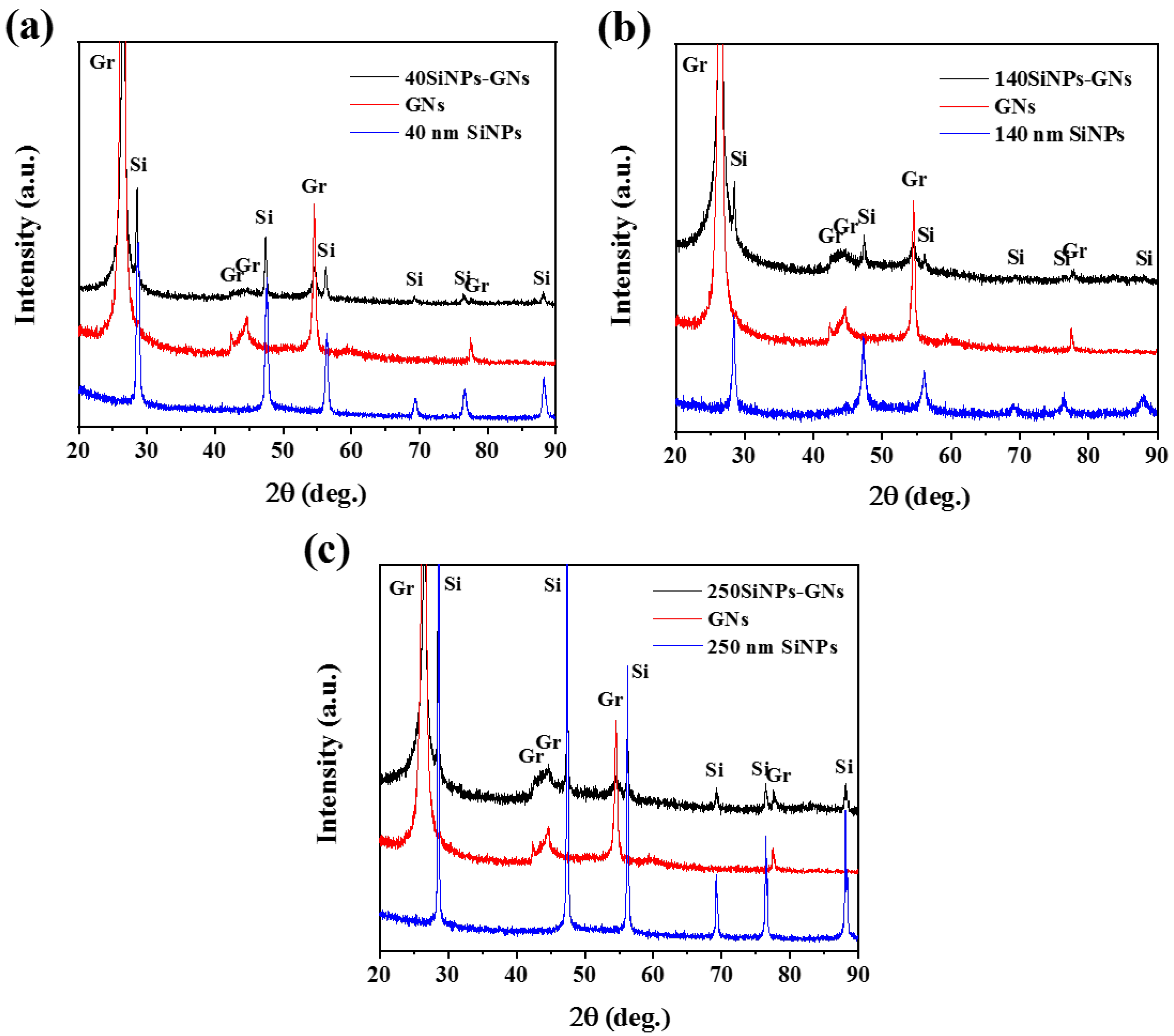
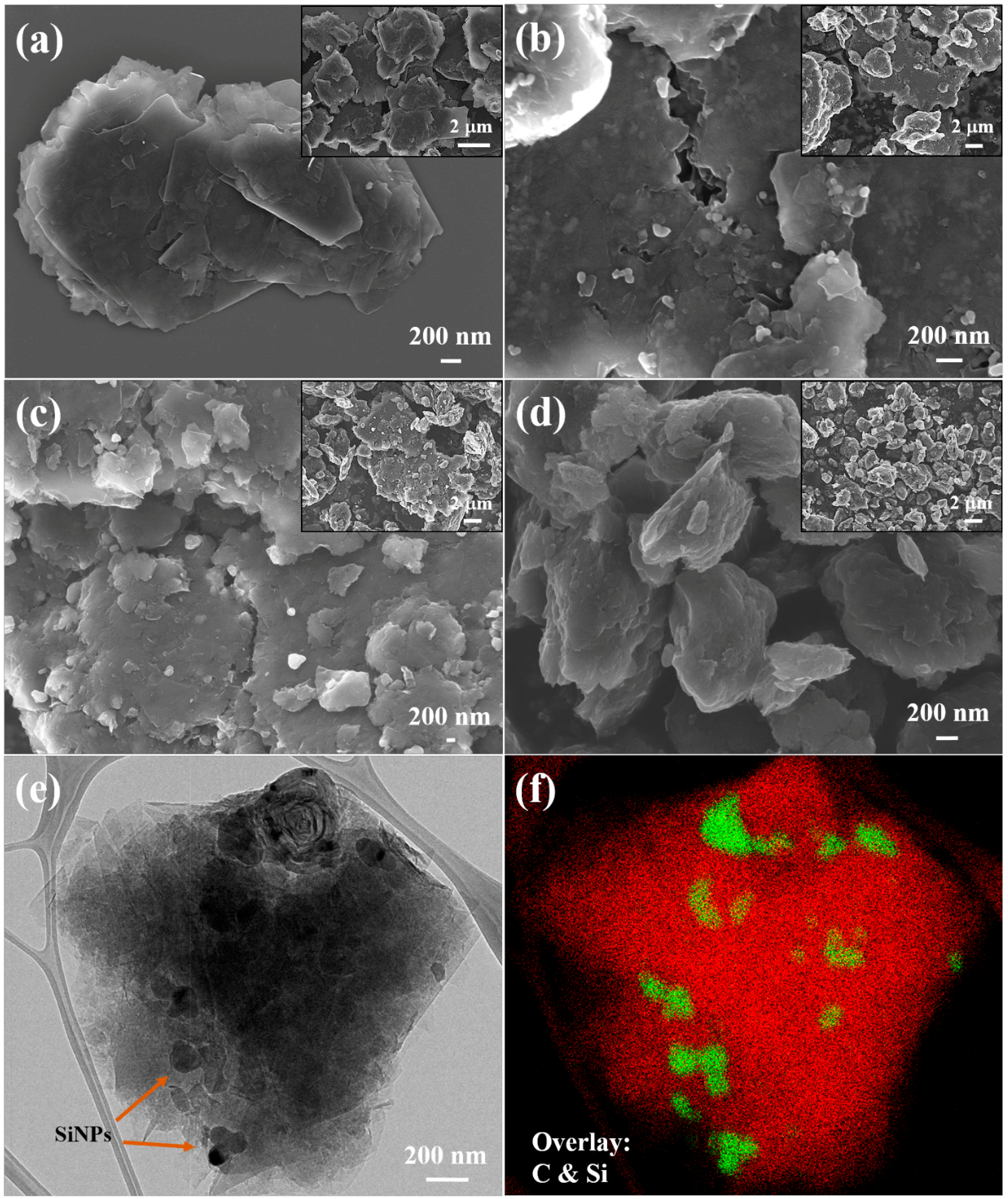
3.1. Structural Characterization

Figure 2 shows SEM images of silicon nanoparticles with various particle sizes of 40, 140, and 250 nm, which were used for the preparation of SiNPs-GNs composites. The particle size distribution of various SiNPs is represented in Figure 2d. For each powder, a total of ~100 particles were measured to achieve the particle size distribution and the average particle size. It is observed that 40 nm and 140 nm SiNPs have a more homogenous size distribution than 250 nm SiNPs, with a wider range of particle size. The 140 nm SiNPs produced by ball milling are crystalline, according to the XRD patterns in Figure 3b. Therefore, they are slightly below the critical limit of ~150 nm for crystalline Si to resist pulverization [25].
Figure 3 represents the XRD patterns of the SiNPs-GNs composites together with the primary materials of GNs and SiNPs. The XRD peaks of the GNs and SiNPs are well-matched with their corresponding peaks in the SiNPs-GNs composites. The 140 nm SiNPs show broader XRD peaks than 250 nm SiNPs, which is related to the crystallite size reduction by increasing ball milling time. The average crystallite sizes of 40, 140, and 250 nm SiNPs were measured to be 16.9, 18.5, and 56.5 nm, respectively, using the Scherrer formula:
L = K λ   β . C o s θ
where λ is the X-ray wavelength in nanometers, K is normally taken as 0.9, as a constant related to crystallite shape, and β is the peak width of the diffraction peak profile at half maximum height in radians [26]. However, 140 nm SiNPs have broader peaks than 40 nm SiNPs, which can be due to the created strain in the particles by ball milling.
SEM images of the 40SiNPs-GNs, 140SiNPs-GNs, and 250SiNPs-GNs composites are shown in Figure 4. Figure 4a also represents the starting material of graphite nanosheets made by ball milling of commercial graphite, which consists of nanosheets with the thickness of 34–53 nm and the length of 140–800 nm [23]. The low- and high-magnification SEM images of 40SiNPs-GNs show that the SiNPs are inserted among graphite nanosheets and form nanocomposite clusters with a layered structure, in which thin graphite layers are distinguished from SiNPs (Figure 4b). Such a structure may provide better conductivity for SiNPs-GNs composite electrodes and free space for Si expansion. Images of 140SiNPs-GNs also show a layered structure with embedded SiNPs among GNs. On the other hand, 250SiNPs-GNs composite with 250 nm SiNPs exhibit a different structure in which SiNPs are just surrounded by thin graphite flakes and not visible in the SEM image. Additional structural analysis of the 40SiNPs-GNs composite was carried out by TEM. The bright-field image demonstrates the structure of the nanocomposite consisting of the 40 nm SiNPs encapsulated between graphite nanosheets (Figure 4e). In the same location, an overlay of EDS elemental maps of Si and graphite was obtained which shows the distribution of the 40 nm SiNPs between graphite nanosheets (Figure 4f). Therefore, TEM analysis also shows that 40 nm SiNPs are well-embedded between graphite nanosheets.

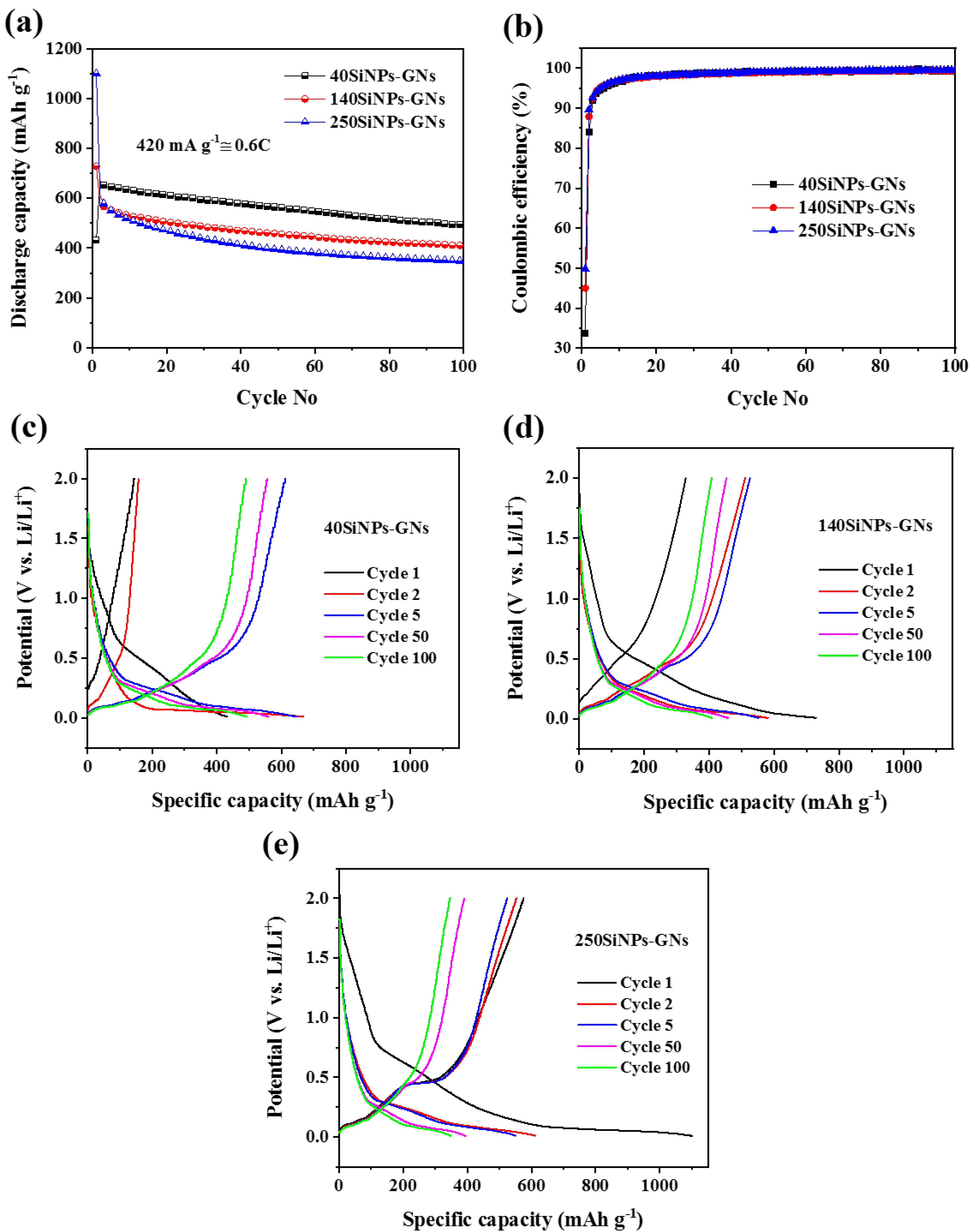
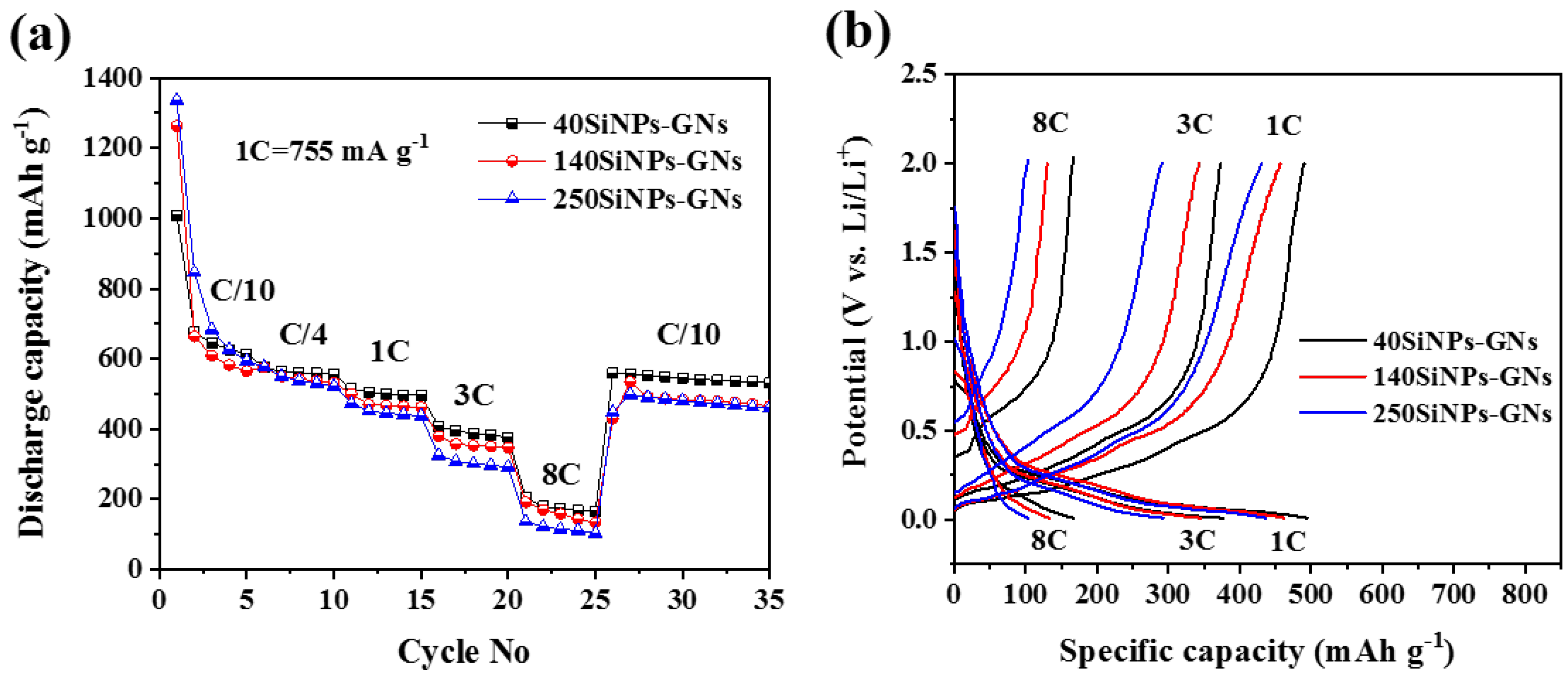
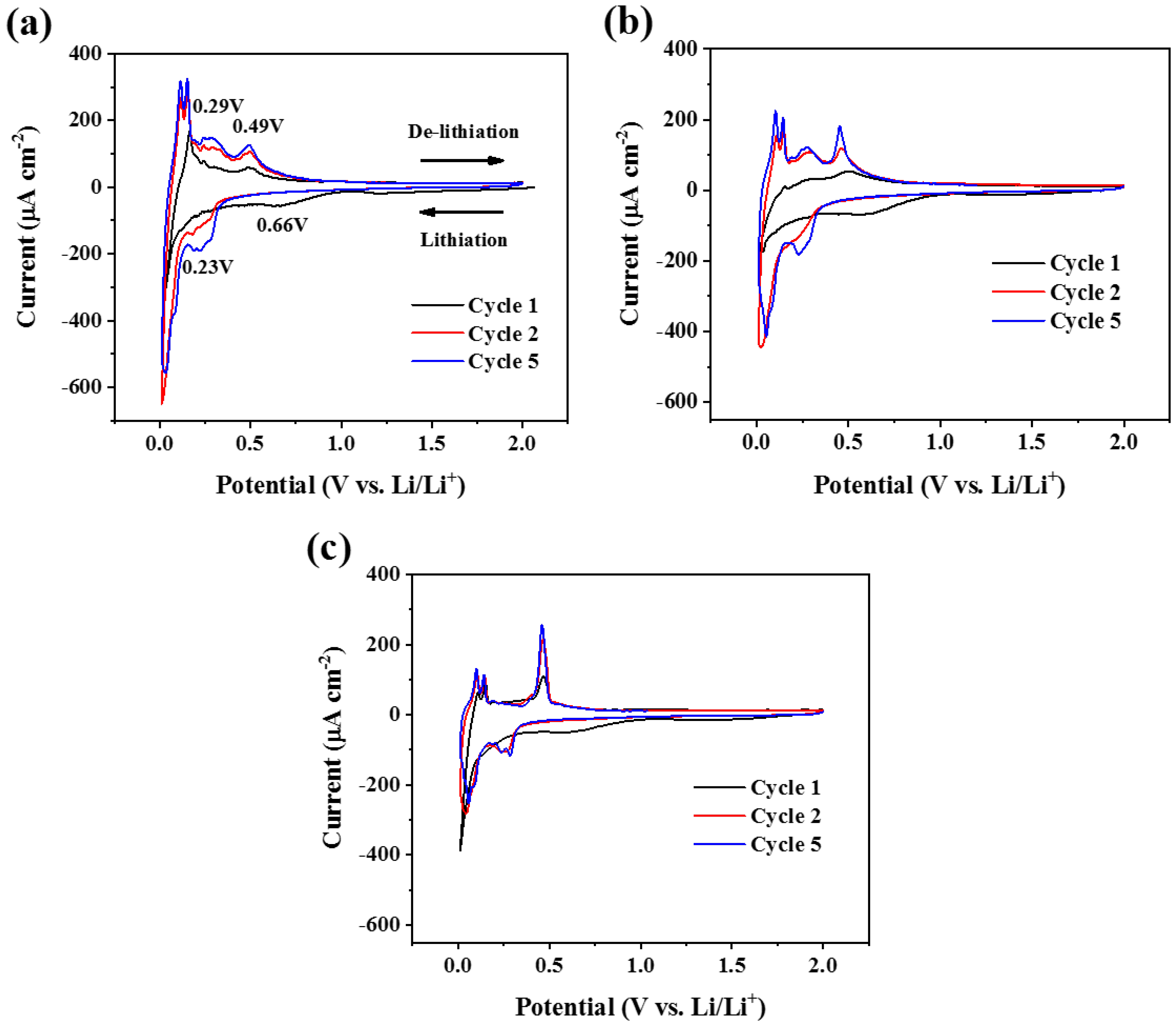
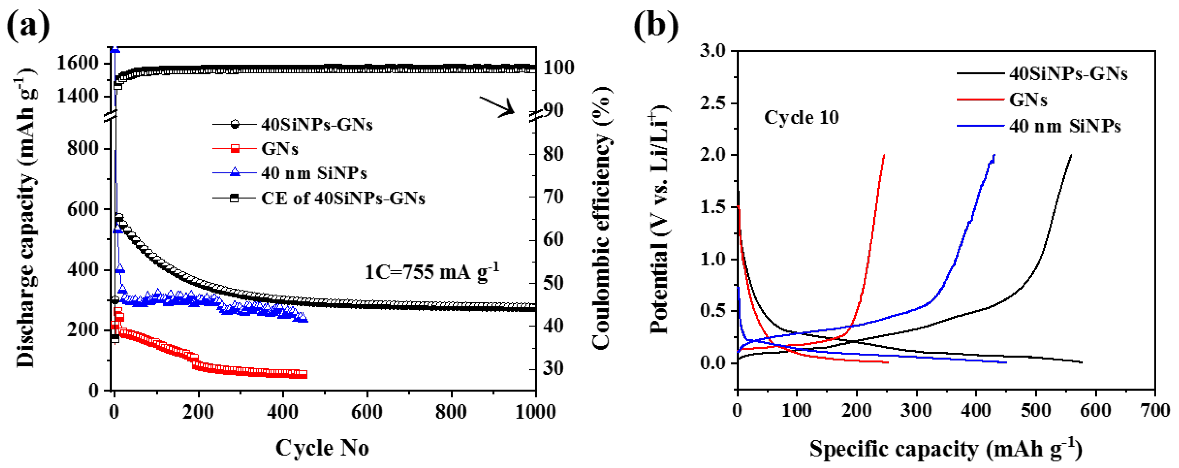
3.2. Electrochemical Characterization

LIB performance of the SiNPs-GNs composite anodes with various sizes of SiNPs was investigated. Regarding the theoretical capacity of silicon (~4200 mAh g−1) and graphite (~372 mAh g−1), and the weight ratio between Si and graphite in the composite (1:9), the theoretical capacity of the produced Si–graphite nanocomposites is ~755 mAh g−1, derived from the following equation:
Cth = CSiWSi + CGrWGr
where CSi and CGr are the theoretical capacities of Si and Gr, and WSi and WGr are the weight percentage of Si and Gr in the composite, respectively.
Figure 5a compares the cycling performance among three electrodes of 40SiNPs-GNs, 140SiNPs-GNs, and 250SiNPs-GNs at a current density of 420 mA g−1 (~0.6C). Composite electrodes of 40SiNPs-GNs, 140SiNPs-GNs, and 250SiNPs-GNs record a discharge capacity of 493, 408, and 348 mAh g−1 after 100 cycles, respectively. The capacity retention of the 40SiNPs-GNs electrode after 100 cycles is 65% concerning the theoretical capacity of 755 mAh g−1, whereas it is 54% and 46% for the 140SiNPs-GNs and 250SiNPs-GNs, respectively. Therefore, increasing the size of SiNPs in SiNPs-GNs composites leads to decreasing capacity of the electrode over cycling. This is likely because the generated internal stress inside SiNPs due to volume expansion during cycling is higher for bigger SiNPs, which leads to more cracking and pulverization of silicon, followed by the instability of the SEI layer and electrical contact loss of silicon particles from the graphite matrix [27]. Considering the morphology of SiNPs-GNs composites represented in the SEM and TEM images, 40 nm SiNPs in 40SiNPs-GNs composite are effectively encapsulated among graphite nanosheets. In comparison, 250 nm SiNPs in 250SiNPs-GNs composite are just surrounded by thin graphite flakes. Therefore, cyclability improvement of the 40SiNPs-GNs can also be due to the indirect exposure of Si to electrolyte, leading to a limited SEI deposition on Si over cycling and formation of a more stable SEI layer on graphite nanosheets [16,28]. Engagement of the Si nanoparticles and graphite nanosheets in 40SiNPs-GNs and 140SiNPs-GNs composites provides some free spaces around SiNPs in the composite structures (Figure 1 and Figure 4). This free space is beneficial to accommodate the volume change of Si. The 40 nm SiNPs can also provide shorter diffusion pathways for the Li+ ions and electrons inside the electrodes.
The first cycle discharge capacities for the 40SiNPs-GNs, 140SiNPs-GNs, and 250SiNPs-GNs electrodes were measured to be at 430, 729, and 1100 mAh g−1, respectively. The lower first cycle capacity of the composite electrodes with finer SiNPs may be due to the limited contact of the well-encapsulated finer SiNPs between GNs with electrolyte, followed by reduced intercalation/de-intercalation of the Li+ ions [25].
Figure 5b shows the Coulombic efficiency (CE) values of 40SiNPs-GNs, 140SiNPs-GNs, and 250SiNPs-GNs electrodes, which are measured to be 34%, 45%, and 50% in the first cycle, respectively. Low CE in the first cycles for the composites with finer SiNPs can be associated with a higher interfacial area of fine Si particles/electrolyte and formation of a large SEI layer [14]. CE of all the electrodes reaches over 99% after 50 cycles.
The corresponding discharge (Li+ insertion) and charge (Li+ extraction) profiles of the electrodes with the cut-off potential range of 0.01–2.00 V are presented in Figure 5c–e. The higher first cycle capacity for the 250SiNPs-GNs electrode is obvious in the voltage profiles; however, the 40SiNPs-GNs electrode shows higher capacity and better stability over 100 cycles. A voltage plateau is observed below 0.5 V in the charge curves of all the electrodes, which corresponds to de-lithiation of SiNPs [20]. This plateau is bigger in the first cycles of 250SiNPs-GNs compared to 40SiNPs-GNs and 140SiNPs-GNs; however, it is more obvious in the 100th cycle for 40SiNPs-GNs and 140SiNPs-GNs. Thus, the bigger SiNPs show more de-alloying in the first cycles, while the finer SiNPs deliver higher Li+ extraction in the following cycles. The mechanism can again be explained by the effect of SiNP size reduction on the formation of lower internal stress inside Si, good encapsulation of SiNPs between graphite nanosheets, and free space creation in SiNPs-GNs composites, which leads to the SEI layer stability and improved conductivity. Furthermore, in voltage profiles of 250SiNPs-GNs, the bigger plateaus of Li+ extraction from Si in the first cycles verify the explanation for the higher first cycle capacity of the 250SiNPs-GNs electrode over 40SiNPs-GNs and 140SiNPs-GNs, decreasing the graphite barrier for lithiation/de-lithiation of Si.
Figure 6a,b exhibit the high-rate performance of SiNPs-GNs composite electrodes through multi-current galvanostatic discharge/charge examinations. The electrodes were evaluated at various current rates from 0.1 to 8C (1C = 755 mA g−1) in the five-cycle steps followed by the cycling at the primary current rate of 0.1C. The 40SiNPs-GNs, 140SiNPs-GNs, and 250SiNPs-GNs electrodes exhibit a discharge capacity of 407, 379, and 325 at 3C, and 205, 192, and 136 mAh g−1 at 8C, respectively. The results show better rate capability of the 40SiNPs-GNs electrode, particularly at higher current rates. It is noticed that the 250SiNPs-GNs electrode delivers the highest first discharge capacity of 1336 mAh g−1 at 0.1C compared to 1262 and 1009 mAh g−1 for 140SiNPs-GNs and 40SiNPs-GNs, respectively. This trend is also compatible with the cycling results at the low constant current density of 0.6C. All electrodes indicate a good recoverability when the current rate switches back to 0.1C after cycling at high current rates; however, the SiNPs-GNs composite electrode with 40 nm SiNPs exhibits the highest discharge capacity of 559 mAh g−1 at the returned current density of 0.1C.
Cyclic voltammograms of the SiNPs-GNs electrodes at a scan rate of 0.05 mV s−1 are shown in Figure 7. It can be seen in the CV of all the electrodes that after the initial activation of the electrode material, the intensity of anodic and cathodic peaks increases in the subsequent cycles [29]. All the electrodes exhibit a broad peak in the first discharge at around 0.66 V vs. Li/Li+, which is related to the solid–electrolyte interphase (SEI) layer formed on the surface of the electrodes. In the following discharge curves, cathodic peaks are observed at ~0.23 V and ~0.07 V, which correspond to the lithiation of Si [30] and exfoliated graphite, respectively.
In the anodic scan of the SiNPs-GNs electrode, the first three peaks located at ~0.11 V, ~0.15, and ~0.24 V can be attributed to the de-lithiation of graphite [18]. The de-alloying process of Si takes place at ~0.29 V and ~0.49 V, which are associated with the de-insertion of the Li+ ions from highly lithiated Si and less lithiated Si, respectively [30,31]. With increasing size of SiNPs, the intensity of the anodic peaks related to the Li+ ions de-insertion from Si increases, while it shows a reduction for the graphite peaks. This is compatible with voltage profiles in Figure 5c–e, in which the charge plateau of the first cycles below 0.5 V, related to Si de-lithiation, becomes noticeable with increasing SiNPs size. Moreover, limited lithiation/de-lithiation of finer SiNPs inside the GN matrix in the first cycles is further demonstrated by lower intensity of the de-lithiation peaks of 40 nm SiNPs, which can be due to efficient SiNP enclosure between graphite nanosheets.
High-rate performance of the 40SiNPs-GNs electrode was further investigated compared with two control electrodes of GNs and 40 nm SiNPs at a high current density of 1C = 755 mA g−1 (Figure 8). The 40SiNPs-GNs electrode delivers a discharge capacity of 276 mAh g−1 after 1000 cycles, while GN and 40 nm SiNP electrodes show capacity dropping and failure after around 15 and 400 cycles (Figure 8a). After 100 cycles, capacity retention of the 40SiNPs-GNs, GNs, and 40 nm SiNPs is 57%, 6.99%, and 42% of their theoretical capacities, respectively. Therefore, the 40SiNPs-GNs electrode exhibits superior rate capability compared to GN and 40 nm SiNP electrodes. Irreversible capacity loss of the 40SiNPs-GNs composite electrode leads to low Coulombic efficiency in the first cycle, while it reaches 95% and 99% after five and fifty cycles, respectively. The high CE of the 40SiNPs-GNs electrode shows that the SEI layer remains stable during cycling. The corresponding discharge–charge profiles of the 10th cycle of the 40SiNPs-GNs, GNs, and 40 nm SiNPs electrodes in Figure 8b represent that Si-based anodes show significant redox potentials in the range of 0.1–0.5 V; however, their plateaus are steeper than those of GNs.

4. Conclusions

A facile ball milling process was established to prepare a simple Si nanoparticle–graphite nanosheet composite with no chemical additives/embedded elements/coating/heat treatment in their synthesis process. The effect of the size of Si nanoparticles on the structure and LIB performance of the SiNPs-GNs composite was investigated. SEM and TEM characterizations showed that decreasing the size of SiNPs results in the formation of a SiNPs-embedded-GNs structure with effective encapsulation of SiNPs among graphite nanosheets and free space around SiNPs. This structure showed an increased capacity and rate capability. The mechanism can be explained by the reduced exposure of SiNPs to the electrolyte and formation of free space in the composite structure for SiNP expansion during lithiation, leading to SEI layer stability and improved conductivity. In addition, the generated stress in Si particles due to volume change during lithiation/de-lithiation can be buffered in finer SiNPs. Reduced diffusion pathways for the Li+ ions and electrons can be another helpful factor in increasing the rate capability. The composite of 40 nm Si nanoparticle–graphite nanosheet delivers enhanced high-rate performance over graphite nanosheets and 40 nm SiNPs. It was shown that good encapsulation of finer SiNPs inside graphite nanosheets limits the Li+ insertion/de-insertion of Si; however, the overall influence of this structure results in the improved cycling and rate performance of the composite. The post-cycling analysis, including XRD, SEM, and EIS analysis, will be presented in the future to realize the structural changes and cycling mechanisms and obtain optimum composite structures.

Author Contributions

Conceptualization, V.G.A.; Data curation, V.G.A.; Formal analysis, V.G.A.; Investigation, V.G.A.; Methodology, V.G.A.; Resources, Y.C.; Software, V.G.A.; Supervision, Y.C.; Visualization, V.G.A.; Writing—original draft, V.G.A.; Writing—review and editing, V.G.A. and M.M.R. All authors have read and agreed to the published version of the manuscript.

Funding

This research received no external funding.

Institutional Review Board Statement

Not applicable.

Informed Consent Statement

Not applicable.

Data Availability Statement

The raw data supporting the conclusions of this article will be made available by the authors on request.

Conflicts of Interest

The authors declare no conflicts of interest.

References

  1. Etacheri, V.; Marom, R.; Elazari, R.; Salitra, G.; Aurbach, D. Challenges in the development of advanced Li-ion batteries: A review. Energy Environ. Sci. 2011, 4, 3243–3262. [Google Scholar] [CrossRef]
  2. Kang, B.; Ceder, G. Battery materials for ultrafast charging and discharging. Nature 2009, 458, 190–193. [Google Scholar] [CrossRef]
  3. Wu, Z.-S.; Ren, W.; Xu, L.; Li, F.; Cheng, H.-M. Doped graphene sheets as anode materials with superhigh rate and large capacity for lithium ion batteries. ACS Nano 2011, 5, 5463–5471. [Google Scholar] [CrossRef] [PubMed]
  4. Tang, Y.; Zhang, Y.; Li, W.; Ma, B.; Chen, X. Rational material design for ultrafast rechargeable lithium-ion batteries. Chem. Soc. Rev. 2015, 44, 5926–5940. [Google Scholar] [CrossRef]
  5. Casimir, A.; Zhang, H.; Ogoke, O.; Amine, J.C.; Lu, J.; Wu, G. Silicon-based anodes for lithium-ion batteries: Effectiveness of materials synthesis and electrode preparation. Nano Energy 2016, 27, 359–376. [Google Scholar] [CrossRef]
  6. Wang, L.; Gao, B.; Peng, C.; Peng, X.; Fu, J.; Chu, P.K.; Huo, K. Bamboo leaf derived ultrafine Si nanoparticles and Si/C nanocomposites for high-performance Li-ion battery anodes. Nanoscale 2015, 7, 13840–13847. [Google Scholar] [CrossRef]
  7. Ryu, J.; Hong, D.; Choi, S.; Park, S. Synthesis of Ultrathin Si Nanosheets from Natural Clays for Lithium-Ion Battery Anodes. ACS Nano 2016, 10, 2843–2851. [Google Scholar] [CrossRef]
  8. Song, T.; Xia, J.; Lee, J.-H.; Lee, D.H.; Kwon, M.-S.; Choi, J.-M.; Wu, J.; Doo, S.K.; Chang, H.; Park, W.I. Arrays of sealed silicon nanotubes as anodes for lithium ion batteries. Nano Lett. 2010, 10, 1710–1716. [Google Scholar] [CrossRef]
  9. Nguyen, H.T.; Yao, F.; Zamfir, M.R.; Biswas, C.; So, K.P.; Lee, Y.H.; Kim, S.M.; Cha, S.N.; Kim, J.M.; Pribat, D. Highly Interconnected Si Nanowires for Improved Stability Li-Ion Battery Anodes. Adv. Energy Mater. 2011, 1, 1154–1161. [Google Scholar] [CrossRef]
  10. Shen, C.; Ge, M.; Luo, L.; Fang, X.; Liu, Y.; Zhang, A.; Rong, J.; Wang, C.; Zhou, C. In Situ and Ex Situ TEM Study of Lithiation Behaviours of Porous Silicon Nanostructures. Sci. Rep. 2016, 6, 31334. [Google Scholar] [CrossRef]
  11. Xia, F.; Kwon, S.; Lee, W.W.; Liu, Z.; Kim, S.; Song, T.; Choi, K.J.; Paik, U.; Park, W.I. Graphene as an Interfacial Layer for Improving Cycling Performance of Si Nanowires in Lithium-Ion Batteries. Nano Lett. 2015, 15, 6658–6664. [Google Scholar] [CrossRef]
  12. Zhang, L.; Wang, Y.; Kan, G.; Zhang, Z.; Wang, C.; Zhong, Z.; Su, F. Scalable synthesis of porous silicon/carbon microspheres as improved anode materials for Li-ion batteries. RSC Adv. 2014, 4, 43114–43120. [Google Scholar] [CrossRef]
  13. Zhu, B.; Jin, Y.; Tan, Y.; Zong, L.; Hu, Y.; Chen, L.; Chen, Y.; Zhang, Q.; Zhu, J. Scalable Production of Si Nanoparticles Directly from Low Grade Sources for Lithium-Ion Battery Anode. Nano Lett. 2015, 15, 5750–5754. [Google Scholar] [CrossRef]
  14. Sun, Y.; Liu, N.; Cui, Y. Promises and challenges of nanomaterials for lithium-based rechargeable batteries. Nat. Energy 2016, 1, 16071. [Google Scholar] [CrossRef]
  15. Terranova, M.L.; Orlanducci, S.; Tamburri, E.; Guglielmotti, V.; Rossi, M. Si/C hybrid nanostructures for Li-ion anodes: An overview. J. Power Sources 2014, 246, 167–177. [Google Scholar] [CrossRef]
  16. Wu, H.; Zheng, G.; Liu, N.; Carney, T.J.; Yang, Y.; Cui, Y. Engineering Empty Space between Si Nanoparticles for Lithium-Ion Battery Anodes. Nano Lett. 2012, 12, 904–909. [Google Scholar] [CrossRef]
  17. Jo, Y.N.; Kim, Y.; Kim, J.S.; Song, J.H.; Kim, K.J.; Kwag, C.Y.; Lee, D.J.; Park, C.W.; Kim, Y.J. Si–graphite composites as anode materials for lithium secondary batteries. J. Power Sources 2010, 195, 6031–6036. [Google Scholar] [CrossRef]
  18. Yoon, Y.; Jee, S.; Lee, S.; Nam, S. Nano Si-coated graphite composite anode synthesized by semi-mass production ball milling for lithium secondary batteries. Surf. Coat. Technol. 2011, 206, 553–558. [Google Scholar] [CrossRef]
  19. Yim, C.-H.; Courtel, F.M.; Abu-Lebdeh, Y. A high capacity silicon–graphite composite as anode for lithium-ion batteries using low content amorphous silicon and compatible binders. J. Mater. Chem. A 2013, 1, 8234–8243. [Google Scholar] [CrossRef]
  20. Wang, A.; Liu, F.; Wang, Z.; Liu, X. Self-assembly of silicon/carbon hybrids and natural graphite as anode materials for lithium-ion batteries. RSC Adv. 2016, 6, 104995–105002. [Google Scholar] [CrossRef]
  21. Cabello, M.; Gucciardi, E.; Herrán, A.; Carriazo, D.; Villaverde, A.; Rojo, T. Towards a High-Power Si@graphite Anode for Lithium Ion Batteries through a Wet Ball Milling Process. Molecules 2020, 25, 2494. [Google Scholar] [CrossRef]
  22. Li, P.; Kim, H.; Myung, S.-T.; Sun, Y.-K. Diverting Exploration of Silicon Anode into Practical Way: A Review Focused on Silicon-Graphite Composite for Lithium Ion Batteries. Energy Storage Mater. 2021, 35, 550–576. [Google Scholar] [CrossRef]
  23. Ghanooni Ahmadabadi, V.; Rahman, M.M.; Chen, Y. A Study on High-Rate Performance of Graphite Nanostructures Produced by Ball Milling as Anode for Lithium-Ion Batteries. Micromachines 2023, 14, 191. [Google Scholar] [CrossRef]
  24. Available online: https://metsofts.ir/microstructure-image-processing/ (accessed on 1 February 2024).
  25. Gu, M.; He, Y.; Zheng, J.; Wang, C. Nanoscale silicon as anode for Li-ion batteries: The fundamentals, promises, and challenges. Nano Energy 2015, 17, 366–383. [Google Scholar] [CrossRef]
  26. Monshi, A.; Foroughi, M.R.; Monshi, M.R. Modified Scherrer equation to estimate more accurately nano-crystallite size using XRD. World J. Nano Sci. Eng. 2012, 2, 154–160. [Google Scholar] [CrossRef]
  27. Rahman, M.; Song, G.; Bhatt, A.I.; Wong, Y.C.; Wen, C. Nanostructured Silicon Anodes for High-Performance Lithium-Ion Batteries. Adv. Funct. Mater. 2016, 26, 647–678. [Google Scholar] [CrossRef]
  28. Zhang, M.; Zhang, T.; Ma, Y.; Chen, Y. Latest development of nanostructured Si/C materials for lithium anode studies and applications. Energy Storage Mater. 2016, 4, 1–14. [Google Scholar] [CrossRef]
  29. Shi, L.; Wang, W.; Wang, A.; Yuan, K.; Yang, Y. Facile synthesis of scalable pore-containing silicon/nitrogen-rich carbon composites from waste contact mass of organosilane industry as anode materials for lithium-ion batteries. J. Mater. Chem. A 2014, 2, 20213–20220. [Google Scholar] [CrossRef]
  30. Kim, S.Y.; Lee, J.; Kim, B.H.; Kim, Y.J.; Yang, K.S.; Park, M.S. Facile Synthesis of Carbon-Coated Silicon/Graphite Spherical Composites for High-Performance Lithium-Ion Batteries. ACS Appl. Mater. Interfaces 2016, 8, 12109–12117. [Google Scholar] [CrossRef] [PubMed]
  31. Zhou, Y.; Guo, H.; Yang, Y.; Wang, Z.; Li, X.; Zhou, R.; Peng, W. Facile synthesis of silicon/carbon nanospheres composite anode materials for lithium-ion batteries. Mater. Lett. 2016, 168, 138–142. [Google Scholar] [CrossRef]
Figure 1. Schematic of the fabrication of Si nanoparticle–graphite nanosheet composite via a facile ball milling process.
Electrochem 05 00009 g001
Figure 2. SEM images of ball-milled and commercial Si nanoparticles with various sizes as the starting materials for Si–graphite nanocomposites: 250 nm SiNPs (a), 140 nm SiNPs (b), 40 nm SiNPs (c), and particle size distribution of SiNPs (d).
Electrochem 05 00009 g002
Figure 3. XRD patterns of SiNPs-GNs composites and their primary materials, including GNs and SiNPs: 40SiNPs-GNs (a), 140SiNPs-GNs (b), and 250SiNPs-GNs (c).
Electrochem 05 00009 g003
Figure 4. Low- and high-magnification SEM images of graphite nanosheets (a) and SiNPs-GNs composites with various sizes of SiNPs: 40SiNPs-GNs (b), 140SiNPs-GNs (c), and 250SiNPs-GNs (d). TEM characterization of 40SiNPs-GNs composite; bright-field image (e) and the corresponding overlay EDS elemental maps of graphite and Si (f): (red) graphite, (green) Si.
Electrochem 05 00009 g004
Figure 5. Electrochemical performances of SiNPs-GNs composite with various sizes of Si nanoparticles: (a) cycling stability at a current rate of 420 mA g−1 (1C = 755 mA g−1); (b) Coulombic efficiency; (ce) corresponding galvanostatic discharge/charge profiles for the selected cycles.
Electrochem 05 00009 g005
Figure 6. Rate performance (a) and corresponding discharge/charge potential profiles obtained at high current rates of 1C, 3C, and 8C (b) of SiNPs-GNs composite with various sizes of Si nanoparticles.
Electrochem 05 00009 g006
Figure 7. Cyclic voltammograms of SiNPs-GNs composites with various sizes of Si nanoparticles at a scan rate of 0.05 mV s−1: 40SiNPs-GNs (a), 140SiNPs-GNs (b), 250SiNPs-GNs (c).
Electrochem 05 00009 g007
Figure 8. Cycling stability of the 40SiNPs-GNs composite electrode at a current density of 1C = 755 mA g−1 (a) and corresponding galvanostatic discharge–charge profiles of the 10th cycle (b). Cycling data of the GNs and 40 nm SiNPs at the same current rate are comparatively presented.
Electrochem 05 00009 g008
Disclaimer/Publisher’s Note: The statements, opinions and data contained in all publications are solely those of the individual author(s) and contributor(s) and not of MDPI and/or the editor(s). MDPI and/or the editor(s) disclaim responsibility for any injury to people or property resulting from any ideas, methods, instructions or products referred to in the content.

