Article

A Nitrogen- and Carbon-Present Tin Dioxide-Supported Palladium Composite Catalyst (Pd/N-C-SnO2)

1
Hebei Technology Innovation Center for Energy Conversion Materials and Devices, Hebei Key Laboratory of Inorganic Nano-Materials, College of Chemistry and Materials Science, Hebei Normal University, Shijiazhuang 050024, China
2
Hebei LingDian New Energy Technology Ltd. Co., Tangshan 064200, China
*
Author to whom correspondence should be addressed.
Electrochem 2024, 5(4), 482-505; https://doi.org/10.3390/electrochem5040032
Submission received: 5 July 2024 / Revised: 20 August 2024 / Accepted: 19 September 2024 / Published: 13 November 2024

Abstract

:
For the first time, nitrogen- and carbon-present tin dioxide-supported palladium composite catalysts (denoted as Pd/N-C-SnO2) were prepared via an HCH method (HCH is the abbreviation for the hydrothermal process–calcination–hydrothermal process preparation process). In this work, firstly, three catalyst carriers (denoted as cc) were prepared using a hydrothermal-process-aided calcination method, and catalyst carriers prepared using ammonia monohydrate (NH3∙H2O), N,N-dimethylformamide (C3H7NO) and triethanolamine (C6H15NO3) as the nitrogen sources were nominated as cc1, cc2 and cc3, respectively. Secondly, these catalyst carriers were reacted with palladium oxide monohydrate (PdO·H2O) hydrothermally to generate catalysts c1, c2 and c3. As testified by XRD and XPS, besides carbon materials and the N-containing substances, the main substances of all prepared catalysts were SnO2 and metallic palladium (Pd). Above all things, all resultant catalysts, especially c2, showed a prominent electrocatalytic activity towards the ethanol oxidation reaction (EOR). As indicated by the CV (cyclic voltammetry) results, all fabricated catalysts presented a clear electrocatalytic activity towards the EOR. In the CA (chronoamperometry) measurement, the faradaic current density of EOR measured on c2 at −0.27 V vs. an SCE (saturated calomel electrode) after 7200 s was still maintained at about 5.6 mA cm−2. Preparing a novel catalyst carrier, N-C-SnO2, and preparing a new EOR catalyst, Pd/N-C-SnO2, were the principal dedications of this preliminary work, which was very beneficial to the development of Pd-based EOR catalysts.

1. Introduction

As is known to all, direct ethanol fuel cells (DEFCs), due to their merits of higher energy density, nontoxicity, higher security and convenient storage and transportation, have received widespread research attention, especially in the research field of fuel cells [1,2]. Although DEFCs have been commercialized in some fuel-cell-powered automotive vehicles, the drawbacks of using DEFCs are becoming increasingly apparent [3,4]. Besides the sluggish kinetics of the EOR, the expensive price and limited reserves of platinum (Pt), a commercial catalyst widely used in DEFCs, were deemed as the chief causes hindering the large-scale commercialization of Pt-based DEFCs. Therefore, the search for novel EOR catalysts with satisfactory catalytic activity and relatively lower cost has become an important topic, especially in the DEFC-related field [5,6]. Fortunately, it was revealed recently that in addition to Pt, palladium (Pd), especially in an alkaline medium, also has a remarkable electrocatalytic activity for the EOR [7]. Thus, the relatively abundant reserves as well as the relatively lower cost, relative to that of Pt, enabled Pd-based EOR catalysts to be crucial electrocatalysts in the EOR-related area [8].
With further research, it was found that the physicochemical property of the catalyst carrier is also a key factor that can greatly affect the final electrocatalytic performance of a Pd-based EOR catalyst. As a consequence, many novel substances have been utilized as novel catalyst carriers of Pd-based catalysts with the intention of further improving the electrocatalytic activity of Pd-based catalysts [9]. For example, Peela’s group [10] prepared zeolite–carbon (ZSM-5/AC)-supported Pd-Ag binary alloy catalysts by using a co-reduction method, revealing that the synergism resulting from the interaction between the bimetallic catalysts and zeolite support was the main reason providing PdAg/ZSM-5/AC with a high EOR electrocatalytic activity. Tong’s group [11] synthesized a core–shell-structured composite catalyst via combining Ag (core) with Pd (shell), reporting that the strain and electronic effects exerted by the prepared catalysts should be responsible for their high EOR performances. Xu’s research team [12] fabricated PdZn alloy nanoparticles on nitrogen-doped carbon materials, producing a caged PdZn/NC catalyst, declaring that the high Pd dispersion and the adjustment of the Pd electronic property could account for the high electrocatalytic performances exhibited. Tongol’s group [13] prepared Pd nanoparticles on a novel carrier of corncob biochar via a borohydride reduction method, revealing that Pd/CB900 (obtained from corncob waste via pyrolysis at 900 °C) delivered the optimal electrocatalytic ability towards the EOR among all studied samples. A ternary N-, S- and P-doped hollow-carbon-sphere-supported Pd nanoparticle composite catalyst used for the EOR was skillfully prepared by Xu’s group [14], in which K2PdCl4 was employed as the Pd source and the carbon spheres were fabricated from polyphosphazene. Although, as summarized above, many novel catalyst carriers have been developed in recent years, to our knowledge, nitrogen- and carbon-present tin dioxide, namely N-C-SnO2, has rarely been reported to be used as the catalyst carrier of Pd-based catalysts.
Of late, due to its special electron-accepting ability and its similar atomic radius to that of the carbon atom, the nitrogen atom, as one typical heteroatom, has been purposely doped into carbon materials with the aim of producing a novel kind of carbon material [15]. For instance, Chen’s group [16] successfully prepared carbon–nitrogen-supported palladium nanoparticles by using the starting material of a covalent organic framework (COF), in which piperazine was employed as the N source. Hou and his coworkers [17] synthesized flower-shaped boron- and nitrogen-doped carbon-supported Pd catalysts for the EOR, in which 2-methylimidazole was used as the N source. Yang’s research team [18] prepared a catalyst of Pd/NCB@NCNTs where ethylenediamine was utilized as the N source for combination with carbon atoms. Prof. Zhao [19] prepared a catalyst of Pd/Fe3C@NCNTs, namely nanosized Pd-loaded Fe3C encapsulated by N-doped carbon nanotubes, in which melamine and polyethylene oxide were employed as the N and C sources, respectively. Barman’s group [20] prepared a new catalyst abbreviated as NiOx/CNx, in which N-doped carbon nanosheets were synthesized via a microwave method and formamide was used as the N source. Although a lot of N-containing substances have been employed as the N source to react with carbon materials [21,22], ammonia monohydrate, N,N-dimethylformamide and triethanolamine are rarely used as N sources to produce N-doped carbon materials, to our knowledge.
Being alloyed or being composited with a less expensive transition metal is regarded as a useful approach to reduce the usage amount of metallic Pd while maintaining Pd’s electrocatalytic activity towards the EOR. Among all selected transition metals, Sn, due to its ability to weaken the adsorption of poisoning intermediates as well as its high abundance and nontoxicity [23,24], was thought of as one promising metal for combining with Pd to prepare Pd-based binary catalysts. However, in many cases, the element Sn will exist in the form of tin oxides in the prepared catalysts. Therefore, tin dioxide (SnO2)-supported Pd composite catalysts have been prepared in the last several years. For example, Fan’s group [25] prepared graphene-based porous carbon-Pd/SnO2 nanocomposite catalysts for the EOR, in which SnCl2 and PdCl2 were employed as the Sn and Pd sources, respectively. Santos’s group [26], to reduce the usage amount of Pd, prepared a catalyst of PdxSny/Vulcan XC-72, in which Pd(NO3)2 and SnCl2 were selected as the Pd and Sn sources, respectively. Zhu’s group [27] prepared a novel EOR catalyst of monodisperse PdSn/SnOx core/shell nanoparticles in which tin (II) acetate (Sn(OAc)2) was employed as the Sn source and PdCl2 as the Pd source. Liu’s group [28] prepared a two-dimensional EOR catalyst of Pd1Snx/TiO2-GO via a sol–gel–microwave method, revealing that the SnO2 of the prepared catalysts could effectively help remove the COads intermediate species produced in the EOR process. Although many kinds of Sn-containing substances have been used as a Sn source to prepare SnO2 carriers for Pd-based EOR composite catalysts, to our knowledge, papers reporting the preparation of a SnO2 carrier using stannous oxide (SnO) as the Sn source have rarely been published so far.
In this work, to begin with, three catalyst carriers of N-C-SnO2 were prepared using a hydrothermal process–calcination method, in which SnO, glucose and one N source were utilized as the starting materials. The chemical components of all produced catalysts were mainly studied by XRD and XPS, showing that SnO2 and elemental Pd were the major materials of all resulting catalysts. Above all, as indicated by CA measurement, all fabricated catalysts had an obvious electrocatalytic ability towards the EOR. Particularly, the faradaic current density measured on c2 at −0.27 V vs. an SCE was kept at about 5.6 mA cm−2 even after 7200 s, a value comparable to the currently reported data. A novel catalyst carrier, N-C-SnO2, and a new catalyst, Pd/N-C-SnO2, showing excellent electrocatalytic activity for the EOR were developed in this work, which was the main contribution of this preliminary work, being very beneficial to the development of both catalyst carriers and Pd-based EOR catalysts.

2. Experiments

2.1. Materials

Analytical reagents such as ammonia monohydrate (NH3∙H2O), N,N-dimethylformamide (C3H7NO), triethanolamine (C6H15NO3), stannous oxide (SnO) and palladium oxide monohydrate (PdO·H2O) were all purchased from Shanghai Yien Chemical Technology Co., Ltd., Shanghai, China. And all purchased reagents were used as purchased with no other special purification treatments. An aqueous solution having 1 M ethanol and 1 M KOH was carefully prepared by dissolving a certain amount of anhydrous ethanol and potassium hydroxide in a proper amount of double-distilled water.

2.2. Preparation of the Nitrogen- and Carbon-Present SnO2-Supported Pd Composite Catalyst (Pd/N-C-SnO2)

The preparation of the new catalyst, Pd/N-C-SnO2, was achieved by using an HCH method, in which the starting materials were glucose, SnO and one N-containing source. In the first step, the catalyst carrier N-C-SnO2 was fabricated using a hydrothermal process–calcination approach, in which 0.04 g of SnO, 3 mL of NH3∙H2O and 10 mL of 0.5 M glucose solution were added together in a 25 mL autoclave. After being well sealed, the autoclave was heated at 180 °C for 10 h to complete the first hydrothermal process. Subsequently, after being cooled down naturally to the room temperature, the suspension solution was filtered carefully by the means of suction filtration, generating some solid filter residues, which were carefully washed by secondary distilled water three times. Lastly, the resulting solid filter residues were fully desiccated in a drying box at 90 °C for 7 h to finish the drying process. And then, the well-dried sample was placed in a well-cleaned and well-dried crucible, which was calcined at 600 °C for 1 h to accomplish the calcination treatment so as to produce the catalyst carrier cc1. The preparation processes for the other two catalyst carriers, besides the nitrogen sources used, were almost identical to that of preparing cc1. The catalyst carriers prepared using ammonia monohydrate, N,N-dimethylformamide and triethanolamine were identified as cc1, cc2 and cc3, respectively.
In the final step, the target catalysts were also prepared by a hydrothermal method. Briefly speaking, 0.01 g of cc1, 0.01 g PdO·H2O and 3 mL double-distilled water were added together in a 5 mL centrifuge tube, which was treated by ultrasonication for 60 min so as to produce a relatively homogeneous suspension solution. After that, the resultant suspension solution, including the double-distilled water that was used to wash the centrifuge tube (the used centrifuge tube was rinsed three times, and in each washing time, 7 mL of double-distilled water was used), was transferred into an autoclave, which was heated in a drying box at 200 °C for 3 h to end the second hydrothermal process. Subsequent preparation processes were identical to that of producing catalyst carrier cc1. Therefore, the catalysts prepared using catalyst carriers cc1, cc2 and cc3 were called catalysts c1, c2 and c3, respectively.

2.3. Preparation of Pd/N-C-SnO2-Coated Glassy Carbon (GC) Electrodes

The following preparation steps were employed to prepare the catalyst-coated GC electrodes. To start with, 1.5 mg of c1 was mixed with 0.5 mL of a Nafion-containing ethanol solution (the mass content of Nafion in the ethanol solution was about 0.1 wt.%), forming a suspension solution, which was further treated by ultrasonication for 60 min to fabricate an ink-like solution. Soon afterward, 18 μL of the above catalyst ink was carefully dropped onto a GC electrode using a pipette gun (the diameter of the GC electrode cross-section was 3 mm). Finally, the resultant electrode was dried in air for 10 h to prepare the final Pd/N-C-SnO2-coated GC electrode, and the catalyst loading amount on each electrode was about 0.76 mg cm−2. And the electrodes coated with catalysts c1, c2 and c3 were nominated as electrodes c1, c2 and c3, respectively.

2.4. Characterization

The crystalline phase and the chemical components of all studied samples were fully analyzed by using an X-ray diffractometer (X-ray diffraction, D8 ADVANCE, Bruker AXS, Karlsruhe, Germany). The elemental contents of each studied sample were examined by using EDS (energy-dispersive spectrometry, INCA Energy 350, Abingdon, UK). The functional groups existing in all prepared catalysts were detected by the traditional technique of FTIR (Fourier transform infrared spectroscopy, Hitachi FTIR-8900 spectrometer, Tokyo, Japan). SEM (scanning electron microscopy, HITACHI, SEM S-570, Tokyo, Japan) was used to view the surface morphologies of the studied samples. Raman spectroscopy was performed on a laser confocal Raman microspectroscopy instrument (XploRA PLUS, Horiba Scientific, Palaiseau, France). Also, XPS (X-ray photon–electron spectroscopy, Kratos Analytical spectrometer, Al Kα radiation) was employed to further affirm the chemical valences of the elements of the studied samples so as to further ascertain the chemical components of all prepared catalysts, in which the adventitious carbon with a binding energy of 284.8 eV (C 1s) was used as the criterion to measure the binding energies of the other elements.
Typical techniques such as CV, CA and EIS were all performed on an electrochemical workstation, CHI 660E, by using a traditional three-electrode cell. In the three-electrode cell, the resultant electrode, a saturated calomel electrode (SCE) and a platinum slice were used as the working, reference and counter electrodes, respectively. The electrocatalytic performances of all studied catalysts for the EOR were fully examined in an aqueous solution containing 1M KOH and 1M ethanol. In this work, the current density value was equal to the ratio of the measured current value to the geometric area of the GC electrode.

3. Results and Discussion

3.1. Characterizations of the Studied Samples

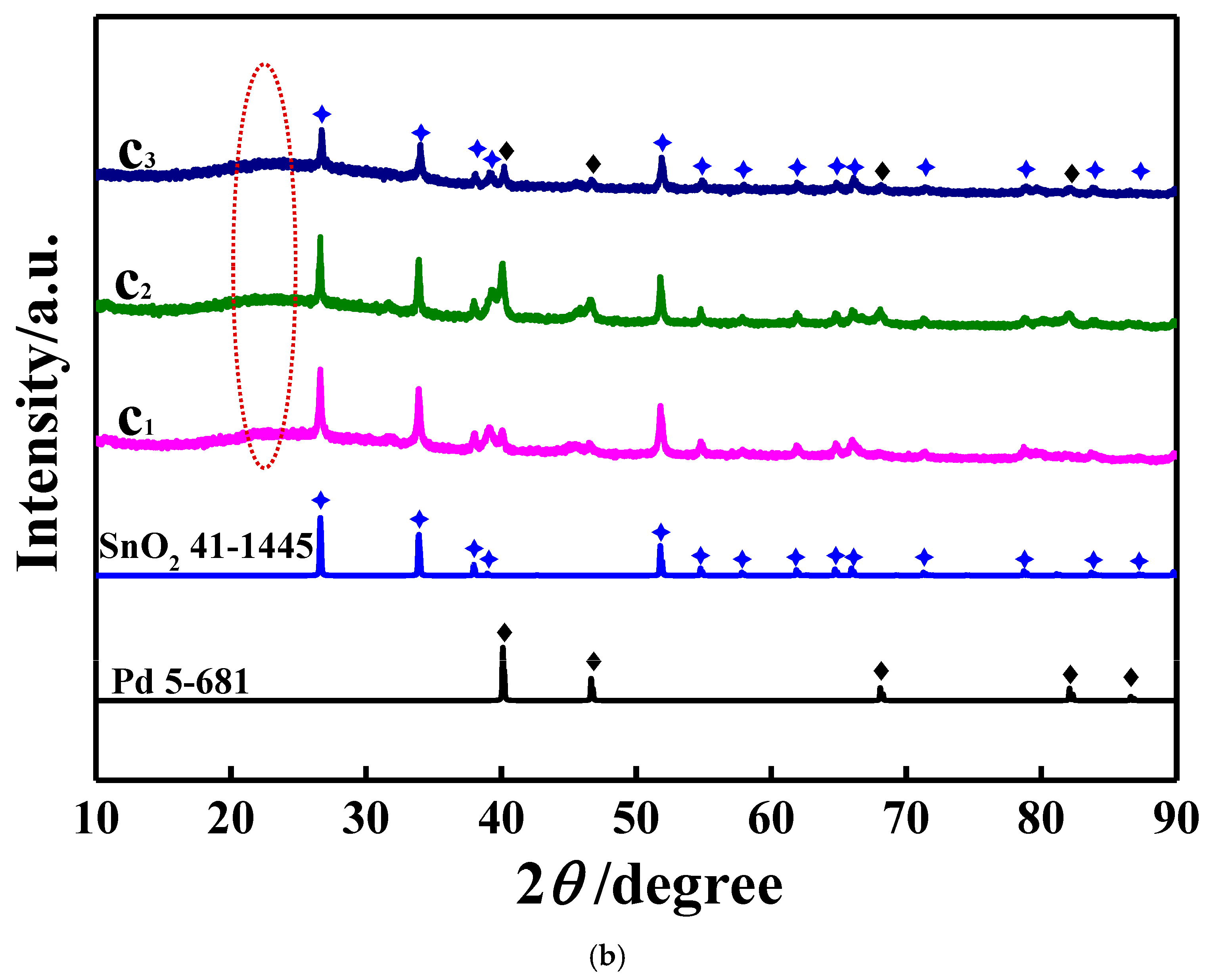
XRD patterns for all synthesized catalyst carriers are shown in Figure 1a. In this case, only the diffraction peaks assigned to SnO2 were presented in all resultant patterns; namely, the main diffraction peaks at 2θ of 26.7°, 33.9° and 51.6° were ascribed to the crystallographic planes of (110), (101) and (211) of SnO2 [29] (JCPDS, Card No. 41-1445), respectively. That is, the main crystal material of all synthesized catalyst carriers was SnO2. Apparently, the diffraction peak intensity of cc2, for example, as shown by the red circled part, the intensity of the diffraction peak at 26.7°, was higher than that of other two catalyst carriers, indicating that cc2 had the best crystallinity among all obtained catalyst carriers [30]. For the XRD patterns of all prepared catalysts (Figure 1b), except for the diffraction peaks assigned to SnO2, four diffraction peaks positioned at 39.8°, 46.7°, 68.2° and 82.2° were also clearly displayed in all resultant patterns, which matched well with the (111), (200), (220) and (311) crystallographic planes of metallic Pd (JCPDS, No. 5-681) [31], respectively, indicating the formation of metallic Pd in all resultant catalysts. Also, a diffraction peak centered at 25° (as shown by the purple circled part), which was generally ascribed to the (002) facet of graphite, was also exhibited in all resulting patterns, which substantially indicated that the resultant carbon materials were graphitized from the amorphous nature [32]. Thus, SnO2, metallic Pd and carbon materials as three main substances were contained in all synthesized catalysts.
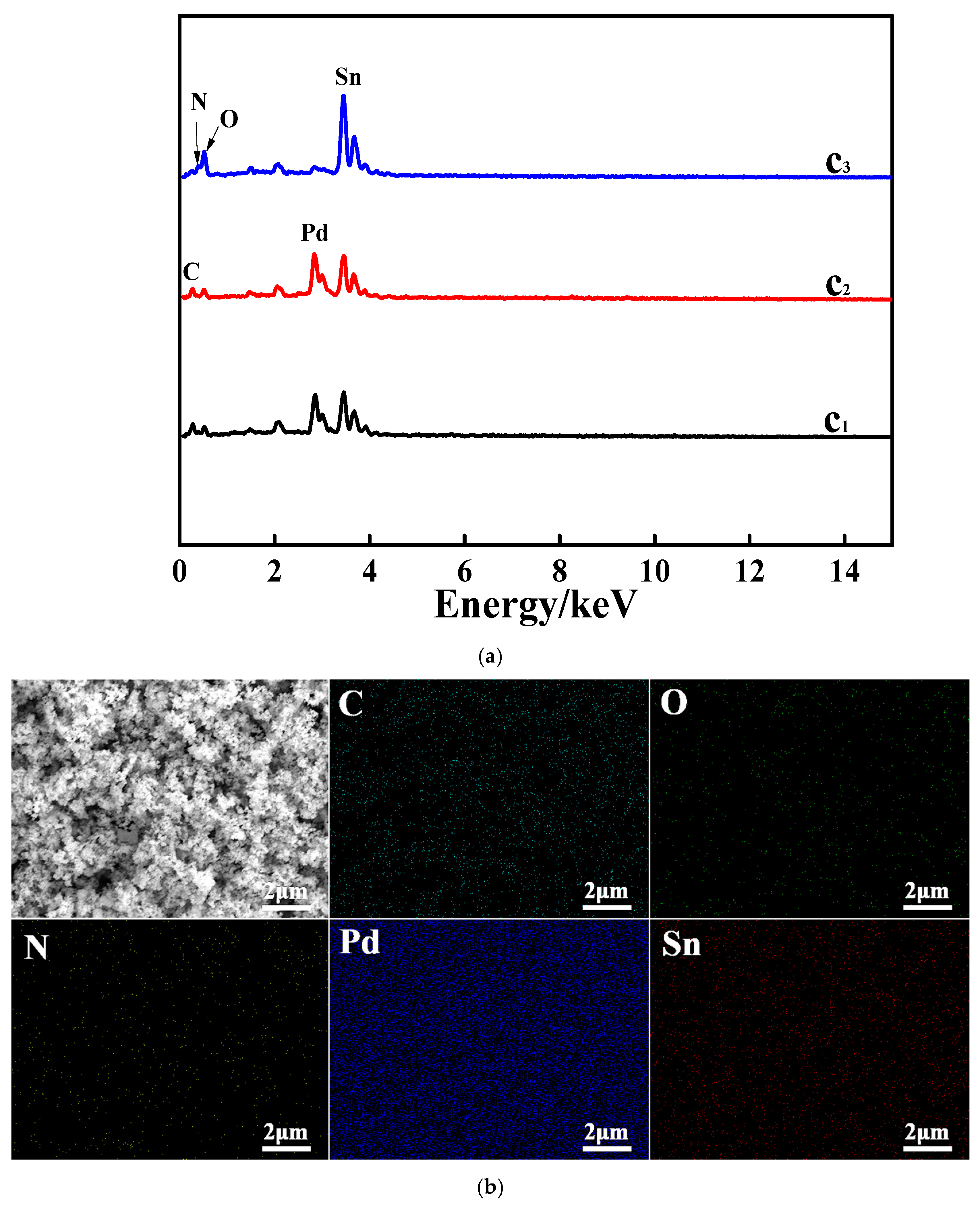
In Figure 2a, the peaks assigned to C, N, O, Pd and Sn are all clearly presented. Apparently, the presence of C was due to the existence of carbon ashes (parts of calcination products) in all produced catalysts. The atomic contents of C in catalysts c1, c2 and c3 were roughly measured to be 1.5%, 12.5% and 9.0%, respectively, indicating that the largest amount of carbon materials was contained in c2. The Pd atomic percentages were found to be 13.2% in c1, 15.0% in c2 and 1.1% in c3. Generally, the higher the atomic content of Pd, the higher the electrocatalytic activity towards the EOR. The atomic contents of Sn and O in c1, c2 and c3 were found to be 19.6% and 40.1%, 20.9% and 45.3%, and 17.5% and 58.2%, respectively. Thus, the atomic ratios of Sn to O were about 0.49, 0.46 and 0.30 for c1, c2 and c3, respectively, showing values rather smaller than 1, which strongly indicated that the prepared tin oxides should be SnO2 rather than stannous oxide (SnO). The peaks assigned to N were clearly displayed in all resultant EDS patterns, which effectively demonstrated that the element of N has been doped in all prepared catalysts. The element mappings of the above five elements of catalyst c2 are shown in Figure 2b. In each mapping, the spots representing the elements were uniformly distributed in the observation window, which substantially indicated that all the resultant substances were also dispersed homogeneously in the as-prepared catalysts.
The functional groups of all investigated catalysts were measured using FTIR, and the results are provided in Figure 3a. In each pattern, a huge and broad band at 3443 cm−1 assigned to the -OH group [33] was presented clearly, suggesting that the catalyst surfaces were fully covered by copious -OH groups, producing a surface with a relatively higher polarity. The band at 1638 cm−1 is usually attributed to the group of C=C [33], which should have originated from the formation of carbon spheres in the first hydrothermal process [33]. The band positioned at 1399 cm−1 generally stems from the C-H bending vibrations of both aldehydes and ketones [34]. That is to say, the presence of the bands at both 1638 cm−1 and 1399 cm−1 substantially indicated that carbon materials still existed in all studied catalysts. The band at about 621 cm−1 was from the presence of O-Sn-O bonds in the studied samples [35]. Therefore, the existence of carbon materials and SnO2 in all prepared catalysts was again indicated by the FTIR results.
In the Raman spectra of all prepared catalysts (Figure 3b), as illustrated by the red circled part, an evident peak representing the A1g vibration mode of SnO2 was exhibited definitely at about 634 cm−1, indicating the presence of SnO2 in all resulting catalysts [36]. In addition, two weak absorption bfigures a and bands were also displayed in all resultant patterns, especially in the pattern of c1. Generally, the peak at 1349 cm−1 (denoted as the D-band [37]) was due to the existence of carbon atoms of disorderly carbon materials, and the band appearing at 1598 cm−1 (nominated as the G-band), was ascribed to the carbon atoms with the sp2 bonds of ordered graphite [37]. Therefore, the presence of both carbon materials and SnO2 in all resultant catalysts was again affirmed by the Raman spectra results.
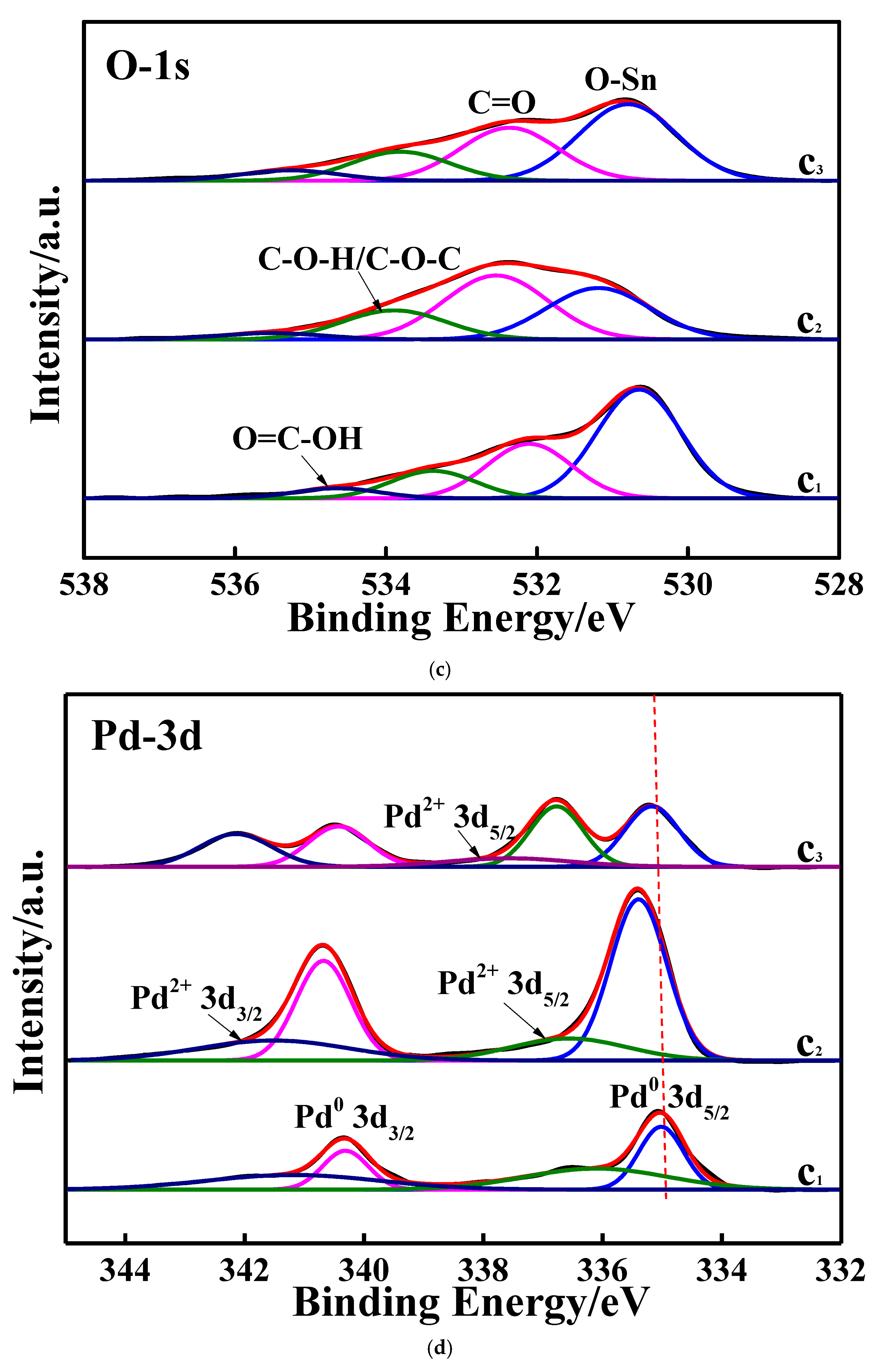
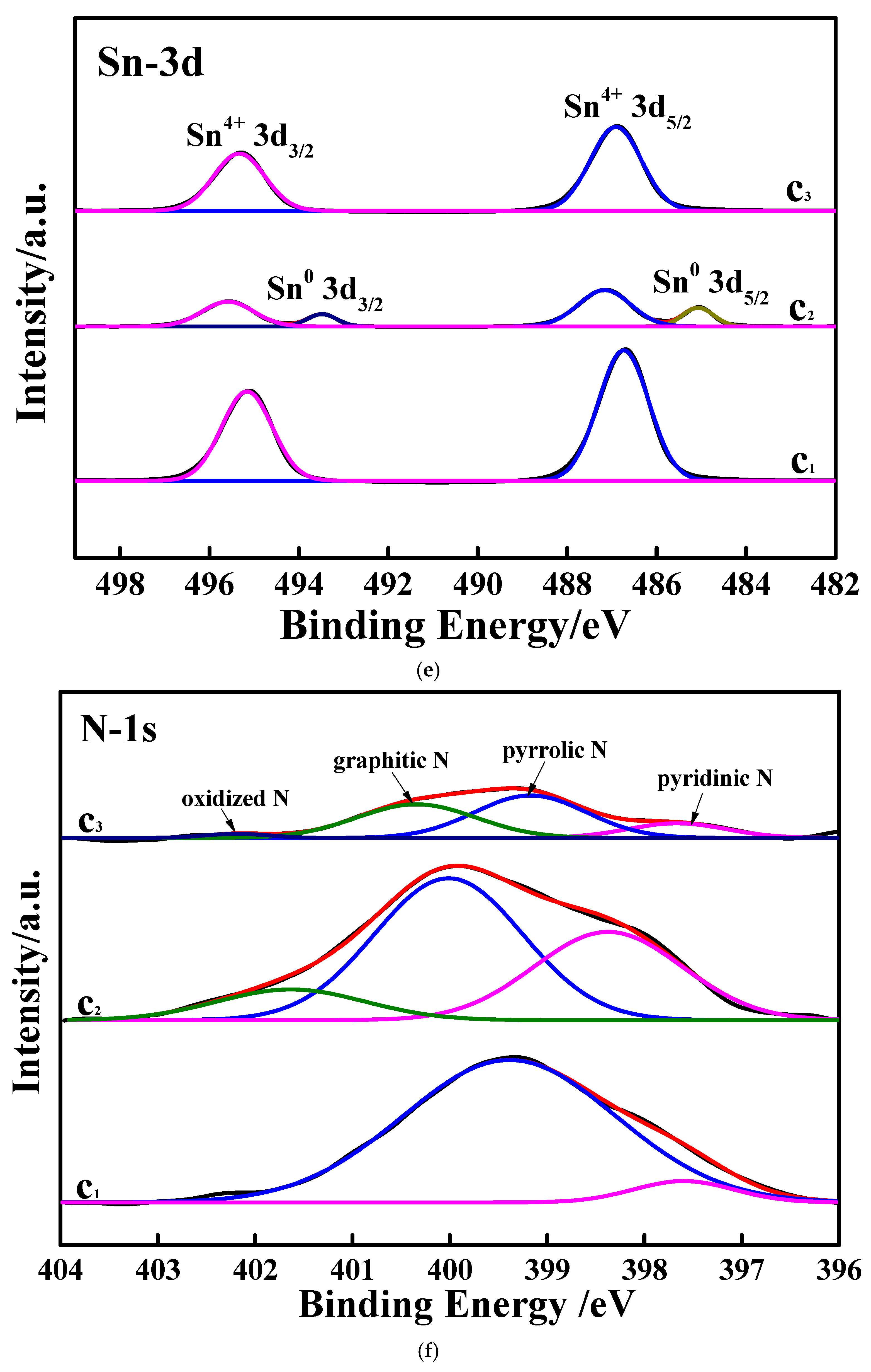
In the wide-survey XPS spectra (Figure 4a), besides the small band ascribed to N, the bands assigned to the elements of C, Pd, Sn and O were all clearly exhibited. In the patterns of the C 1s spectra (Figure 4b), a huge and broad binding energy (BE) peak was found at about 284.8 eV, which is generally indexed to the carbon atoms of sp2 C (C=C) [38]. And the BE peaks positioned at about 286.3 and 288.6 eV were ascribed to the carbon atoms of C-OH/C-N/C-O and O-C=O [39], respectively. The BE peak intensity of the peak at 284.8 eV was stronger than that of both BE peaks at about 286.3 and 288.6 eV, which effectively confirmed that the carbon materials of the resultant catalysts were mainly composed of sp2 C, which is very favorable for electronic transmission due to the formation of delocalized π bonds [40]. In the O 1s spectra (Figure 4c), four BE peaks appeared sequentially from the lower binding energy region to the higher binding energy region; namely, the BE peaks at about 530.8, 532.4, 533.9 and 534.7 eV were assigned to the O atom of O-Sn [41], C=O [42], C-O-H/C-O-C [42] and O=C-OH [43], respectively. In the Pd 3d XPS spectra (Figure 4d), the BE peaks at 335.1 eV and 340.4 eV, being indexed to Pd0 (3d5/2) and Pd0 (3d3/2), respectively, are the characteristic BE peaks of metal state of Pd [44]. Evidently, the BE peak at 335.1 eV for c1 was negatively shifted, as compared to that for c2 and c3, by 0.3 eV and 0.1 eV, respectively, indicating that the BE peaks assigned to metallic Pd for c2 had the highest binding energy among all prepared catalysts. Two other small and broad BE peaks were identified as the typical BE peaks of Pd2+; namely, the BE peaks at 336.5 eV and 341.7 eV [44] were assigned to Pd2+ (3d5/2) and Pd2+ (3d3/2), respectively, indicating that a small amount of PdO was still present in all resultant catalysts. Apparently, the peak intensity and the area of the BE peak belonging to metallic Pd, especially in the case of pattern c2, were much higher than those assigned to Pd2+, suggesting that metallic Pd was the main Pd-containing substance of all prepared catalysts. In the Sn 3d spectra (Figure 4e), only the BE peaks ascribed to Sn4+ were present in pattern c1 and pattern c3; namely, the BE peaks at 486.8 and 495.3 eV resulted from Sn4+ (3d5/2) and Sn4+ (3d3/2), respectively [41]. Thus, along with the XRD results (Figure 1b), it was again concluded that SnO2 was a main Sn-containing substance of catalysts c1 and c3. Interestingly, in the case of pattern c2, aside from the BE peaks indexed to Sn4+, the BE peaks assigned to metallic Sn were also visible; that is, the BE peaks at 485.0 and 493.5 eV stemmed from Sn0 (3d5/2) and Sn0 (3d3/2) [45], respectively, indicating that SnO2 and metallic Sn were contained in catalyst c2. In the N 1s spectra (Figure 4f), pattern c3 showed four BE peaks, namely the BE peaks at 397.6, 399.2, 400.4 and 402.2 eV assigned to pyridinic N, pyrrolic N, graphitic N and oxidized N, respectively [46]. And for catalyst c3, the atomic contents of N existing in the form of pyridinic N, pyrrolic N, graphitic N and oxidized N were measured to be about 13.8%, 45.3%, 38.3% and 2.6%, respectively. Interestingly, in pattern c2, the BE peak belonging to the oxidized N totally vanished, and the atomic contents of N existing in the form of pyridinic N, pyrrolic N and graphitic N were found to be about 33.8%, 54.4% and 11.8%, respectively. In the case of pattern c1, only two BE peaks, assigned to the N forms of pyridinic N (397.6 eV) and pyrrolic N (399.4 eV), respectively, were presented, and the atomic contents of N existing in the form of pyridinic N and pyrrolic N were found to be 6.6% and 93.4%, respectively. The above results substantially demonstrated that the element N was really doped in the prepared catalysts by forming N-containing chemical bonds. As a result, besides PdO and metallic Sn, carbon materials, metallic Pd and SnO2 were again indicated by the XPS measurement to be the main substances of all resultant catalysts, being well in accordance with the results of XRD (Figure 1b).

3.2. SEM Characterization

SEM images with different scales for the three synthesized catalysts are presented in Figure 5. For the SEM image with a 2 μm scale for catalyst c1 (image c1), a large spherical particle that was decorated with numerous flocculent particles was clearly exhibited. Interestingly, for the SEM image with a 200 nm scale of catalyst c1, no large spherical particles were observed anymore, and, instead, several destroyed spherical particles that contained many small particles (red boxed part) as well as some aggregates constructed by several small particles (blue circled part) were presented distinctly. For catalyst c2 (image c2), numerous debris-shaped particles with a hollow network structure were viewed in the SEM images (with a scale of 2 μm). In general, the hollow network structure of catalyst c2 was very beneficial to the flow of both the electrolyte solution and ethanol molecules. As shown by the yellow triangle-enclosed part of image c2 (with a scale of 200 nm), those debris-shaped particles appearing in the SEM images (with a scale of 2 μm) were piled up with a lot of small blocky particles. As for catalyst c3 (image c3), a large particle coated with many small particles was seen in the viewing window. And, as indicated by the SEM image with a scale of 200 nm, several clod-shaped particles that were formed by the accumulation of many small particles were presented clearly, which strongly affirmed that particles of catalyst c3 were also piled up with numerous small particles. The above results at least indicated that the kind of added N sources was a key factor that could directly affect the final morphologies of the catalysts prepared. Apparently, as compared to the other two catalysts, the morphology of catalyst c2 was more advantageous for electrocatalytic ability promotion due to its special empty network structure.

3.3. Electrocatalytic Performances Towards EOR Achieved by the Pd/N-C-SnO2 Catalysts

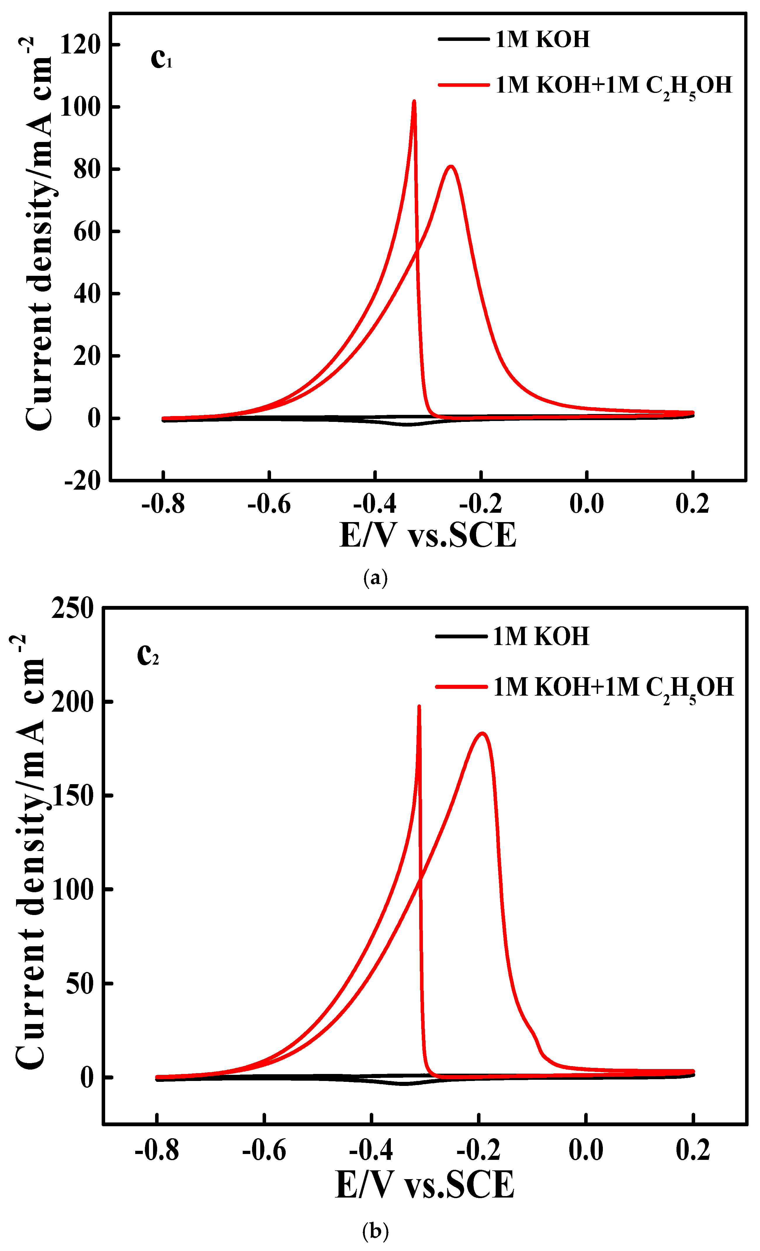
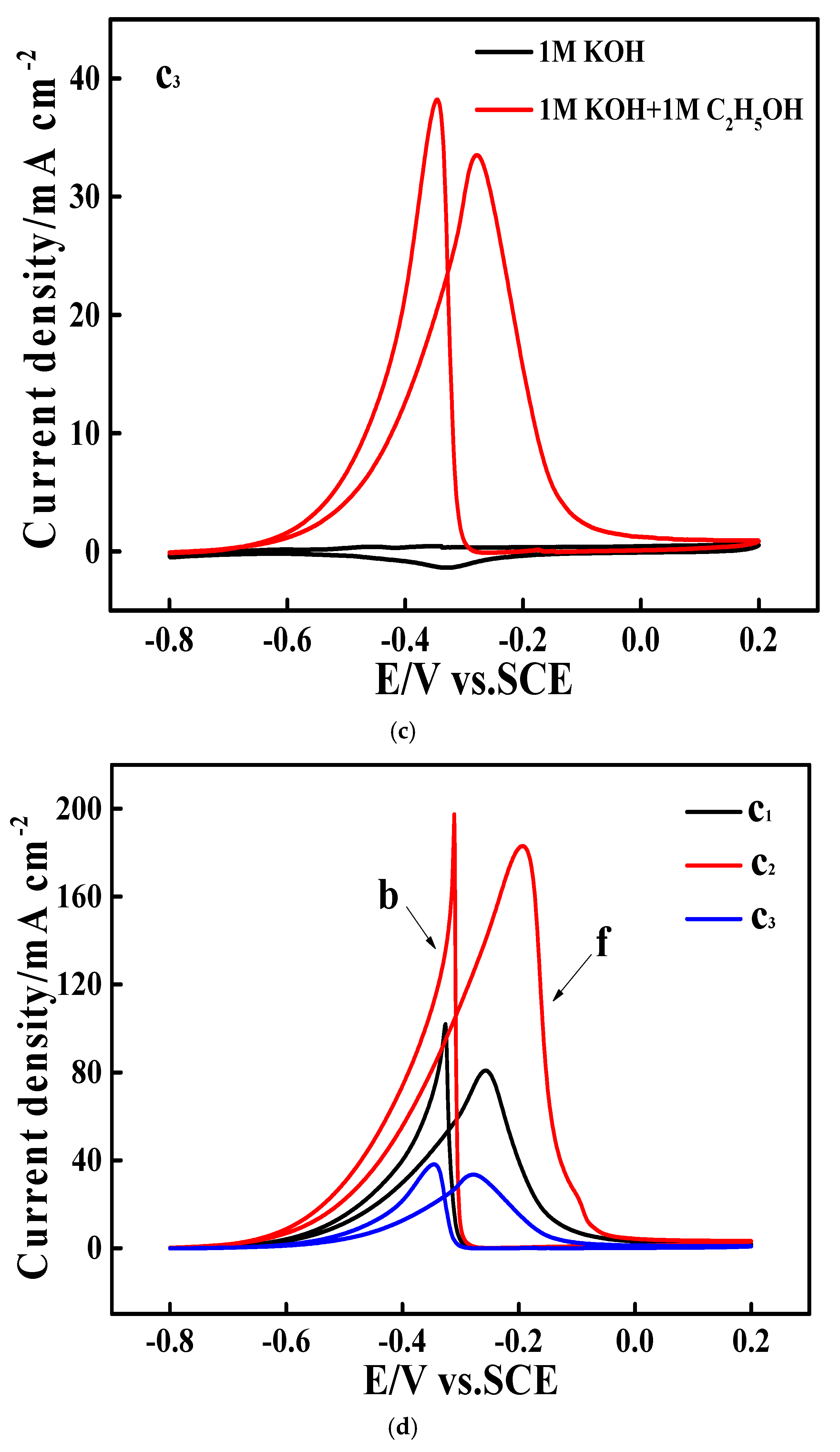
Figure 6a–c are the CV (cyclic voltammetry) curves recorded on electrodes c1, c2 and c3, respectively, in which the black and red curves were measured in solutions of 1 M KOH and 1 M KOH + 1 M ethanol, respectively. In the presence of ethanol, all the CV curves (red curves) showed two electrochemical oxidation peaks, which substantially indicated that all prepared catalysts had an electrocatalytic ability towards the EOR. Usually, the electrochemical oxidation peak resulted from the direct electrochemical oxidation of ethanol molecules (named as peak f), and the so-called abnormal electrochemical oxidation peak was due to the electrochemical oxidation of intermediates that were prepared while producing peak f [47]. All the red CV curves shown in Figure 6a–c are collected again in Figure 6d, via which the electrocatalytic abilities of all investigated catalysts towards the EOR could be well compared. Evidently, the peak current density of peak f measured on electrode c2 was about 183.7 mA cm−2, which, was about 2.24 and 5.4 times higher than that recorded on electrode c1 (81.7 mA cm−2) and c3 ( 34.2 mA cm−2), respectively. It is noteworthy that the value of 183.7 mA cm−2 was significantly higher than the state-of-the-art value of 29.3 mA cm−2 [8] reported by Huang’s group in 2022. In addition, the onset potential of the EOR on electrode c2 was about −0.63 V vs. an SCE, which was negatively shifted for about 60 mV and 110 mV compared to that of the EOR occurring on electrodes c1 and c3, respectively, implying that the EOR could proceed more easily on catalyst c2. Also, the largest CV peak area was exhibited by electrode c2 among all studied electrodes, suggesting that the largest amount of ethanol molecules was electrochemically oxidized on catalyst c2. Consequently, it was rational to conclude that catalyst c2 had the best electrocatalytic ability for the EOR.
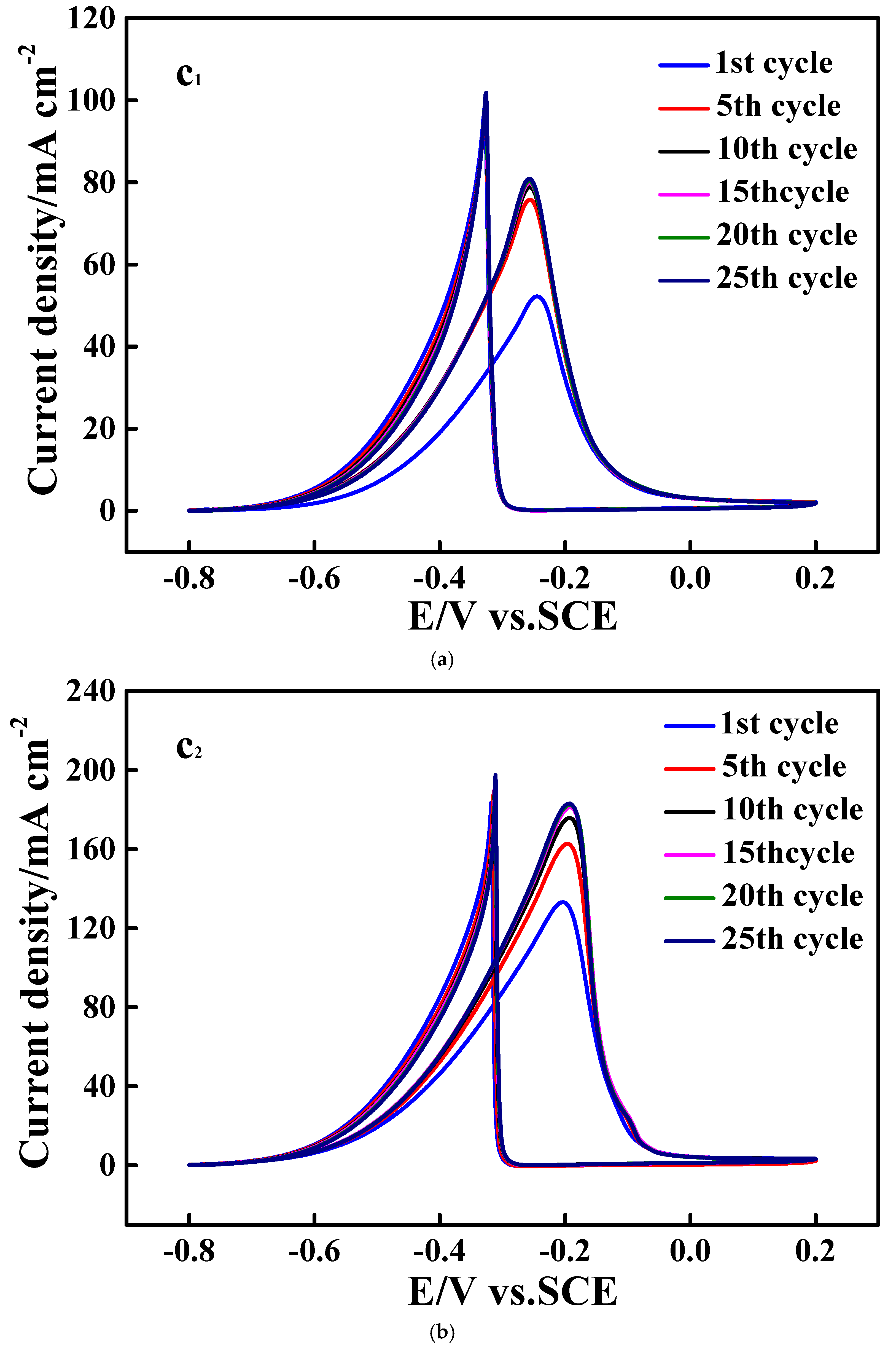
The cycling stabilities of all investigated catalysts for the EOR were evaluated by using 25 consecutive CV curves (figures of Figure 7). For the CV curves of Figure 7a–c, the peak current densities increased gradually with an increase in the cycle number in the initial stage, and after 10 cycles, relatively stable peak current density values were achieved. The relationship between the cycle number and the peak current density of peak f is summarized in Figure 7d. Apparently, electrode c2 showed the largest peak current density value in the total testing period, which strongly indicated that catalyst c2 had the best cycling stability among all examined catalysts.
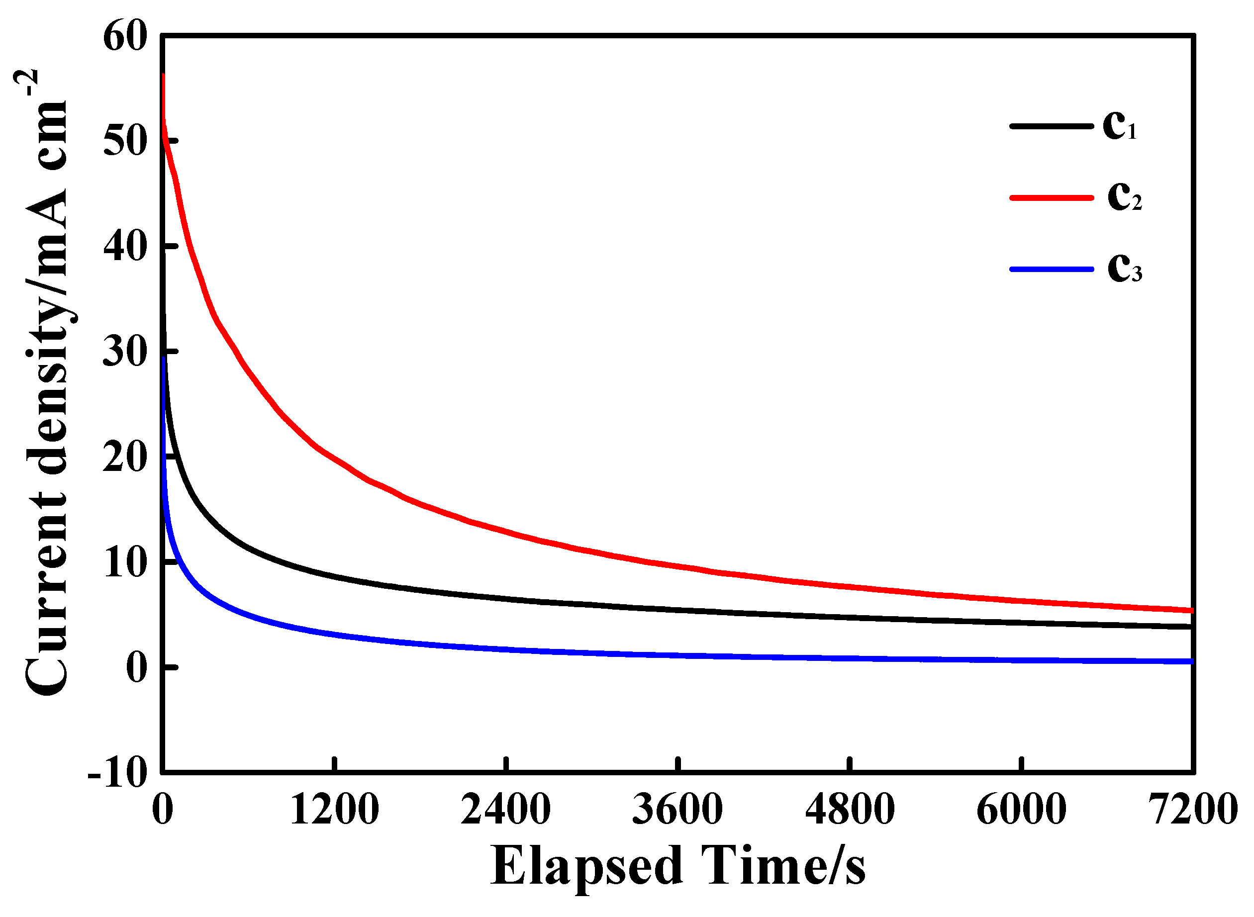
The electrocatalytic durability of all synthesized catalysts for the EOR was probed using the traditional technique of chronoamperometry (CA), and the corresponding results are given in Figure 8. In the total elapsed time of 7200 s, the largest faradaic current density was delivered by catalyst c2, for instance, at the testing time of 7200 s, the current densities were about 3.6, 5.6 and 0.5 mA cm−2 for electrodes c1, c2 and c3, respectively, exhibiting an increasing sequence of c3 ˂ c1 ˂ c2. That is, the best electrocatalytic durability was exhibited by c2 among all prepared catalysts.
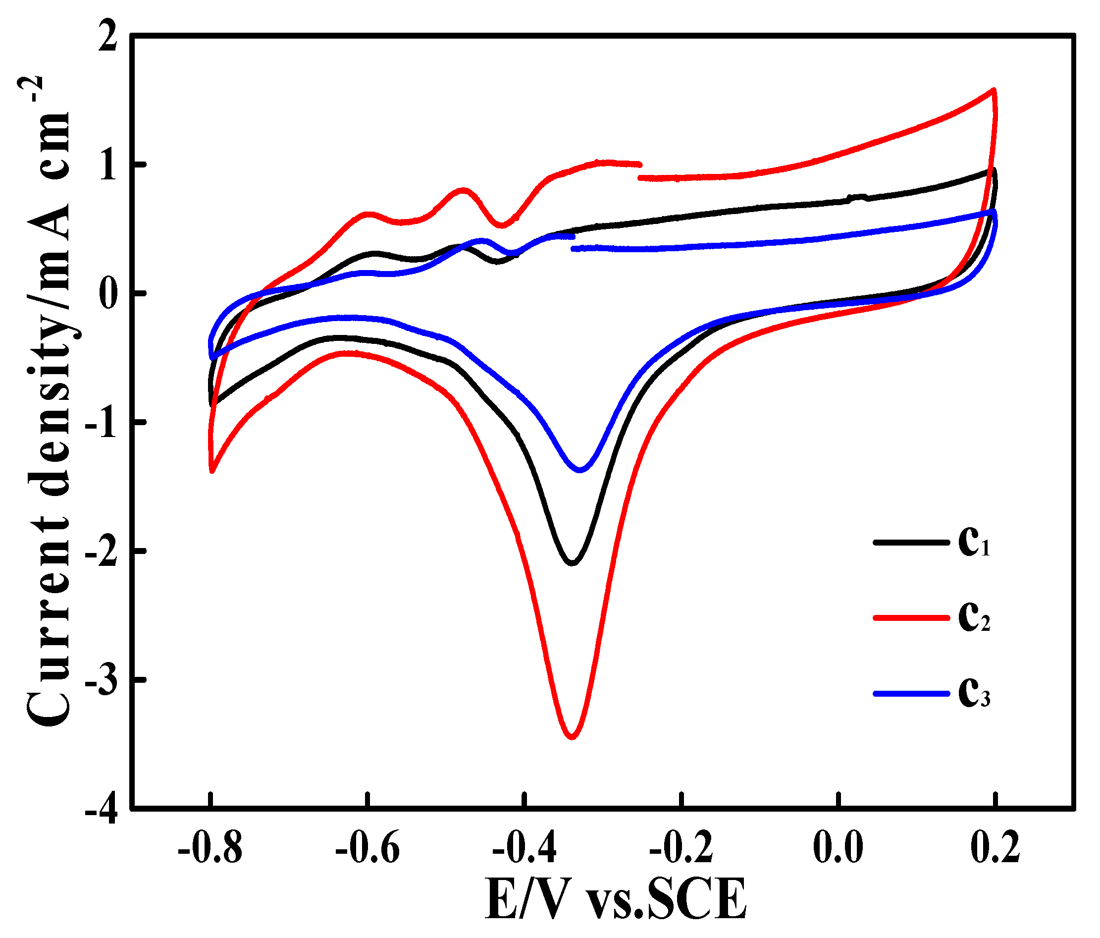
To further study the possible reasons endowing catalyst c2 with significant electrocatalytic activity, the CV curves of all prepared electrodes measured in 1 M KOH are shown in Figure 9. A large electrochemical reduction peak was observed at about −0.35 V vs. an SCE in all the CV curves, which, based on the previous work [48], should be ascribed to the electrochemical reduction of PdO to metallic Pd (for simplicity, this CV peak was denoted as CV peakPdO/Pd). That is, the shape of all the CV curves shown in Figure 9 was very close to that of the CV curve recorded on the pure Pd electrode in 1 KOH [48], which strongly proved that metallic Pd was still the major material electrocatalyzing the EOR process. Interestingly, three small electrochemical oxidation peaks appeared in all resultant CV curves, which could only be ascribed to the presence of SnO2 in all prepared catalysts. The highest peak current density of CV peak PdO/Pd and the maximum CV curve area were exhibited by electrode c2, which was well in accordance with the fact that catalyst c2 exhibited the best electrocatalytic activity among the three prepared catalysts.
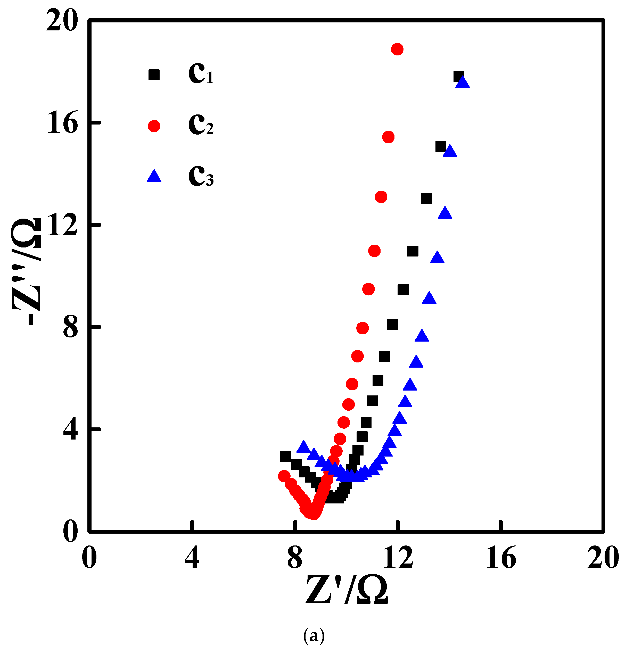
Three typical EIS plots of all examined electrodes are given in Figure 10. For the Nyquist plots of all investigated electrodes (Figure 10a), a nearly half semicircle and an almost vertical line appeared in the whole frequency region, which was very similar to the Nyquist plot of carbon-material-coated electrodes [49]. According to the previous work [50], the diameter of the semicircle was generally equal to the value of the charge transfer resistance (Rct). For the sake of simplicity, the diameter of the half semicircle was roughly equivalent to that of the semicircle; thus, the values of Rct were assessed to be about 10.1 Ω, 8.7 Ω and 11.6 Ω for electrodes c1, c2 and c3, respectively. Consequently, because of its smallest value of Rct, the fastest kinetic process was delivered by electrode c2.
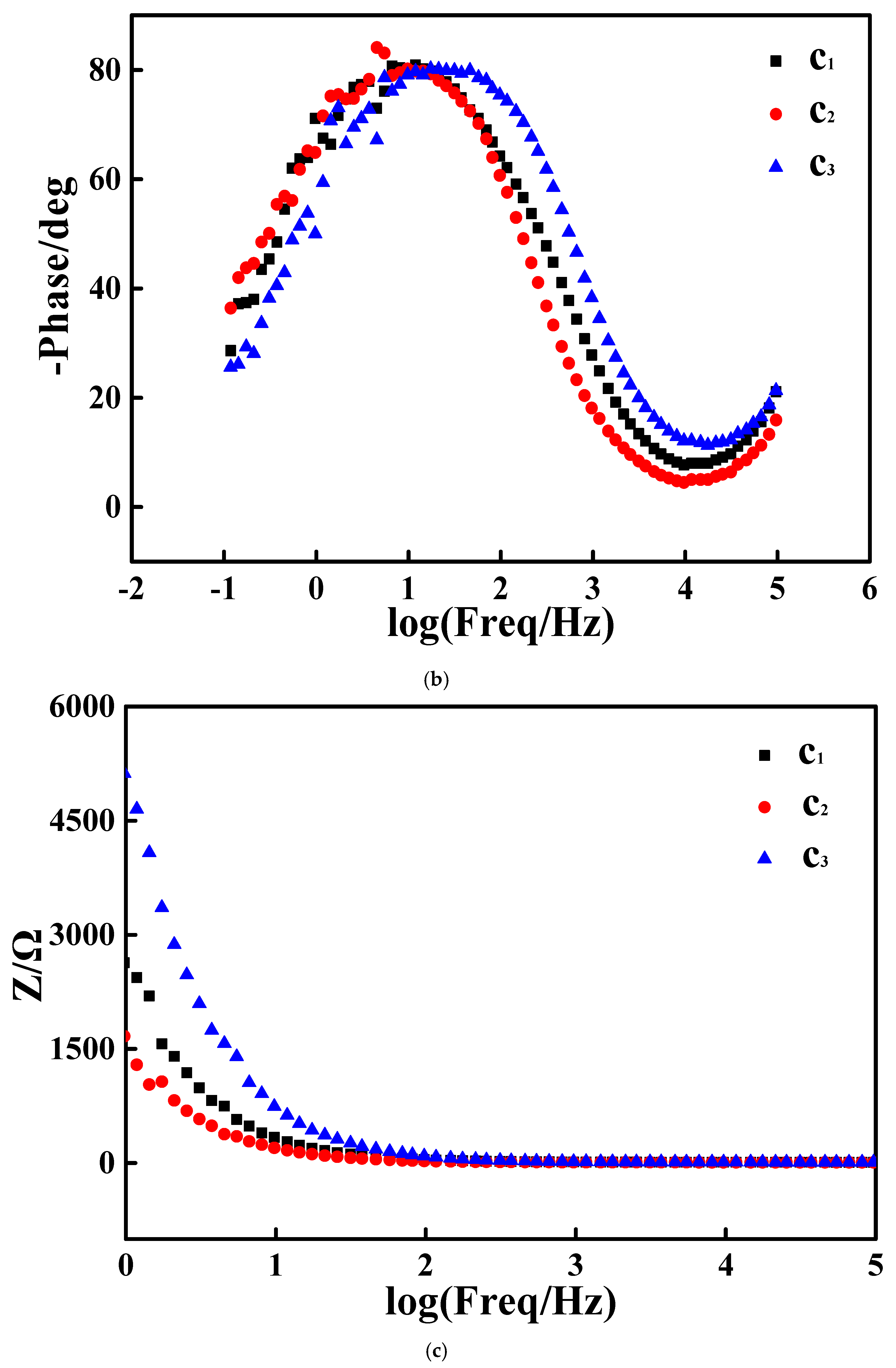
The Bode plots of all studied electrodes are given in Figure 10b, in which a well-defined symmetrical peak was exhibited in each pattern, which substantially evidenced that the main microstructures of all studied electrodes were almost identical to each other. The logf values of the symmetrical peak for electrodes c1 and c2 were identical, namely logf = 1, and the logf value of the symmetrical peak for electrode c3 was about 1.5, which suggested that the capacitance values simulated from Bode plots of both c1 and c2 were larger than that fitted from the Bode plot of c3 [51]. In other words, the microstructure of both c1 and c2 was looser than that of c3, being well in accordance with the SEM observation results (Figure 5).
The relationship between the applied frequency and the values of the total resistance (Rtotal) for all studied electrodes is shown in Figure 10c. When the used frequency was 1 Hz, the values of Rtotal for electrodes c1, c2 and c3 were approximately equal to 2652 Ω, 1685 Ω and 5122 Ω, respectively, displaying an increasing sequence of c2 ˂ c1 ˂ c3. This Rtotal value sequence was well maintained in the frequency region ranging from 1 to 30 Hz. Interestingly, as the frequency was higher than 30 Hz, almost identical values of Rtotal were exhibited by all studied electrodes. Summarily, electrode c2 delivered the smallest value of Rtotal, which was thought to be a main reason enabling c2 to possess the optimal electrocatalytic ability towards the EOR among all studied catalysts.
In summary, the special network structure, the higher content of metallic Pd and the larger CV curve area were considered to be the major causes giving c2 the best EOR electrocatalytic activity among all prepared catalysts. The development of a novel method for preparing N- and C-present SnO2 catalyst carriers and the preparation of a N- and C-present SnO2-supported Pd-based catalyst showing noticeable electrocatalytic ability for the EOR were evaluated as the main contributions of this preliminary work.

4. Conclusions

In this work, nitrogen- and carbon-present tin dioxide-supported Pd composite catalysts (denoted as Pd/N-C-SnO2) were prepared using an HCH method, in which three N sources were employed in preparing the N-C-SnO2 catalyst carriers. The existence of carbon materials, SnO2 and metallic Pd in all resultant catalysts was substantially indicated by the XRD and XPS results. As indicated by the SEM images, being rather different from catalysts c1 and c3, catalyst c2 showed a hollow network structure. Above all things, as demonstrated by the conventional techniques of CV and CA, all resultant catalysts delivered an electrocatalytic activity for the EOR. Among three resulting catalysts, catalyst c2 showed the best electrocatalytic activity towards the EOR, which was analyzed to mainly result from the empty network structure and higher content of metallic Pd. Showing the preparation of Pd/N-C-SnO2 catalysts as well as their excellent electrocatalytic activities for the EOR was the main dedication of this preliminary work. In particular, due to its special morphology and significant electrocatalytic activity towards the EOR, catalyst c2 was considered as a potential catalyst for the EOR.

Author Contributions

Writing-original draft, Conceptualization, K.D.; Investigation, W.L.; Data curation, M.L. and M.D. and Y.B. and X.L.; Resources, H.W. All authors have read and agreed to the published version of the manuscript.

Funding

This research was funded by the Hebei Natural Science Foundation (B2024205035) and Innovation Ability Improvement Project of Hebei province (225A4402D) and The Innovation Capability Improvement Plan Project of Hebei Province (22567604H).

Informed Consent Statement

Informed consent was obtained from all subjects involved in the study.

Data Availability Statement

All data included in this study are available upon request by contact with the corresponding author.

Acknowledgments

The work was financially supported by the Hebei Natural Science Foundation (B2024205035), the Innovation Ability Improvement Project of Hebei Province (225A4402D) and the Innovation Capability Improvement Plan Project of Hebei Province (22567604H).

Conflicts of Interest

Author Hui Wang and Keqiang Ding was employed by the company Hebei LingDian New Energy Technology Ltd. Co. The remaining authors declare that the research was conducted in the absence of any commercial or financial relationships that could be construed as a potential conflict of interest.

References

  1. Wei, K.; Lin, H.; Zhao, X.; Zhao, Z.; Marinkovic, N.; Morales, M.; Huang, Z.; Perlmutter, L.; Guan, H.; Harris, C.; et al. Au/Pt bimetallic nanowires with stepped Pt sites for enhanced C-C cleavage in C2+ alcohol electro-oxidation reactions. J. Am. Chem. Soc. 2023, 145, 19076–19085. [Google Scholar] [CrossRef] [PubMed]
  2. Chen, W.; Luo, S.; Sun, M.; Wu, X.; Zhou, Y.; Liao, Y.; Tang, M.; Fan, X.; Huang, B.; Quan, Z. High-entropy intermetallic PtRhBiSnSb nanoplates for highly efficient alcohol oxidation electrocatalysis. Adv. Mater. 2022, 34, 2206276. [Google Scholar] [CrossRef] [PubMed]
  3. Yan, W.; Li, G.; Cui, S.; Park, G.-S.; Oh, R.; Chen, W.; Cheng, X.; Zhang, J.-M.; Li, W.; Ji, L.-F.; et al. Ga-modification near-surface composition of Pt−Ga/C catalyst facilitates high-efficiency electrochemical ethanol oxidation through a C2 intermediate. J. Am. Chem. Soc. 2023, 145, 17220–17231. [Google Scholar] [CrossRef] [PubMed]
  4. Xu, B.; Liu, T.; Liang, X.; Dou, W.; Geng, H.; Yu, Z.; Li, Y.; Zhang, Y.; Shao, Q.; Fan, J.; et al. Pd-Sb rhombohedra with an unconventional rhombohedral phase as a trifunctional electrocatalyst. Adv. Mater. 2022, 34, 2206528. [Google Scholar] [CrossRef]
  5. Ao, W.; Ren, H.; Cheng, C.; Fan, Z.; Yin, P.; Qin, Q.; Zhang, Q.; Dai, L. Mesoporous PtPb nanosheets as efficient electrocatalysts for hydrogen evolution and ethanol oxidation. Angew. Chem. Int. Ed. 2023, 62, e202305158. [Google Scholar] [CrossRef]
  6. Wang, Y.; Zheng, M.; Li, Y.; Ye, C.; Chen, J.; Ye, J.; Zhang, Q.; Li, J.; Zhou, Z.; Fu, X.-Z.; et al. p-d orbital hybridization induced by a monodispersed Ga site on a Pt3Mn nanocatalyst boosts ethanol electrooxidation. Angew. Chem. Int. Ed. 2022, 61, e202115735. [Google Scholar] [CrossRef]
  7. Zhu, L.D.; Zhao, T.S.; Xu, J.B.; Liang, Z.X. Preparation and characterization of carbon-supported sub-monolayer palladium decorated gold nanoparticles for the electro-oxidation of ethanol in alkaline media. J. Power Sources 2009, 187, 80–84. [Google Scholar] [CrossRef]
  8. Zhang, Y.; Liu, X.Z.; Liu, T.Y.; Ma, X.Y.; Feng, Y.G.; Xu, B.Y.; Cai, W.B.; Li, Y.F.; Su, D.; Shao, Q.; et al. Rhombohedral Pd-Sb nanoplates with Pd-terminated surface: An efficient bifunctional fuel-cell catalyst. Adv. Mater. 2022, 34, 2202333. [Google Scholar] [CrossRef]
  9. Antoniassi, R.M.; Erikson, H.; Solla-Gullón, J.; Torresi, R.M.; Feliu, J.M. Formic acid electrooxidation on small, {1 0 0} structured, and Pd decorated carbon-supported Pt nanoparticles. J. Catal. 2021, 400, 140–147. [Google Scholar] [CrossRef]
  10. Baruah, S.; Kumar, A.; Peela, N.R. Role of ZSM-5/AC hybrid support on the catalytic activity of Pd-Ag electrocatalysts towards ethanol oxidation: An experimental and kinetic study. Electrochim. Acta 2023, 453, 142357. [Google Scholar] [CrossRef]
  11. Bai, G.; Yang, X.; Jia, S.; Lv, Y.; Tong, X. Controlling the size of Ag@Pd catalysts to boost ethanol oxidation. J. Electron. Mater. 2023, 52, 3841–3847. [Google Scholar] [CrossRef]
  12. Chen, M.; Zhang, S.; Zhu, C.; Zhang, H.; Zhu, L.; Feng, Y.; Wang, J.; Yang, Q.; Liu, B.; Xu, W. Pyrolysis of ZIF-8 to PdZn alloy nanoparticles on carbon doping with nitrogen for highly efficient electrocatalytic alcohol oxidation. J. Alloys Compd. 2023, 965, 171281. [Google Scholar] [CrossRef]
  13. Alfonso, A.N.R.; Villanueva, M.L.; Laxamana, J.R.P.; Necesito, H.G.G.; Tongol, B.J.V. Enhanced electrocatalytic activity of palladium electrocatalysts supported on corncob biochar for ethanol oxidation reaction in alkaline medium. J. Chin. Chem. Soc. 2024, 71, 324–332. [Google Scholar] [CrossRef]
  14. Yu, K.; Lin, Y.; Fan, J.; Li, Q.; Shi, P.; Xu, Q.; Min, Y. Ternary N, S, and P-doped hollow carbon spheres derived from polyphosphazene as Pd supports for ethanol oxidation reaction. Catalysts 2019, 9, 114. [Google Scholar] [CrossRef]
  15. Wu, B.; Meng, H.; Morales, D.M.; Zeng, F.; Zhu, J.; Wang, B.; Risch, M.; Xu, Z.J.; Petit, T. Nitrogen-rich carbonaceous materials for advanced oxygen electrocatalysis: Synthesis, characterization, and activity of nitrogen sites. Adv. Funct. Mater. 2022, 32, 2204137. [Google Scholar] [CrossRef]
  16. Xiao, S.; Zhu, L.; Osman, S.M.; Feng, Y.; Zhang, S.; Li, G.; Zeng, S.; Luque, R.; Chen, B.H. Ultrahigh stable covalent organic framework-derived carbon-nitrogen-supported palladium nanoparticles for highly efficient electrocatalytic methanol and ethanol oxidation reactions. Green Chem. 2022, 24, 5813–5821. [Google Scholar] [CrossRef]
  17. Su, Y.; Li, C.; Xu, L.; Xue, J.; Yuan, W.; Yao, C.; Liu, J.; Cheng, M.; Hou, S. Palladium nanoparticles supported on flower-like boron, nitrogen doped carbon for electrochemical oxidation ethanol reaction. J. Alloys Compd. 2022, 901, 163333. [Google Scholar] [CrossRef]
  18. Li, S.; Wu, L.; Zhao, J.; Li, R.; Yang, H.; Zhao, L.; Jin, R. Nitrogen-doped carbon nanotubes embedded with nitrogen-doped carbon black anchoring Pd nanocrystals to boost ethanol electrooxidation. Green Chem. 2023, 25, 10033–10042. [Google Scholar] [CrossRef]
  19. Zheng, X.; Wang, N.; Zhao, Y.; Wu, Y.; Wang, X.; Zhao, Y. Nanosized Pd-loaded the Fe3C encapsulated by N-doped carbon nanotube as an electrocatalyst for oxygen reduction and ethanol oxidation reactions. Appl. Surf. Sci. 2022, 595, 153512. [Google Scholar] [CrossRef]
  20. Shekhawat, A.; Samanta, R.; Panigrahy, S.; Barman, S. Electrocatalytic oxidation of urea and ethanol on two-dimensional amorphous nickel oxide encapsulated on N-doped carbon nanosheets. ACS Appl. Energy Mater. 2023, 6, 3135–3146. [Google Scholar] [CrossRef]
  21. Quílez-Bermejo, J.; Morallon, E.; Cazorla-Amoros, D. On the deactivation of N-doped carbon materials active sites during oxygen reduction reaction. Carbon 2022, 189, 548–560. [Google Scholar] [CrossRef]
  22. Yang, M.M.; Kong, Q.Q.; Feng, W.; Yao, W.T. N/O double-doped biomass hard carbon material realizes fast and stable potassium ion storage. Carbon 2021, 176, 71–82. [Google Scholar] [CrossRef]
  23. Jongsomjit, S.; Prapainainar, P.; Sombatmankhong, K. Synthesis and characterisation of Pd-Ni-Sn electrocatalyst for use in direct ethanol fuel cells. Solid State Ion. 2016, 288, 147–153. [Google Scholar] [CrossRef]
  24. Li, Q.Y.; Zhou, X.X.; Lu, M.N.; Pan, S.Q.; Ajmal, S.; Xiang, D.; Sun, Z.J.; Zhu, M.Z.; Li, P. In-situ synthesis of carbon-supported ultrafine trimetallic PdSnAg nanoparticles for highly efficient alcohols electrocatalysis. J. Colloid Interface Sci. 2024, 653, 1264–1271. [Google Scholar] [CrossRef]
  25. Nan, L.; Fan, Z.; Yue, W.; Dong, Q.; Zhu, L.; Yang, L.; Fan, L. Graphene-based porous carbon-Pd/SnO2 nanocomposites with enhanced electrocatalytic activity and durability for methanol oxidation. J. Mater. Chem. A 2016, 4, 8898–8904. [Google Scholar] [CrossRef]
  26. Pinheiro, V.S.; Souza, F.M.; Gentil, T.C.; Nascimento, A.N.; Bὃhnstedt, P.; Parreira, L.S.; Paz, E.C.; Hammer, P.; Sairre, M.I.; Batista, B.L.; et al. Sn-containing electrocatalysts with a reduced amount of palladium for alkaline direct ethanol fuel cell applications. Renew. Energy 2020, 158, 49–63. [Google Scholar] [CrossRef]
  27. Gao, Q.; Mou, T.; Liu, S.; Johnson, G.; Han, X.; Yan, Z.; Ji, M.; He, Q.; Zhang, S.; Xin, H.; et al. Monodisperse PdSn/SnOx core/shell nanoparticles with superior electrocatalytic ethanol oxidation performance. J. Mater. Chem. A 2020, 8, 20931–20938. [Google Scholar] [CrossRef]
  28. Wang, X.; Zhang, C.; Chi, M.; Wei, M.; Dong, X.; Zhu, A.; Zhang, Q.; Liu, Q. Two-dimensional PdSn/TiO2-GO towards ethanol electrooxidation catalyst with high stability. Int. J. Hydrogen Energy 2021, 46, 19129–19139. [Google Scholar] [CrossRef]
  29. Pinheiro, V.S.; Souza, F.M.; Gentil, T.C.; Nascimento, A.N.; Parreira, L.S.; Hammer, P.; Sairre, M.I.; Batista, B.L.; Santos, M.C. Electrocatalysts based on low amounts of palladium combined with tin nanoparticles and cerium dioxide nanorods for application as ADEFC anodes. Int. J. Hydrogen Energy 2021, 46, 39438–39456. [Google Scholar] [CrossRef]
  30. Ding, K.; Gu, H.; Zheng, C.; Liu, L.; Liu, L.; Yan, X.; Guo, Z. Octagonal prism shaped lithium iron phosphate composite particlesas positive electrode materials for rechargeable lithium-ion battery. Electrochim. Acta 2014, 146, 585–590. [Google Scholar] [CrossRef]
  31. Li, Y.; Yao, L.; Zhang, L.-Q.; Liu, A.-R.; Zhang, Y.-J.; Liu, S.-Q. Palladium nanoparticles supported on nitrogen-doped carbon spheres as enhanced catalyst for ethanol electro-oxidation. J. Electroanal. Chem. 2014, 730, 65–68. [Google Scholar] [CrossRef]
  32. Wu, J.; Jin, C.; Yang, Z.; Tian, J.; Yang, R. Synthesis of phosphorus-doped carbon hollow spheres as efficient metal-free electrocatalysts for oxygen reduction. Carbon 2015, 82, 562–571. [Google Scholar] [CrossRef]
  33. Sun, X.; Li, Y. Colloidal carbon spheres and their core/shell structures with noble-metal nanoparticles. Angew. Chem. Int. Ed. 2004, 43, 597–601. [Google Scholar] [CrossRef] [PubMed]
  34. Priya, P.S.D.; Philip, A.; Kumar, A.R. An investigation on the compositional effects of 3D graphite on theelectrochemical performance of NiO-Co3O4 composite. Diam. Relat. Mater. 2024, 141, 110597. [Google Scholar]
  35. Yadav, V.; Singh, N.; Meena, D. Investigation of structural and optical properties of pure SnO2, ZnO and SnO2/ZnO composite nanorods. Mater. Today Proc. 2022, 62, 3368–3375. [Google Scholar] [CrossRef]
  36. Sambasivam, S.; Obaidat, I.M. Effect of iron doping on ESR and Raman spectra of SnO2 nanomaterials. Mater. Today Proc. 2020, 28, 587–590. [Google Scholar] [CrossRef]
  37. Farithkhan, A.; John, S.A. Investigation of biomass-derived heteroatom-doped carbon fiber aerogel decorated with NiCo2S4 flowers as a binder-free anode for urea electrooxidation: From a sustainable standpoint. ACS Appl. Eng. Mater. 2023, 1, 458–468. [Google Scholar] [CrossRef]
  38. Wang, Y.; Xu, G.; Xue, C.; Zhang, C.; Xue, J.; Zhang, X. Self-nitrogen-doped hierarchical porous carbon spheres as metal-free catalyst for efficient photocatalytic CO2 reduction. Sep. Purif. Technol. 2024, 342, 127008. [Google Scholar] [CrossRef]
  39. Zhang, C.; Wang, Y.; Zhang, X.; Dong, Z.; Wu, W.; Fan, C. Self-nitrogen-doped carbon spheres assisted CeO2 composites as a bifunctional adsorbent/photocatalyst for CO2 photoreduction. Fuel 2024, 362, 130848. [Google Scholar] [CrossRef]
  40. Liu, H.; Zhu, S.; Cui, Z.; Li, Z.; Wu, S.; Liang, Y. Tuning the π-electron delocalization degree of mesoporous carbon for hydrogen peroxide electrochemical generation. J. Catal. 2020, 392, 1–7. [Google Scholar] [CrossRef]
  41. Babu, B.; Reddy, I.N.; Yoo, K.; Kim, D.; Shim, J. Bandgap tuning and XPS study of SnO2 quantum dots. Mater. Lett. 2018, 221, 211–215. [Google Scholar] [CrossRef]
  42. Selepe, C.T.; Gwebu, S.S.; Matthews, T.; Mashola, T.A.; Sikeyi, L.L.; Zikhali, M.; Mbokazi, S.P.; Makhunga, T.S.; Adegoke, K.A.; Maxakato, N.W. Electro-catalytic properties of palladium and palladium alloy electro-catalysts supported on carbon nanofibers for electro-oxidation of methanol and ethanol in alkaline medium. Catalysts 2022, 12, 608. [Google Scholar] [CrossRef]
  43. Sabzehmeidani, M.M.; Kazemzad, M.; Ebadzadeh, T. Bimetallic Au-Pd nanoparticles decorated electrospun spinel CoFe2O4 nanostructures as efficient electrocatalysts for ethanol fuel oxidation in alkaline media. Int. J. Hydrogen Energy 2024, 51, 517–528. [Google Scholar] [CrossRef]
  44. Song, T.; Gao, F.; Zhang, Y.; Yu, P.; Wang, C.; Shiraishi, Y.; Li, S.; Wang, C.; Guo, J.; Du, Y. Shape-controlled PdSn alloy as superior electrocatalysts for alcohol oxidation reactions. J. Taiwan Inst. Chem. Eng. 2019, 101, 167–176. [Google Scholar] [CrossRef]
  45. Chellasamy, V.; Thangadurai, P. Design, synthesis and investigations of PdxSn1−x nanoparticle-impregnated NiTiO3 as highly active electrocatalyst for methanol oxidation reaction in alkaline medium. J. Mater. Sci. 2023, 58, 2721–2739. [Google Scholar] [CrossRef]
  46. Song, X.; Chen, X.; Chen, W.; Ao, T. Fe-N/C anode with pseudocapacitive behavior derived from Fe-modified ZIF-8/C composites for phosphorus capture. Colloids Surf. A 2023, 673, 131867. [Google Scholar] [CrossRef]
  47. Ding, K.; Wang, Y.; Yang, H.; Zheng, C.; Cao, Y.; Wei, H.; Wang, Y.; Guo, Z. Electrocatalytic activity of multi-walled carbon nanotubes-supported PtxPdy catalysts prepared by a pyrolysis process toward ethanol oxidation reaction. Electrochim. Acta 2013, 100, 147–156. [Google Scholar] [CrossRef]
  48. Liang, Z.X.; Zhao, T.S.; Xu, J.B.; Zhu, L.D. Mechanism study of the ethanol oxidation reaction on palladium in alkaline media. Electrochim. Acta 2009, 54, 2203–2208. [Google Scholar] [CrossRef]
  49. Ding, K.; Zhao, Y.; Liu, L.; Li, Y.; Liu, L.; Wang, Y.; Gu, H.; Wei, H.; Guo, Z. Multi-walled carbon nanotubes supported Pd composite nanoparticles hydrothermally produced from technical grade PdO precursor. Electrochim. Acta 2015, 176, 1256–1265. [Google Scholar] [CrossRef]
  50. Ding, K.; Li, B.; Shi, F.; Di, M.; Yan, M.; Xu, L.; Wang, X.; Wang, H. A palladium and nickel composite catalyst composed of huge spherical particles and sawdust-shaped particles showing significant electrocatalytic activities towards ethanol oxidation reaction (EOR). Int. J. Electrochem. Sci. 2022, 17, 220639. [Google Scholar] [CrossRef]
  51. Xu, Y.; Wang, S.; Peng, H.; Yang, Z.; Martin, D.J.; Bund, A.; Nanjundan, A.K.; Yamauchi, Y. The interphase electrochemical characteristics of the cobaltosic oxide in organic electrolyte by bode plots: Double layer capacitance and pseudocapacitance. ChemElectroChem 2019, 6, 2456–2463. [Google Scholar] [CrossRef]
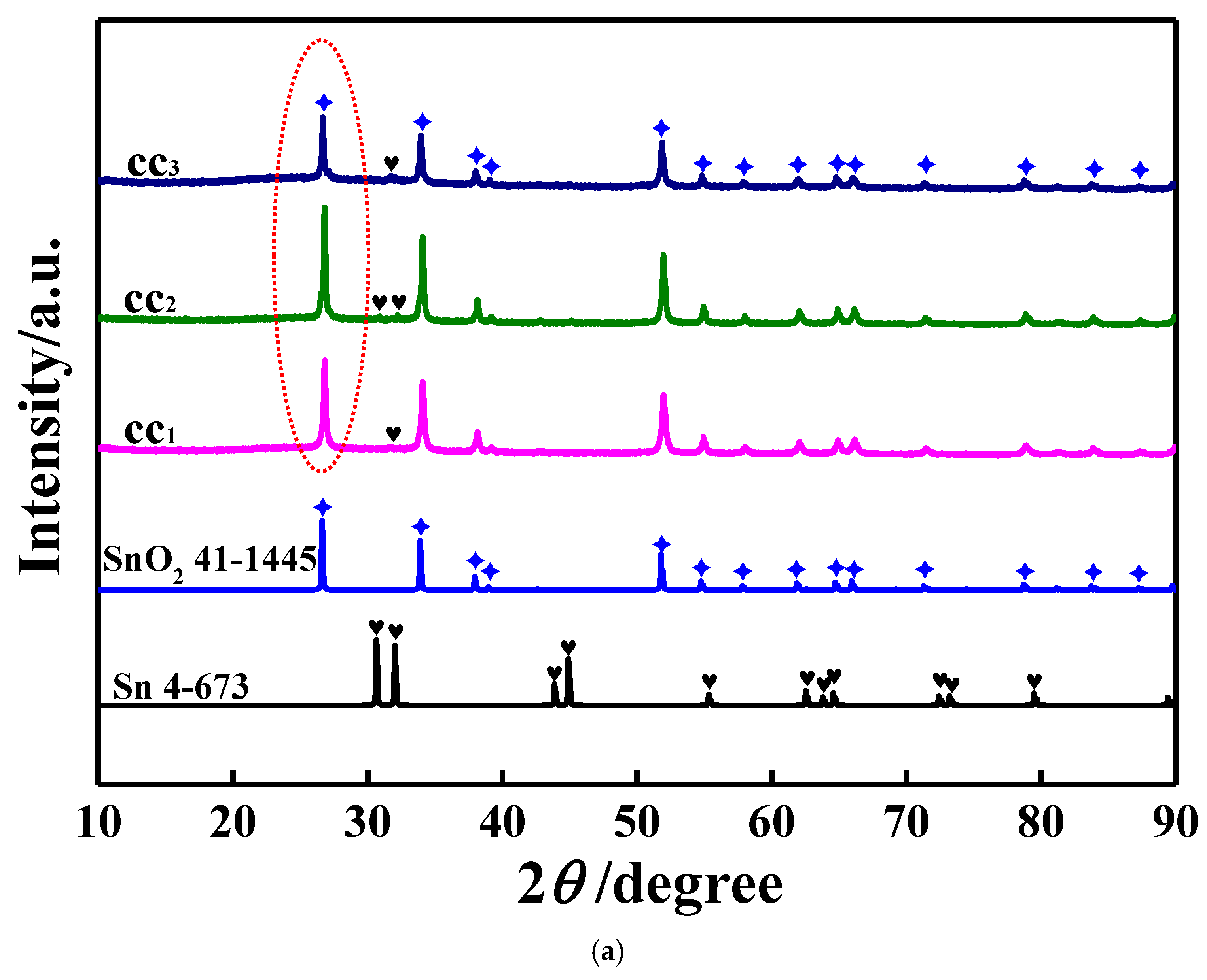
Figure 1. (a) XRD patterns of all catalyst carriers in which the standard XRD patterns for both SnO2 and metallic Sn are also presented. Patterns cc1, cc2 and cc3 correspond to catalyst carriers cc1, cc2 and cc3, respectively. (b) XRD patterns for three prepared catalysts, where the standard XRD patterns for SnO2 and metallic Pd are also illustrated. Patterns c1, c2 and c3 correspond to catalysts c1, c2 and c33, respectively.
Electrochem 05 00032 g001aElectrochem 05 00032 g001b
Figure 2. (a) EDS patterns of all prepared catalysts. Patterns c1, c2 and c3 correspond to catalyst c1, c2 and c33, respectively. (b) EDS mappings of C, N, O, Pd and Sn for catalyst c2.
Electrochem 05 00032 g002
Figure 3. (a) FTIR spectra of all resultant catalysts. (b) Raman spectra for all prepared catalysts. In (a,b), patterns c1, c2 and c3 correspond to catalysts c1, c2 and c3, respectively.
Electrochem 05 00032 g003
Figure 4. XPS spectra for the resultant catalysts. (a) Wide scan XPS survey spectra; (b) high resolution XPS spectra of C 1s; (c) high resolution XPS spectra of O 1s; (d) high resolution XPS spectra of Pd 3d; (e) high resolution XPS spectra of Sn 3d; (f) high resolution XPS spectra of N 1s. In above figures, pattern c1, c2 and c3 were the patterns of catalyst c1, c2 and c3, respectively.
Electrochem 05 00032 g004aElectrochem 05 00032 g004bElectrochem 05 00032 g004c
Figure 5. SEM images for three prepared catalysts. The scale bars of SEM images were respectively 2 μm and 200 nm. Image c1, c2 and c3 were the images of catalyst c1, c2 and c3.
Electrochem 05 00032 g005
Figure 6. CV (cyclic voltammetry) plots recorded on all prepared electrodes at 50 mV s−1, in which the black and red curve were respectively recorded in 1M KOH and a solution of 1M KOH + 1M ethanol. (ac) were respectively measured using electrode c1, c2 and c3. Above CV curves measured on various electrodes at 50 mV s−1 in a solution of 1M KOH + 1M ethanol are collected in (d).
Electrochem 05 00032 g006aElectrochem 05 00032 g006b
Figure 7. Successive CV curves measured at a scan rate of 50 mV s−1 in a solution of 1M KOH + 1M ethanol, in which (ac) were respectively plotted employing electrode c1, c2 and c3, and in each figure, CV curves were successively recorded at the 1st, 5th, 10th, 15th, 20th and 25th cycles. For all above successive CV curves, the relationship between the peak f current density and the cycling number was again summarized in (d), in which curve c1, c2 and c3 were respectively recorded using electrode c1, c2 and c3.
Electrochem 05 00032 g007aElectrochem 05 00032 g007b
Figure 8. The CA (Chronoamperometry) curves recorded in a solution of 1M KOH + 1M ethanol, the working potential was fixed at −0.27 V vs. SCE. Curve c1, c2 and c3 were respectively recorded using electrode c1, c2 and c3.
Electrochem 05 00032 g008
Figure 9. CV curves of various catalyst-coated GC electrodes measured in 1M KOH at 50 mV s−1. Curves c1, c2 and c3 correspond to the cases of using electrodes c1, c2 and c3, respectively.
Electrochem 05 00032 g009
Figure 10. EIS (electrochemical impedance spectroscopy) measurement results for various catalyst-coated GC electrodes measured in an electrolyte solution containing 1M KOH and 1M ethanol. In each figure, curves c1, c2 and c3 correspond to the cases of using electrodes c1, c2 and c3, respectively. (a) Nyquist plots; (b) Bode plots; (c) curves showing the relationship between the total impedance (Z) and the applied frequency.
Electrochem 05 00032 g010aElectrochem 05 00032 g010b
Disclaimer/Publisher’s Note: The statements, opinions and data contained in all publications are solely those of the individual author(s) and contributor(s) and not of MDPI and/or the editor(s). MDPI and/or the editor(s) disclaim responsibility for any injury to people or property resulting from any ideas, methods, instructions or products referred to in the content.