Article

Influence of the Precoat Layer on the Filtration Properties and Regeneration Quality of Backwashing Filters

Karlsruhe Institute of Technology (KIT), Strasse am Forum 8, 76131 Karlsruhe, Germany
*
Authors to whom correspondence should be addressed.
Eng 2021, 2(2), 181-196; https://doi.org/10.3390/eng2020012
Submission received: 2 April 2021 / Revised: 17 May 2021 / Accepted: 17 May 2021 / Published: 21 May 2021

Abstract

:
For solid–liquid separation, filter meshes are still used across large areas today, as they offer a cost-effective alternative, for example, compared to membranes. However, particle interaction leads to a continuous blocking of the pores, which lowers the flow rate of the mesh and reduces its lifetime. This can be remedied by filter aids. In precoat filtration, these provide an already fully formed filter cake on the fabric, which acts as a surface and depth filter. This prevents interaction of the particles to be separated with the mesh and thus increases the service life of the mesh. In this work, the influence of a precoat layer with different fibre lengths of cellulose on the filtration behavior is investigated. A satin with a pore size of 11 µm is used as the filter medium. The effects of the precoat layer on the filter media resistance, the filter cake resistance, the turbidity impact, and the regenerability of the fabrics are investigated. This study shows an overview of the suitability of various cellulose fibres based on different aspects as filter aids for particles in ultrafine filtration.

1. Introduction

For filtration of suspensions with fine particulate solids through filter cloth, it is necessary, due to the high pressure drop of such aggregates, to carry out filtration at low filter cake thicknesses or high filtration pressures. In these cases, an economical filtrate volume flow is ensured. In the macroscopic description of the filtration process according to the filter equation (Equation (1)), the filtration pressure Δp is described as a function of the sum of the filter cake resistance α H · H F C and filter mean resistance R F M . Furthermore, the dynamic viscosity η f , the filtrate volume flow V ˙ F , and the filter area A represent variables that influence the filtration pressure Δp. As in the macroscopic, the microscopic process of particle separation in and on the meshes of the filter fabric is decisive for the quality of the filtration. If the mesh of the fabric is larger than the diameter of the particle system to be filtered, particle penetration (turbidity blow) occurs, and the quality of the filtrate suffers as a result [1]. The more unbalanced the ratio in the direction of “large mesh, fine particles”, the more pronounced the turbidity impact. In the worst case, no filtration takes place at all and no filter cake is formed on the mesh.
Δ p = α H · H F C + R F M · η f · V ˙ F A
One possible option for improving filtration is to replace the filter fabric with a finer woven mesh. This is also recommended in view of the large amounts of particle penetration in the filtrate. Scientific studies already provide good reference values as to which meshes are suitable for the filtration of a wide variety of particle systems [2,3,4,5]. Furthermore, the choice of mesh is often based on practical experience and the know-how of the equipment operators, manufacturers, and mesh suppliers. According to [6], the mesh selection is characterized independently of manufacturers as a function of mesh size, particle size distribution, and particle shape. These are based on experiments with the pressurized filter cell, a reliable instrument for selecting suitable meshes [7]. Satin fabrics in particular have a smooth surface due to their weave and are advantageous for applications with backwashing and clogging behaviour. However, they have a comparatively higher filter medium resistance, which is why it is a trade-off between high filter resistance and advantageous backwashing. Therefore, tests are necessary for the individual case [8]. In addition to selecting a more suitable mesh, the addition of filter aids is also an option. These aids form a “particle protection layer” directly on the filter mesh, thus allowing more extensive filtration of the particle system [9,10]. The particles are then deposited on the surface of the filter aid and in its porous structure.
In this paper, the influence of filter aids during filtration is investigated in more detail. For this purpose, three filter aids are investigated and their effect on filtration with three selected particle systems is described according to [8,11]. This is done on a selected number of fabrics according to [6]. In addition to the effect of a precoat layer on the filtration, an analysis of the regeneration behavior in the backwashing filtration is also carried out. For this purpose, a flow reversal of the filtrate stream occurs, which detaches the filter cake together with the precoat layer from the tissue and throws it off. This is done in a liquid environment according to [8]. The results of these investigations can be applied in the filtration of fine particle systems with filter aids, including subsequent regeneration.

2. Theory

The use of filter aids for filtering liquids is a widespread field of application and can be found, for example, in the clarification of beer and wine (food industry), but also in the chemical industry [12]. The effect of the precoat layer and the objective are always identical: the addition of a further particle system with a different particle size distribution facilitates filtration because the looser structure of this added particle structure leads to improved separation of finer particles. In the application, a distinction is made between two possible types of filter aid addition. These are shown schematically in Figure 1.
In bodyfeed filtration, the filter aid is added to the suspension stream upstream of the filter. Here, the particle system has time to interact with the filter aid. The filter aid usually has a structure with a large surface-to-volume ratio where the particles of the suspension can adhere to it. The mixed flow of the filter aid and particle system now reaches the filter and ideally forms a lower specific cake resistance than the pure particle system. Studies on particle mixtures have shown that the specific cake resistance of fine particle systems can be reduced in this way [13]. In addition, fewer to no particles should pass through the mesh in the form of turbidity. The hydraulic load of the filtration and the quality of the filtrate are thus increased. The second application concept is regular precoat filtration. For this, a filter cake of precoat material is first built up on the fabric of the filter. In terms of equipment, a separate feed tank is required for this. The suspension then flows through this layer of precoat and the particles contained within it separate on and in the precoat cake. The turbidity shock at the beginning of filtration should be prevented by this process. In the context of this study, the focus is on filtration using precoat layers.
Precoat filtration, also known as precoat filtration, corresponds to simple cake filtration. Here, the applied cake of the precoat material serves as a filter medium for the subsequent cake filtration. Compared to a simple filter with pure surface filtration, a cake also has a depth filtration effect [14]. This also enables filtration of the finest particles down to 0.1 µm [15,16]. The filter fabric serves only as a base for the cake and can have correspondingly larger mesh sizes [1]. The main difference with simple cake filtration lies in the composition of the filter cake, which consists of several components. The composition consequently changes with continuous filtration time, as more and more components of the suspension adhere to the cake because of penetration. The precoat filter cake should be as open-pored as possible to prevent clogging of the filter cake and to keep the pressure loss across the cake low. Often, filter aids are added to the suspension to be filtered as body feed, which also makes the further cake structure as open-pored as possible, which also has a positive effect on cleaning [17,18].
In most cases, the precoat filter cake consists of a primary layer and a secondary layer. The task of the primary layer is to bridge the large pores of the filter fabric and guarantee the load-bearing capacity of the cake. It is important that the permeability remains as low as possible, since the primary layer does not have an actual filtration effect but leads to an increase in the initial resistance through interaction with the filter fabric [6]. Usually, this consists of a coarse material with a diameter larger than the pore size. The second layer contains a much larger proportion of finer particles, creating a distinct pore system responsible for the actual filtration task [12].
The selection and quantity of additives are mostly based on experience and are therefore mostly not the optimum. This is difficult to predict because it is based on complex systems and includes many variables such as material, particle-size-distribution (PSD), and concentration. In this context, many studies have investigated the amount of body feed to produce the most optimal filter cake with an open-pore structure. In this context, initial studies presented models of the dependence of the filter cake resistance on the filter aid and assumed that solid–liquid separation occurs only at the surface of the cake, which means that an open-pored cake would not be necessary at all. More recent research, however, shows the emphasized role of the depth effect of the filter cake. Here, the importance of a detailed characterization of the precoat layer to improve the filtration performance becomes clear [17].

3. Methodology

The methodical procedure of this elaboration is essentially based on three test series:
  • Pressure groove tests according to [7] to determine the specific cake resistance and filter medium resistance;
  • Gravimetric turbidity measurement by filtration of the filtrate from the pressure groove using a membrane;
  • Backwash system according to [11] for filtration and regeneration (cake discharge).
As a standard experimental device for determining filtration characteristics, the pressurized filter cell is an essential tool for determining the specific cake resistance of the particle systems and filter aids, as well as the filter medium resistance. In all experiments, a concentration of 0.05 kg∙L−1 and a filtrate volume of 200 mL are used, with an effective filtration pressure of 1 bar. According to [16], the resulting specific precoat quantity of 2.5 kg∙m−2 ensures sufficient bridging in the precoat. Furthermore, in all tests of the pressure groove, the fabric is used only once to create the same starting conditions in all tests. Therefore, aging phenomena do not occur. The filtrate produced by the pressurized filter cell is subjected to further filtration through a membrane with a pore diameter of 0.4 µm, which is measured gravimetrically beforehand. A further determination of the membrane weight following the filtration conveys the mass of residual particles in the filtrate after the filter mesh. This procedure makes it possible to characterize the filter effect of the fabric and filter aid and to make statements about the quality of the filtration and follows a procedure with reference to [7].
Following [11], filtration is also carried out on a backflush filter system, which is illustrated in Figure 2. At the beginning of the experiment, two storage tanks are to be set up. One container is for the particle system to be filtered, while the second contains the filter aid. In both cases, care must be taken to ensure enough dispersion and possible swelling in the fluid. Following the sample preparation, the test is carried out. For this purpose, the precoat material is first fed into the process chamber and a defined quantity is built up on the filter fabric (I). The cake thickness is mainly controlled by the amount of filtrate and the concentration in the receiver tank. After a defined filtrate volume has been reached, displacement of the suspension of filter medium by clear water occurs (II). This step enables the filter cake thickness to be compared with the concentration of the filter aid in the receiver tank and the amount of filtrate that has passed through. In addition, this allows a clear cut between the precoat and particle filter cake. Once this is done, filtration starts again, but now with the particle system (I). In this case, too, a defined filtrate volume and filtrate concentration control the desired cake thickness. Subsequently, the cake is again displaced by clear water (II) to optically determine the cake thickness. By comparing both images, it is possible to define the precoat layer and particle layer. After complete displacement of the particle suspension, the filter is regenerated by backwashing with cake discharge (III). For this purpose, the backwashing fluid (deionized water) flows through the filter fabric against the direction of the filtrate, dissolves the built-up filter cake, and allows it to slide off. The cake then consolidates at the bottom of the vessel and can be discharged before the test is repeated (IV).

4. Materials

Based on the experimental procedure described in the “Methodology”, the experimental matrix is carried out using the particle systems of [6,7] with the precoat material shown in Figure 3 and a satin fabric with a mesh size of 11 µm (Sefar AG, Heiden, Switzerland). A mesh size of 11 µm is chosen because this corresponds to the mean diameter x 50 , 3 of the particles. This ensures that one part of the particles is rejected on surface and the other part is to be separated via bridging. Due to the scope, reference is made to the publications just mentioned for a description of the particle systems. The filter aids are described in the following section. Three precoat materials Arbocel-NV00, Filtracel and Vitacel (J. Rettenmaier & Söhne GmbH + Co KG, Rosenberg, Germany), which are shown in Figure 3, are the subject of this study.
Precoat C1, with the manufacturer’s designation Arbocel-NV00, it is a fibrous filter aid made of cellulose. A laser diffraction measurement yields a value of 87.0 µm as the average fibre length. Filtration tests with the pressure groove have shown a specific cake resistance of 1.7 × 10¹¹ m−2. Related to the mean fibre length with power 1011, the Carman-Kozeny order of magnitude is plausible.
The next filter aid is Filtracel (C2) with a mean particle diameter of x 50 , 3   = 127.9 µm. The measured cake resistivity is 1.9 × 10¹² m−2 and is larger than that of C1 and C3. This behavior is contrary to expectations, since cellulose C2 is the coarser filter aid after laser diffraction and thus should yield a more porous filter cake. However, Figure 3 also shows a higher particle size distribution for Precoat C2, which may be a reason for the more compact cake.
The last Precoat material, Vitacel (C3), represents the highest clarity in the food industry. This can also be seen from the particle size in Figure 3, as this cellulose is very fine, short fibres with a mean diameter of 16.7 µm. Regarding the filtration properties, this filter aid has a specific cake resistance of 8.5 × 10¹¹ m−2. This value is analogous to C1 below C2, which means that a different cake forming behavior can be assumed. All three filter aids undergo the experimental procedure described in the “Methodology” to validate the filtration and regeneration properties of the filter. This is described in the following chapter.

5. Interpretation

In this chapter, the test evaluation and interpretation will now take place based on the test materials presented in the chapter “Material” and the test procedure described in the chapter “Methodology”. For this purpose, the tests are divided up and described separately based on the results from the pressure groove and backflush filtration. The following chapter, “Conclusion”, contains a summary with an outlook.

5.1. Influence of a Precoat Layer on the Filter Resistance

Within the scope of the filtration tests, the filter medium resistances and the filter cake resistances during filtration with filter aids are to be investigated. For this purpose, the filter aids C1, C2, and C3 presented in the “Material” and particle systems made of [6] are each filtered and measured with the 11 µm satin fabric in the pressure groove. This is followed by the determination of the resistances for the combinations of all filter aids and the particle systems. First, a precoat layer is washed onto the filter cloth and then the suspension with the particles to be filtered is passed over the precoat.
The filter mean resistances of the resulting series of measurements are shown in Figure 4. The use of C1 results in the lowest filter mean resistances overall. C2 with the longest fibre length produces resistances with the highest values. This could be explained with the long fibres which have a higher possibility for deformation. In addition, C2 has a wider particle size distribution, making the filter cake more compact. C3, with the smallest fibre length, has a correspondingly low cake porosity due to its small average diameter, which increases the resistance. Therefore, the particle size of cellulose is less important compared to the size distribution and deformability of the cellulose fibres in this range of 17 µm to 128 µm. For the particle systems, all three are in the same order of magnitude and can be considered identical with respect to the deviation. The difference from the values published in [6] is due to the use of new tissues in each of the experiments reported here. This shows that particles are deposited differently in the tissue. Since new fabrics were always used here, there were no irreversible particle inclusions that affect the resistance. As a result, the resistance depends only on the particle size and not on the shape. The difference in shape only causes particles to embed themselves differently in the fabric and thus change the resistance during continuous tests. When several layers are combined, i.e., a precoat layer and a particle layer, the precoat represents the new filter medium. Depending on the precoat, the respective filter cake or new filter medium has a different porosity. The particle system P1 shows the clearest interaction, since the values of the filter medium resistance increase the most here. In contrast, almost no difference can be seen between P2 and P3. P1 thus penetrates much further into the filter cake and significantly increases the resistance. The orthorhombic shape consequently favors penetration into the tissue, while flaky and acicular particles are more likely to be deposited on the surface.
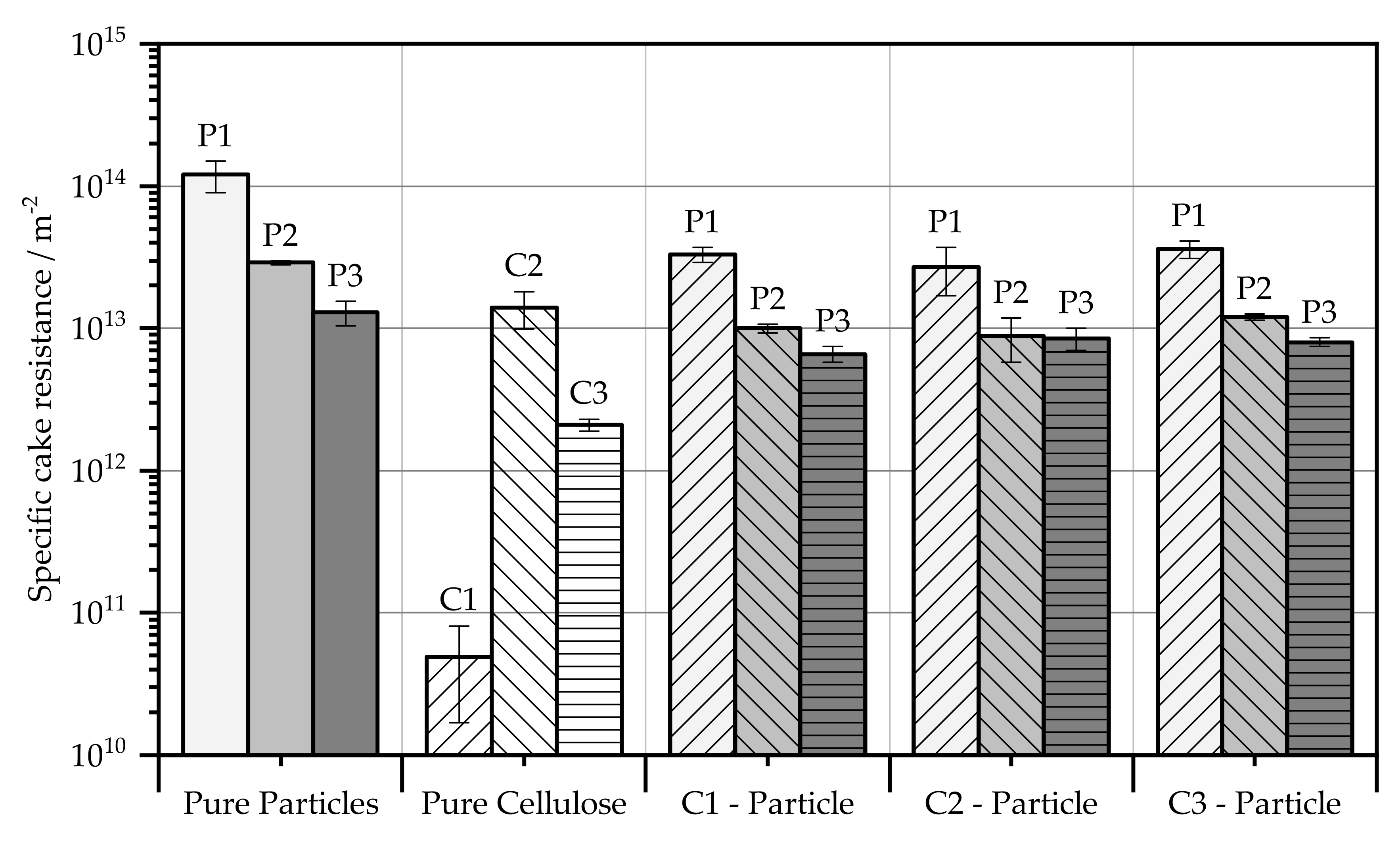
In addition to the filter medium resistances, the filter cake resistances show a resistance value independent of the precoat presented in Figure 5. While with the precoat the filter cake resistances still show differences in the range of 103, when the deviation is considered, no difference can be seen in the resistances after the particle layer has been applied. The particle systems thus dominate the resistance value, which means that there is practically no dependence of the filter cake resistance on the cellulose type. Overall, however, the filter cake resistance has decreased compared to that of the pure particle systems, which is positive for the pressure drop.

5.2. Influence of Filter Aids on the Turbidity Impact

Another possibility for validating a precoat layer is the turbidity impact that occurs. As a rule, this occurs at the beginning of a filtration process until enough solid bridges have formed on the mesh. These solid bridges prevent further solid passage through the filter fabric. When a precoat layer is used, these solid bridges are already formed, reducing solid passage.
The turbidity impact was determined by the individual particle systems, filter aid, and the combination of all particles with the filter aid. Figure 6 shows the mass of residual particles per filtrate volume of all cellulose fibres used as a pure stock and precoat material. A comparison of the cellulose fibres shows a decreasing trend from C1 to C3. C1 produces the highest turbidity of 8.3 mg L−1 compared to the other cellulose fibres, whereas this value is halved for C2 and is only 1.3 mg L−1 for C3. The number of particles passing through the filter is thus a factor of 6.5 higher with cellulose C1 than when C3 is used. This is not as expected since C3 has a much smaller mean diameter than C1. One explanation is that due to the higher filter cake resistance of C3, i.e., 8.2 × 10¹¹ m−2 compared to C1 with 1.7 × 10¹¹ m−2, the smaller pore size within the cake retains more particles. C2, at 7.2 × 10¹¹ m−2, lies between the other two fibres and confirms the trend due to the turbidity that occurs.
Besides the cellulose fibres, the turbidity due to filtration of the particulate systems is higher. The peak occurs with the orthorhombic P1, i.e., 24.1 mg L−1, and is the same order of magnitude with the acicular P2. Only P3, which is acicular, is characterized by a low turbidity impact of 3.7 mg L−1. Surface deposition according to [19] can be seen here. The long fibres settled on the filter and prevent further penetration of particles. This explains the comparable values between the fibrous particle system P3 and the cellulose fibres.
The turbidity impact when using a precoat layer is not as expected. The turbidity of P1 when C1 is used as precoat is striking. At 126.3 mg L−1, this is a factor of five above the turbidity of the pure particle system P1, which at first sight seems illogical. The reason lies in the pore size of the filter cake. This increases with increasing fibre length. Small particles of P1 thus do not deposit on the cake surface and penetrate the cake. Particles are deposited in the cake due to a depth effect and lower the particle concentration. Particles that have passed through the cake have subsequently decreased in concentration to a level through which bridging occurs later [20]. Thus, more particles can penetrate through the tissue. In P2 with Precoat C1, the turbidity impact of 18.5 mg L−1 is lower than the pure particle system, but still the same order of magnitude with respect to the deviation. Thus, no marked decrease of the solid content in the filtrate can be seen in this combination either. Only P3 shows a smaller turbidity impact of 1.1 mg L−1, which can be attributed to the shape of the particles. The particulate and cellulose fibres interlock and thus prevent the passage of solids. With fibre C2, contrary to expectation, the turbidity shock for all particle systems is at the limit of determination of the balance used and is thus practically non-existent. This can be explained by the greater swelling behaviour of C2 in water. Together with the higher deformability of longer fibres, a compressible layer is created close to the tissue through which the particles cannot penetrate. This is often called the skin effect [21]. C3 also shows a clear decrease in turbidity. This is the only cellulose fibre that exhibits surface filtration and deposits most particles at the surface. Only P1 shows a measurable solid content of 1.7 mg L−1 with C3, although this is still 14 times smaller than that with the pure stock.
As an overall result, C2 as a precoat material has the lowest number of solids in the filtrate, with C3 providing similar values. C1, on the other hand, is unsuitable as a precoat material regarding solid passage since it increases the turbidity impact at P1. The difference in turbidity impact between celluloses C1, C2, and C3 also confirms the importance of a depth effect in cake filtration according to [14].

5.3. Influence of a Precoat Layer on the Backwashing Behavior

Sufficient validation requires the backwashing of the individual particle systems, as well as the individual cellulose fibres in detail. Subsequently, a fixed cake height of the precoat layer for filtration of the particle systems must be determined to make them comparable to each other. There are several options for determining the cake height of the precoat layer.
Option 1
One possibility is the self-determination of a suitable cake height, which is based on the complete discharge [11]. This procedure has the advantage that the cake height is determined with the same basic conditions as in the subsequent use as a precoat. Thus, errors due to environmental conditions, such as the composition of the water for the suspension, which affects the agglomeration behavior and viscosity, can be avoided in the cake height determination. If a complete discharge is not possible, the cake heights are based on the cellulose amounts of the respective cellulose fibres that produce a complete regeneration. It is impossible to generate a complete discharge even with pure cellulose; the layer thickness should be about 0.5–2 mm so that the complete surface is covered. The fabric used for filtration has a mesh size of 11 µm and a satin weave with the designation 30-04 01-01-02 according to DIN 9354 (Deutsches Institut für Normung).
Option 2
Based on the manufacturer’s specification, filtration companies further develop their products and can draw on many years of experience. A quantity of 1 kg∙m−2 was suggested as the manufacturer’s specification for the layer thickness of the cellulose. The filter cartridge used has a diameter of 31 mm and a height of 110 mm, which results in a filtration area of 107 cm2. Thus, 10.7 g of cellulose should be used regardless of the cellulose type. The cake heights are shown in Figure 9.
In the context of this paper, both options are used for their suitability for evaluating the backwashing properties of the precoat layers and particle-laden precoat layers. During regeneration, a backflush pressure of 0.5 bar is used, which directs clean water through the fabric against the direction of filtrate. The termination criterion is a 5 L∙m−2 backwashing volume. This quantity is more than double the guideline of the 2 L∙m−2 backwash volume given by [22] in the industry. Thus, sufficient validation of the filter cake discharge can be carried out. If the filter cake is not completely removed from the fabric afterwards, the regeneration counts as incomplete. Subsequently, the concentration, or filtrate quantity, increases, which results in a greater cake height. This provides more cohesive forces in the cake, causing it to drop in larger segments, allowing for more complete cleaning. The discharge to be achieved is the complete discharge, which represents the optimum for the required time and fluid quantity for backflush filtration. In the following subchapters, the backwashing of the individual particle systems, cellulose fibres, and their combination will be presented and defined.

5.3.1. Cleaning Behavior of the Pure Particle Systems

Analogous to [6], the pure particle systems consist of SF300, Tremin283-100, and Tremin939-304 from Quarzwerke GmbH. These have similar particle sizes of x 50 , 3 < 25 µm, but different structures. SF300 (P1) has an orthorhombic particle structure, Tremin283-100 (P2) shows a flaky structure, and Tremin939-304 (P3) is needle-shaped. Regeneration of the pure particle systems shows a decrease in the required cake height from P1 to P2 to P3. According to [23], a complete discharge occurs only when the flow force of the backwash fluid is greater than the adhesion force but not greater than the cohesion force. If this statement is used to explain it, either a decrease in the cohesive forces in the filter cake from P3 to P1 or different adhesion forces between cake and mesh hold true for a constant cake discharge over the complete series of experiments. The needle-shaped P3, which is made of the same material as the plate-shaped P2, shows a threefold decrease in the required cake height for complete regeneration. In this context, tests with the pressure groove show that the filter cake of P3 is much more open-pored than that of the two particle systems P1 and P2. Since, according to Karman-Cozeny, the cohesive forces in the cake behave according to the porosity; they should therefore be greater for P1 and P2 than for P3, which would require a lower cake height. The adhesion force, on the other hand, depends on the particle interaction with the tissue. Thus, it follows that the adhesion forces must be greater for P1 and P2 than when P3 is used. Here, the dependence of the particle shape becomes apparent. P3, with its acicular structure, exhibits surface deposition, resulting in little interaction with the tissue, and a low cake height is sufficient for discharge. With particles P2 and P3, the adhesion force is greater, as a much greater cake height is required for complete cleaning, shown in Table 1. This indicates a deeper penetration of particles into the tissue, whereby bleeding, or clogging effects must be assumed. Another striking feature is the increased backwashing volume at P1. This is due to a partial discharge of the cake, which can be attributed to insufficient cohesive forces or excessive adhesive forces. The idea here is to use a precoat layer to reduce the adhesion forces so that the interaction of the particle systems with the fabric is reduced.

5.3.2. Cleaning Behavior of Pure Cellulose

For a sufficient validation of the cake discharge, the release behavior of the pure cellulose layer still has to be characterized. For this purpose, filtration with subsequent cake release is carried out analogously to Figure 2 with variable cake thickness. The aim is to determine the complete discharge for the variation according to option 1.
For pure cellulose, C1 does not generate a complete discharge, since the cohesive forces are too low to hold the filter cake together during backwashing. Thus, the filter cake immediately disperses again during the backwashing process; see Figure 7.
Here, it would be possible to obtain a higher compression of the filter cake via a higher filtration pressure. Compression or rearrangement in the filter cake results in a smaller pore size of the pile and thus increases the cohesive forces between the particles. A mechanically more stable filter cake is the result. By means of this increasing stability, direct dispersion after detachment of the cake from the mesh by the backwash process should be prevented. The aim is to generate a sheath release even with needle-shaped cellulose particles. Individual tests have shown that compaction with pressures up to 2 bar do not achieve the desired effect of further compaction. This filter cake is comparable to the cakes at 1 bar in diameter and does not bring any improvement in the cleaning behavior, which is why no further tests will be carried out here.
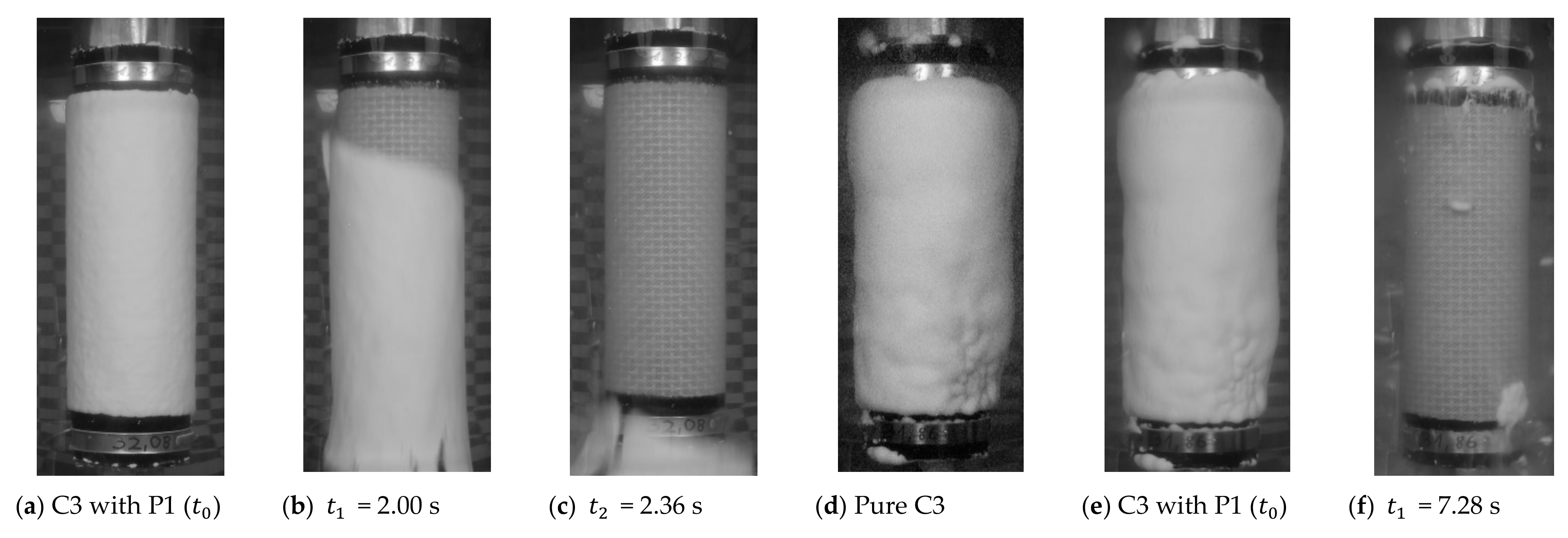
A striking feature of the cake formation is the formation of spherical cellulose heaps on the fabric. During filtration, these form “mountains and valleys”, which lead to an uneven cake diameter; see Figure 8. One reason for this is the low specific cake resistance. This means that the particles do not accumulate in the thinnest parts of the cake and compensate for differences in height. With small cake resistances, the total resistance of the cake and fabric increases only slightly with increasing cake height. However, the flow is reciprocal to the resistance. If the resistance is higher at any point, less fluid also flows through it and the cake formation rate decreases. Thus, a uniform cake is formed for particles with greater cake resistance [11].
C1 has a small cake resistance of 4.5 × 10¹¹ m−2 in this fabric, which increases the total resistance only insignificantly. In comparison, the cake resistance of P1 is 4.2 × 10¹³ m−2 and is larger than cellulose by a factor of 102. Accordingly, the cake resistance is the determining factor, which indicates the flow velocity through the filter. This results in very non-uniform cakes, since the flow resistance of the forming cake is relatively small and there is no flow-related equalization of the cake thickness. A disadvantage is the non-uniform distribution of the particles with respect to the subsequent filtration with cellulose as a precoat layer. It is to be expected that with low precoat thickness, part of the filter will not be occupied and thus will not be able to perform its purpose as a filter aid at this point; see Figure 8a). By the time the individual cellulose particles bind together to form a fully wetted surface, the cake has a height of between 0.6 and 0.8 mm. A multiple determination with a constant cellulose quantity of 1.43 g then gives a cake thickness of 0.7 mm, which is why this size is used for the following precoating.
In Figure 8, the difference between the two cakes with a surface occupancy of 0.53 kg∙m−2 lies in an increasing suspension concentration for e. Here, the influence of the suspension concentration can be seen, analogous to [20]. The cake heights used for the following precoat filtration are shown in Figure 9.

5.3.3. Cleaning Behavior with Additional Precoat Layer

Several differences can be identified between the backwashes of the pure particle systems and the backwashes with the precoat layer.
In filtration with an additional precoat layer, the basic shape of the filter cake depends on the precoat. The particle system, which usually has a much higher specific cake resistance, then lies evenly on the precoat layer. Unevenness in the precoat means an uneven filter cake, as can be seen from Figure 8d,e. Here, as a result of the high permeability, the precoat layer has accumulated in the lower half of the filter cartridge, creating a drop shape on which the filter cake subsequently builds up. This is counterproductive for a complete discharge, since there is always a predetermined breaking point at the thinnest part of the cake in the case of unevenness.
Another effect of precoating is that the overall diameter increases with an additional precoat layer. With constant concentration and filtrate quantity of the particle system, this consequently leads to a thinner filter cake, which has lower stability. An evaluation of LSM images of the filter cake on the pressurized filter cell has shown that particles not only settle on the surface of the cake, but also penetrate the cake and deposit there via depth filtration of the filter cake. Accordingly, an exact determination of the height of the individual layers is not possible in this combination of C1 and P1. This can also be explained by the PGV of C1 and P1. The x 90 , 3 value of P1 with 28.95 μm is below the x 10 , 3 value of C1 with 32.95 μm. This means that the largest particles in P1 are still several μm smaller than the smallest of cellulose C1. For the particles to be deposited on the surface, the quotient of the pore size of the cake particle size must not fall below 0.4 to achieve a sieving effect or to allow solid bridges [19]. The relationship between pore size and particle diameter is represented by the Young–Laplace equation for a heap [24]. From this equation, assuming a monomodal system, a pore size of 2/3 of the Sauter diameter can be determined. This explains the particle breakdown of P1 through the filter cake. The resulting cake diameters and backwash quantities are shown in Table 2 and Table 3.
This shows that when C1 is used, a larger backflush volume is required because of an increasing backwashing duration at a constant backwashing volume flow. For a total cake thickness of 1.4 mm, this amounts to 1.4 L∙m−2. Compared to the complete discharge of the pure particle system with a required backwashing volume of 0.23 L∙m−2, this is an additional volume requirement by a factor of six. Cellulose C1 is thus considered unsuitable not only for turbidity measurement but also with a focus on regeneration quality.
C2 has the largest particles when viewed from the PGV and therefore forms a cake with the largest pores. This is evident during filtration, as no particles from P1 and P2 are deposited on the cake surface. The particles deposit in the cake, with the main part collecting directly on the tissue surface. The fact that there is nevertheless no particle breakdown after turbidity measurement is attributed to the swelling behavior and compression close to the filter, named the skin effect. During the subsequent regeneration, only the precoat layer comes off and the particle layer remains adhered to the filter. Increasing the cake thickness to that of the manufacturer according to option 2 also does not improve the regeneration. Only the particle system P3 shows surface filtration with C2 as the precoat and is completely removed even after cleaning. However, clean regeneration is possible with P3 even without the Precoat, which makes the use of Precoat unnecessary. Therefore, the cellulose fibre C2 is classified as “unsuitable”.
Of all the cellulose fibres tested, C3 is the only one that can produce a complete discharge at 1.0 mm cake thickness. The filtration of the particle systems is now carried out for this cake height at different heights with subsequent backwashing. At all measured cake heights of the particle system, a complete discharge can be seen. Accordingly, the particles have no direct influence on the cleaning behavior. A similar behavior can be observed at the application rate recommended by the manufacturer. Here, too, the discharge of the filter cake behaves similarly to the discharge of the pure precoat layer. The manufacturer’s suggested quantity of 1 kg∙m−2 is therefore too high, and according to the tests, a quantity of 0.13 kg∙m−2 cellulose is sufficient for a cleansing with optically complete regeneration, independent of the particle quantity; see Figure 10a–c.
When using a used filter, an uneven filter cake is also present, similar to C1. If the filter is extremely dirty, there may be areas without continuous precoat wetting; see Figure 10d–f. On subsequent backwashing, this leaves residual contamination on the filter in zones without a precoat. Such contamination of the filter cannot be removed by backwashing and must be treated by other cleaning methods. These include cleaning by acids or ultrasonic methods [25]. The problem with these sites is that this area can no longer be used for filtration. The free filter area and thus the possible hydraulic load of the filter therefore decrease. Consequently, if a fabric is contaminated, an additional application of a precoat layer does not help to reduce the surface loading of the filter after regeneration.

6. Conclusions

The experiments carried out within the scope of this investigation include the influence of the filter aid as a precoat on:
  • the filter medium and filter cake resistance according to [7];
  • the gravimetrically determined turbidity impact;
  • the cake release at the backwash filter according to [8].
From the pressurized filter cell tests, it was observed that the difference in shape of the particles is decisive for the depth of penetration into the fabric. Needle and flaky shaped particles tend to deposit on the surface of the fabric, whereas particles with an orthorhombic structure can penetrate far into the fabric and increase the filter media resistance in continuous tests. No dependence on the precoat material can be seen in the filter cake resistance since this usually has a much lower resistance to the particle system. The filter cake resistance is therefore dominated by the resistance of the particle system but is constantly below that of pure particle systems due to slight mixing with the filter aid.
The advantage of precoating with a lower turbidity impact cannot be demonstrated with all cellulose fibres. While with C2 and C3, the turbidity impact is practically eliminated, with C1, five times the amount of particles penetrated through the fabric. Therefore, no general improvement of the turbidity impact can be assumed through the use of filter aids. In general, the filter aid resistance is a good method of determining the suitability of the filter aids since the turbidity impact behaves according to this.
On the backwashing filter, an improvement in regeneration performance can be noted with C3 as the filter aid. With C3, the complete discharge is independent of the number of particles filtered by the particle system. Thus, a particle layer of any thickness can be applied to the precoat layer in combination with the 11 µm satin fabric since the adhesion forces that cause the cake to adhere to the fabric depend only on the filter aid [23]. This in turn is offset by a larger required backwash volume, up to three times, because of the greater cake height. Increasing the amount of precoat does not improve the regeneration result. C1 shows a resuspension tendency during regeneration. The necessary cohesive force to hold the cake together comes only from the subsequent particle system. Thus, again, large layer thicknesses are needed to regenerate this in a complete discharge. Without a complete discharge, a large amount of fluid must subsequently be used to remove the remaining cake. Increasing the layer thickness enhances depth filtration but is not proportional to the improvement in regeneration.

Author Contributions

Conceptualization, V.B. and P.M.; Data curation, V.B.; Formal analysis, V.B. and P.M.; Funding acquisition, P.M. and H.N.; Investigation, V.B.; Methodology, V.B.; Project administration, P.M.; Resources, P.M.; Software, V.B.; Supervision, P.M., M.G. and H.N.; Validation, V.B.; Visualization, V.B.; Writing—original draft, V.B.; Writing—review & editing, P.M., M.G. and H.N. All authors have read and agreed to the published version of the manuscript.

Funding

This research received no external funding.

Institutional Review Board Statement

Not applicable.

Informed Consent Statement

Not applicable.

Data Availability Statement

Not applicable.

Acknowledgments

The authors would like to thank the German Federation of Industrial Research Associations (AiF) for the financial support (IGF number 18591 N). The authors would also like to thank all colleagues and students for the support in writing this paper. Furthermore, the authors would like to thank the company J. Rettenmaier & Söhne GmbH + Co KG, and especially Eberhard Gerdes and Sebastian Lösch, for providing and advising the selection of suitable precoat materials. We acknowledge support from the KIT-Publication Fund of the Karlsruhe Institute of Technology.

Conflicts of Interest

The authors declare no conflict of interest.

Abbreviations

SymbolDescriptionUnit
A Filter aream2
d h Hydraulic diameterm
F H Adhesive forceN
H F C Filter cake heightm
R F M Filter media resistancem−1
V F Filtrate volumem3
V ˙ F Filtrate volume flowm3∙s−1
x 50 , 3 Mass/volume modal valuem
α H Specific filter cake resistancem−2
Δ p Pressure differencePa
ε Porosity-
η f Viscosity of the fluidPa∙s

References

  1. Purchas, D.B.; Sutherland, K. Handbook of Filter Media, 2nd ed.; Elsevier: Amsterdam, The Netherlands, 2002. [Google Scholar]
  2. Ripperger, S.; Schnitzer, C. Die Barrierewirkung von Geweben Teil 1: Textiltechnische Charakterisierung und Barrieremechanismen. Filtr. Sep. 2005, 19, 110–117. [Google Scholar]
  3. Schnitzer, C.; Ripperger, S. Die Barrierewirkung von Geweben Teil 2: Experimentelle Methoden zur Bestimmung von Gewebeeigenschaften. Filtr. Sep. 2005, 19, 166–173. [Google Scholar]
  4. Ripperger, S. Die Barrierewirkung von Geweben Teil 3: Auswahl von Geweben zur Kuchenfiltration. Filtr. Sep. 2005, 19, 284–289. [Google Scholar]
  5. Ripperger, S. Die Barrierewirkung von Geweben Teil 6: Einfluss des Filtermittels auf die Kuchenfiltration. Filtr. Sep. 2008, 22, 6–9. [Google Scholar]
  6. Bächle, V.; Morsch, P.; Fränkle, B.; Gleiß, M.; Nirschl, H. Interaction of Particles and Filter Fabric in Ultrafine Filtration. Eng. Adv. Eng. 2021, 2, 9. [Google Scholar] [CrossRef]
  7. Verein Deutscher Ingenieure. VDI 2762: Filtrierbarkeit von Suspensionen Bestimmung des Filterkuchenwiderstands; Verein Deutscher Ingenieure e.V.: Düsseldorf, Germany, 2010. [Google Scholar]
  8. Morsch, P.; Anlauf, H.; Nirschl, H. The influence of filter cloth on cake discharge performances during backwashing into liquid phase. Sep. Purif. Technol. 2021, 254, 117549. [Google Scholar] [CrossRef]
  9. Fränkle, B.; Morsch, P.; Nirschl, H. Regeneration assessments of filter fabrics of filter presses in the mining sector. Miner. Eng. 2021, 168, 106922. [Google Scholar] [CrossRef]
  10. Christensen, M.L.; Klausen, M.M.; Christensen, P.V. Test of precoat filtration technology for treatment of swimming pool water. Water Sci. Technol. 2017, 77, 748–758. [Google Scholar] [CrossRef]
  11. Morsch, P.; Ginisty, P.; Anlauf, H.; Nirschl, H. Factors influencing backwashing operation in the liquid phase after cake filtration. Chem. Eng. Sci. 2020, 213. [Google Scholar] [CrossRef]
  12. Hackl, A.; Heidenreich, E.; Hoflinger, W.; Tittel, R. Filterhilfsmittelfiltration. Fortschr. VDI Reihe 3 1993, 348, 1–5. [Google Scholar]
  13. Heertjes, P.; Zuideveld, P. Clarification of liquids using filter aids Part III. Cake Resistance in surface filtration. Powder Technol. 1978, 19, 45–64. [Google Scholar] [CrossRef]
  14. Heertjes, P.M.; Zuideveld, P.L. Clarification of liquids using filter aids Part II. Depth filtration. Powder Technol. 1978, 19, 31–43. [Google Scholar] [CrossRef]
  15. Khirouni, N.; Charvet, A.; Drisket, C.; Ginestet, A.; Thomas, D.; Bémer, D. Precoating for improving the cleaning of filter media clogged with metallic nanoparticles. Process. Saf. Environ. Prot. 2021, 147, 311–319. [Google Scholar] [CrossRef]
  16. Zeller, A. Substitution der Kieselgur Durch Regenerierbare Zellulosefasern Auf Einem Neuartigen Filtrationssystem Für Brauereien. Ph.D. Thesis, Technische Universität Bergakademie Freiberg, Freiberg, Germany, 2011. [Google Scholar]
  17. Kain, J. Entwicklung und Verfahrenstechnik Eines Kerzenfiltersystems (Twin-Flow-System ) als Anschwemmfilter. Ph.D. Thesis, Technische Universität München, München, Germany, 2005. [Google Scholar]
  18. Kuhn, M.; Briesen, H. Dynamic Modeling of Filter-Aid Filtration Including Surface- and Depth-Filtration Effects. Chem. Eng. Technol. 2016, 39, 425–434. [Google Scholar] [CrossRef]
  19. Rushton, A. Effect of Filter Cloth Structure on Flow Resistance, Bleeding, Blinding and Plant performance. Chem. Eng. 1970, 273, 88–94. [Google Scholar]
  20. Anlauf, H. Filtermedien zur Kuchenfiltration-Schnittstelle Zwischen Suspension und Apparat. Chem. Ing. Tech. 2007, 79, 1821–1831. [Google Scholar] [CrossRef] [Green Version]
  21. Tiller, F.M.; Green, T.C. Role of porosity in filtration IX skin effect with highly compressible materials. AIChE J. 1973, 19, 1266–1269. [Google Scholar] [CrossRef]
  22. Ripperger, S. Optimierung von Rückspülfiltern für Flüssigkeiten. Filtr. Sep. 2008, 22, 68–72. [Google Scholar]
  23. Morris, K.; Allen, R.W.; Clift, R. Adhesion of Cakes to Filter Media. Filtr. Sep. 1987, 24, 41–45. [Google Scholar]
  24. Lengweiler, P. Modelling Deposition and Resuspension of Particles on and from Surfaces. Ph.D. Thesis, Swiss Federal Institute of Technology Zürich, Zürich, Switzerland, 2000. [Google Scholar]
  25. Gruschwitz, F.; Nirschl, H.; Anlauf, H. Optimized backflushing process for fibrous media in engine oil filtration and enhancement by ultrasound. Chem. Eng. Technol. 2013, 36, 467–473. [Google Scholar] [CrossRef]
Figure 1. Continuous addition of the filter aid with the suspension (a) and addition as a primary filter cake (b).
Eng 02 00012 g001
Figure 2. Schematic representation of the test plant during filtration of the precoat layer (I), displacement of the suspension with clear water (II), and subsequent running through of the same sequence with filtration of the suspension (I) and renewed displacement by clear water. This is followed by regeneration (III) through discharge of the filter cake and cake removal out of the process room (IV).
Eng 02 00012 g002
Figure 3. Microscopic image of the investigated filter aids (Cellulose) of J. Rettenmaier & Söhne GmbH + Co KG with fibrous (C1,C2) and orthorhombic (C3) structures, as well as the filter cake resistance and particle size distribution.
Eng 02 00012 g003
Figure 4. Filter media resistances of the pure filter aids, particle systems, and their combinations.
Eng 02 00012 g004
Figure 5. Filter cake resistances of the pure filter aids, particle systems, and their combinations.
Eng 02 00012 g005
Figure 6. Mass of residual particles of the 200 mL filtrate on the pressurized filter cell using all particles and cellulose used as a pure substance and precoat.
Eng 02 00012 g006
Figure 7. Backwashing behavior of the pure C1 layer with a surface loading of 0.13 kg∙m−2 and the resulting cake height of 0.7 mm.
Eng 02 00012 g007
Figure 8. Resultant cake thickness at time t0 with ascending area occupancy.
Eng 02 00012 g008
Figure 9. Cake height of the precoat layer.
Eng 02 00012 g009
Figure 10. Regeneration of C1 and P1 with 0 13 kg∙m−2 each for a new filter (ac) and a regeneration of C1 (1.07 kg∙m−2) with P1 (2.13 kg∙m−2) for a dirty filter (df).
Eng 02 00012 g010
Table 1. Regeneration behavior in a satin fabric with a mesh size of 11 µm and particle systems based on [8,11].
ParticleConcentration/kg∙L−1Particle Volume/kg∙m−2Cake Height/mmBackwashing Volume/L∙m−2Remark
P15.711.070.7 ± 0.112.2 ± 0.50Complete Discharge
P25.711.070.6 ± 0.070.3 ± 0.01
P31.430.130.2 ± 0.070.3 ± 0.03
Table 2. Cake height and backwashing volume at a cellulose quantity of 0.13 kg∙m−2 (option 1) with the respective particle systems at a backwashing pressure of 0.5 bar.
ParticleConcentration/kg∙L−1Particle Volume/kg∙m−2Cake Height/mmBackwashing Volume/L∙m−2Remark
C1–P122.862.131.4 ± 0.41.40 ± 0.22Incomplete discharge
C1–P21.430.131.1 ± 0.21.19 ± 0.10Resuspended discharge
C1–P31.430.131.2 ± 0.20.53 ± 0.06Complete discharge
C2–P11.430.132.0 ± 0.3> 5No filtration effect
C2–P21.430.131.5 ± 0.3> 5No filtration effect
C2–P31.430.131.4 ± 0.41.55 ± 0.18Incomplete good discharge
C3–P11.430.130.9 ± 0.30.76 ± 0.08Complete discharge
C3–P21.430.130.9 ± 0.10.23 ± 0.02Complete discharge
C3–P31.430.130.9 ± 0.20.24 ± 0.04Complete discharge
Table 3. Cake height and backwashing volume at a cellulose quantity of 1 kg∙m−2 (option 2) with particle system P1 at a backwashing pressure of 0.5 bar.
ParticleConcentration/kg∙L−1Particle Volume/kg∙m−2Cake Height/mmBackwashing Volume/L∙m−2Remark
C1–P122.862.133.1 ± 0.21.07 ± 0.10Resuspended discharge
C2–P15.711.075.3 ± 0.7>5No filtration effect
C3–P11.430.132.9 ± 0.32.19 ± 0.14Complete discharge
Publisher’s Note: MDPI stays neutral with regard to jurisdictional claims in published maps and institutional affiliations.