

Analysis and Design Methodology of Radial Flux Surface-Mounted Permanent Magnet Synchronous Motors

 ,
,  ,
,  and
and 
Abstract
:1. Introduction
2. Materials and Methods
2.1. Design Equations and Methodology
2.2. Design of Dual-Rotor and Single-Rotor Motors
3. Results
3.1. Dual-Rotor Motor Results
3.2. Single-Rotor Motor Results
4. Discussion
Author Contributions
Funding
Data Availability Statement
Conflicts of Interest
References
- Sanguesa, J.A.; Torres-Sanz, V.; Garrido, P.; Martinez, F.J.; Marquez-Barja, J.M. A Review on Electric Vehicles: Technologies and Challenges. Smart Cities 2021, 4, 372–404. [Google Scholar] [CrossRef]
- de Almeida, A.T.; Fong, J.; Falkner, H.; Bertoldi, P. Policy options to promote energy efficient electric motors and drives in the EU. Renew. Sustain. Energy Rev. 2017, 74, 1275–1286. [Google Scholar] [CrossRef]
- Bouloukza, I.; Mordjaoui, M.; Kurt, E.; Bal, G.; Ökmen, C. Electromagnetic design of a new radial flux permanent magnet motor. J. Energy Syst. 2018, 2, 13–27. [Google Scholar] [CrossRef]
- Jung, Y.-H.; Park, M.-R.; Lim, M.-S. Asymmetric Rotor Design of IPMSM for Vibration Reduction Under Certain Load Condition. IEEE Trans. Energy Convers. 2020, 35, 928–937. [Google Scholar] [CrossRef]
- Karnavas, Y.L.; Chasiotis, I.D.; Korkas, C.D.; Amoutzidis, S.K. Modelling and multiobjective optimization analysis of a permanent magnet synchronous motor design. Int. J. Numer. Model. Electron. Netw. Devices Fields 2017, 30, e2232. [Google Scholar] [CrossRef]
- Kim, J.-H.; Seo, J.-M.; Jung, H.-K.; Won, C.-Y. Analysis and Design of a Novel-Shape Permanent Magnet Synchronous Motor for Minimization of Torque Ripple and Iron Loss. J. Magn. 2014, 19, 411–417. [Google Scholar] [CrossRef]
- Koo, B.; Kim, J.; Nam, K. Halbach Array PM Machine Design for High Speed Dynamo Motor. IEEE Trans. Magn. 2021, 57, 1–5. [Google Scholar] [CrossRef]
- Kwon, J.-W.; Li, M.; Kwon, B.-I. Design of V-Type Consequent-Pole IPM Machine for PM Cost Reduction With Analytical Method. IEEE Access 2021, 9, 77386–77397. [Google Scholar] [CrossRef]
- Park, J.; Paul, S.; Chang, J.; Hwang, T.; Jongsu, Y. Design and comparative survey of high torque coaxial permanent magnet coupling for tidal current generator. Int. J. Electr. Power Energy Syst. 2020, 120, 105966. [Google Scholar] [CrossRef]
- Scuiller, F.; Becker, F.; Zahr, H.; Semail, E. Design of a Bi-Harmonic 7-Phase PM Machine with Tooth-Concentrated Winding. IEEE Trans. Energy Convers. 2020, 35, 1567–1576. [Google Scholar] [CrossRef]
- Shi, Z.; Sun, X.; Cai, Y.; Xiang, T.; Chen, L. Design optimisation of an outer-rotor permanent magnet synchronous hub motor for a low-speed campus patrol EV. IET Electr. Power Appl. 2020, 14, 2111–2118. [Google Scholar] [CrossRef]
- Wu, S.; Zhao, X.; Jiao, Z.; Luk, P.C.; Jiu, C. Multi-Objective Optimal Design of a Toroidally Wound Radial-Flux Halbach Permanent Magnet Array Limited Angle Torque Motor. IEEE Trans. Ind. Electron. 2017, 64, 2962–2971. [Google Scholar] [CrossRef]
- Yang, Y.; Castano, S.M.; Yang, R.; Kasprzak, M.; Bilgin, B.; Sathyan, A.; Dadkhah, H.; Emadi, A. Design and Comparison of Interior Permanent Magnet Motor Topologies for Traction Applications. IEEE Trans. Transp. Electrif. 2017, 3, 86–97. [Google Scholar] [CrossRef]
- Yazdan, T.; Humza, M.; Ali, Q.; Hussain, A.; Kwon, B.-i. Design and analysis of a two-phase brushless DC motor with hybrid permanent magnet material for only-pull drive technique. Electr. Eng. 2021, 103, 2335–2343. [Google Scholar] [CrossRef]
- Kim, S.-m.; Jung, W.-S.; Kim, W.-H.; Bang, T.-K.; Lee, D.-H.; Kim, Y.-J.; Choi, J.-Y. Optimal Design of Permanent Magnet Synchronous Machine Based on Random Walk Method and Semi 3D Magnetic Equivalent Circuit Considering Overhang Effect. Energies 2022, 15, 7852. [Google Scholar] [CrossRef]
- Li, X.; Sun, Z.; Sun, W.; Guo, L.; Wang, H. Design of Permanent Magnet-Assisted Synchronous Reluctance Motor with Low Torque Ripple. World Electr. Veh. J. 2023, 14, 82. [Google Scholar] [CrossRef]
- Qu, C.; Guo, Z.; Hu, Y.; Wang, X.; Han, F. Multi-Objective Optimization Design of a New Permanent Magnet Synchronous Motor Based on the Taguchi Method. Energies 2022, 15, 7347. [Google Scholar] [CrossRef]
- Wang, Z.; Tian, W.; Zhao, W. Magnet Slotting Design to Reduce High Order Electromagnetic Force and Vibration of Permanent Magnet Motor. Energies 2022, 15, 8684. [Google Scholar] [CrossRef]
- Xu, J.; Zhang, L.; Meng, D.; Su, H. Simulation, Verification and Optimization Design of Electromagnetic Vibration and Noise of Permanent Magnet Synchronous Motor for Vehicle. Energies 2022, 15, 5808. [Google Scholar] [CrossRef]
- Gieras, J.F. Permanent Magnet Motor Technology: Design and Applications; CRC Press: Boca Raton, FL, USA, 2009. [Google Scholar]
- Hanselman, D.C. Brushless Permanent Magnet Motor Design; The Writers’ Collective: Cranston, RI, USA, 2003. [Google Scholar]
- Ronghai, Q.; Lipo, T.A. Analysis and modeling of air-gap and zigzag leakage fluxes in a surface-mounted permanent-magnet Machine. IEEE Trans. Ind. Appl. 2004, 40, 121–127. [Google Scholar] [CrossRef]
- Ronghai, Q.; Lipo, T.A. Design and parameter effect analysis of dual-rotor, radial-flux, toroidally wound, permanent-magnet machines. IEEE Trans. Ind. Appl. 2004, 40, 771–779. [Google Scholar] [CrossRef]
- Bhat, S.B.; Nikam, S.P.; Fernandes, B.G. Design and analysis of ferrite based permanent magnet motor for electric assist bicycle. In Proceedings of the 2014 International Conference on Electrical Machines (ICEM), Berlin, Germany, 2–5 September 2014; pp. 106–111. [Google Scholar]
- Lim, D.; Cho, Y.; Ro, J.; Jung, S.; Jung, H. Optimal Design of an Axial Flux Permanent Magnet Synchronous Motor for the Electric Bicycle. IEEE Trans. Magn. 2016, 52, 1–4. [Google Scholar] [CrossRef]
- Song, B.; Chang, K.; Choi, J. Design of an outer-rotor-type permanent magnet motor for electric scooter propulsion systems. In Proceedings of the 2010 International Power Electronics Conference—ECCE ASIA, Sapporo, Japan, 21–24 June 2010; pp. 2742–2763. [Google Scholar]
- Rasmussen, C.B.; Ritchie, E. Variable speed brushless DC motor drive for household refrigerator compressor. In Proceedings of the 1997 Eighth International Conference on Electrical Machines and Drives (Conf. Publ. No. 444), Cambridge, UK, 1–3 September 1997; pp. 128–132. [Google Scholar]
- Sun, L.; Cheng, M.; Jia, H. Analysis of a Novel Magnetic-Geared Dual-Rotor Motor With Complementary Structure. IEEE Trans. Ind. Electron. 2015, 62, 6737–6747. [Google Scholar] [CrossRef]
- Sun, L.; Cheng, M.; Tong, M. Key Issues in Design and Manufacture of Magnetic-Geared Dual-Rotor Motor for Hybrid Vehicles. IEEE Trans. Energy Convers. 2017, 32, 1492–1501. [Google Scholar] [CrossRef]


| Parameter | Description |
|---|---|
| Motor output power, W | |
| Efficiency without mechanical losses, % | |
| Nominal speed, rpm | |
| Peak back-EMF, V | |
| Number of phases | |
| Number of magnet poles | |
| Number of slots per phase | |
| Air gap length, m | |
| Radius to the upper side of the magnet, m | |
| Stator back-iron inner radius, m | |
| Motor axial length, m | |
| Steel core loss density vs. flux density and frequency | |
| Lamination stacking factor and steel mass density, kg/m3 | |
| Copper resistivity | |
| Bare copper filling factor | |
| Angular width of each magnet (radians) or magnet fraction | |
| Magnet residual flux density, T | |
| Rotor core flux density, T | |
| Air gap flux density, T | |
| Stator core flux density, T | |
| Stator tooth flux density, T | |
| Magnet recoil permeability | |
| Slot opening, m | |
| Shoe depth fraction |
| No. | Equation | Description |
|---|---|---|
| (1) | Mechanical speed, rad/s | |
| (2) | Electrical speed, rad/s | |
| (3) | Fundamental electrical frequency, Hz | |
| (4) | Torque from power | |
| (5) | Number of slots | |
| (6) | Number of slots per pole per phase | |
| (7) | Number of slots per pole | |
| (8) | Coil-pole fraction | |
| (9) | Angular pole pitch | |
| (10) | Angular slot pitch | |
| (11) | Slot pitch, electrical radians | |
| (12) | Inside stator radius | |
| (13) | Outside stator radius | |
| (14) | Pole pitch, inner part of the motor | |
| (15) | Pole pitch, outer part of the motor | |
| (16) | Coil pitch | |
| (17) | Slot pitch at air gap, inner part of the motor | |
| (18) | Slot pitch at air gap, outer part of the motor | |
| (19) | Tooth width at air gap | |
| (20) | Distribution factor | |
| (21) | Pitch factor | |
| (22) | Skew factor | |
| (23) | Magnet circumferential length | |
| (24) | Circumferential length between magnets | |
| (25) | Effective air gap for Carter coefficient | |
| (26) | Carter coefficient | |
| (27) | Effective air gap taking into account the slotting | |
| (28) | ||
| (29) | ||
| (30) | Air gap flux density | |
| (31) | Magnet working point | |
| (32) | Rotor back-iron width | |
| (33) | Outer radius of the inner rotor | |
| (34) | Inner radius of the inner rotor | |
| (35) | Inner radius of the outer rotor | |
| (36) | Outer radius of the outer rotor | |
| (37) | Air gap leakage flux coefficient | |
| (38) | Stator tooth width | |
| (39) | Total slot depth, inner part of the motor | |
| (40) | Conductor slot depth, inner part of the motor | |
| (41) | Slot area available for conductors | |
| (42) | Stator back-iron outer radius | |
| (43) | Total slot depth, outer part of the motor | |
| (44) | Terms needed for the calculation of | |
| (45) | Stator tooth width, outer part of the motor | |
| (46) | Stator back-iron width | |
| (47) | Number of turns per slot | |
| (48) | Bare area of one winding conductor | |
| (49) | Peak back-EMF | |
| (50) | Peak slot current | |
| (51) | Phase current | |
| (52) | Peak conductor current density | |
| (53) | Slot resistance | |
| (54) | End turn resistance | |
| (55) | Phase resistance | |
| (56) | Stator steel volume | |
| (57) | Ohmic power loss | |
| (58) | Core loss | |
| (59) | Efficiency without mechanical losses |
| Parameter | Value |
|---|---|
| 500 W | |
| ≥90% | |
| 1800 rpm | |
| 24 V | |
| 3 | |
| 8 | |
| 8 | |
| 0.6 mm | |
| 2.2 mm | |
| 70 mm | |
| 103 mm | |
| 82 mm | |
| 20 mm | |
| 0.9 | |
| 1.7 W/kg | |
| 7650 kg/m3 | |
| 17.2 nΩ/m | |
| 0.5 | |
| 0.84 | |
| 0.85 | |
| 0.4 T | |
| 0.5 T | |
| 0.514 T | |
| 0.272 T | |
| 1.6 T | |
| 1.5 T | |
| 1.5 T | |
| 1.05 | |
| 1 mm | |
| 2 mm | |
| 0.38 |
| Parameter | Value |
|---|---|
| 20 W | |
| ≥90% | |
| 1800 rpm | |
| 30 V | |
| 3 | |
| 4 | |
| 4 | |
| 0.35 mm | |
| 22 mm | |
| 37 mm | |
| 21 mm | |
| 0.9 | |
| 1.7 W/kg | |
| 7650 kg/m3 | |
| 17.2 nΩ/m | |
| 0.5 | |
| 0.84 | |
| 0.4 T | |
| 0.5 T | |
| 0.25 T | |
| 0.8 T | |
| 0.8 T | |
| 1.05 | |
| 1 mm | |
| 0.38 |
| Variable | Result |
|---|---|
| 120 Hz | |
| 2.652 Nm | |
| 24 | |
| 70.6 mm | |
| 100.8 mm | |
| 46.181 mm | |
| 68.762 mm | |
| 2.7 mm | |
| 2.7 mm | |
| 0.184 T | |
| 15.925 mm | |
| 15.956 mm | |
| 66.176 mm | |
| 122.056 mm | |
| 50.251 mm | |
| 106.1 mm | |
| 3.519 mm | |
| 3.243 mm | |
| 9.898 mm | |
| 167.353 × 10⁻⁶ m2 | |
| 21 | |
| 9.773 A | |
| 0.051 Ω | |
| 7.387 W | |
| 7.73 W | |
| 97.065% |
| Variable | Expected Value | Obtained Value | Error |
|---|---|---|---|
| Torque | 2.652 Nm | 2.4964 Nm | 5.87% |
| Total air gap flux density (inner and outer part of the motor) | 0.456 T | 0.437 T | 4.12% |
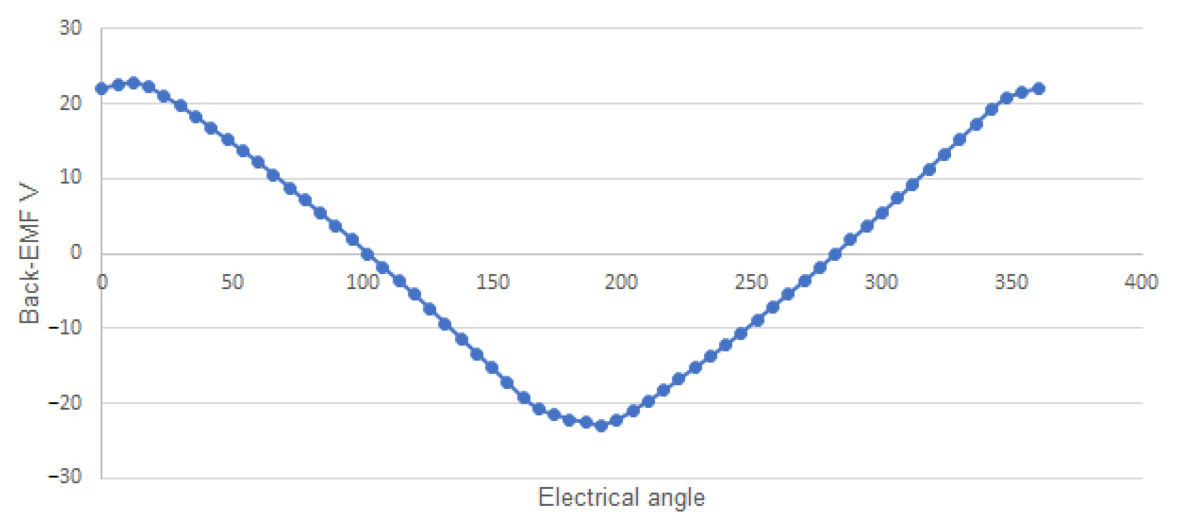
| Back-EMF | 24 V | 22.87 V | 4.71% |
| Efficiency | ≥90% | 97.065% | 7.065% |
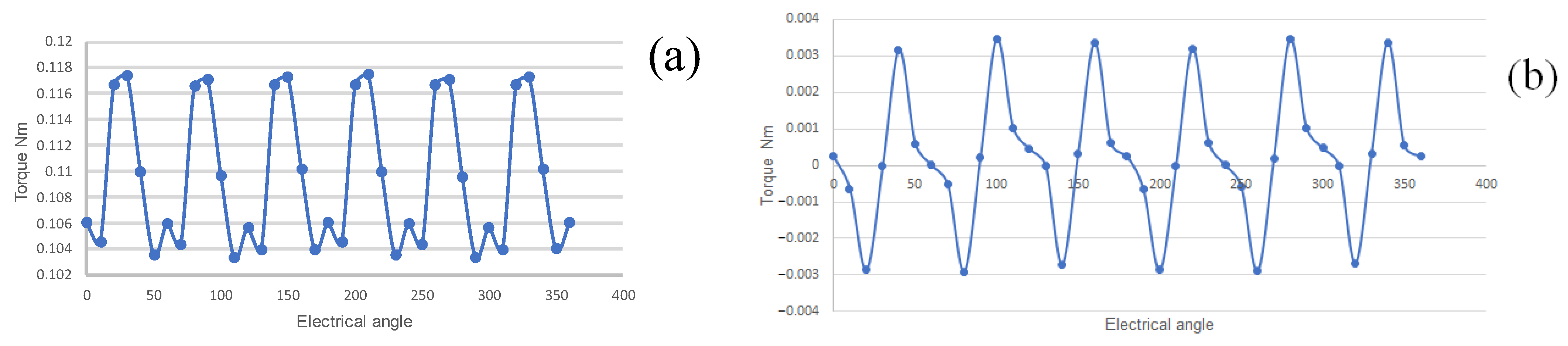
| Torque ripple | ≤20% | 14.37% | 5.63% |
| Variable | Result |
|---|---|
| 60 Hz | |
| 106.103 mNm | |
| 12 | |
| 22.35 mm | |
| 29.028 mm | |
| 1.08 mm | |
| 8.71 mm | |
| 20.92 mm | |
| 12.21 mm | |
| 3.835 mm | |
| 5.735 mm | |
| 159.418 × 10⁻⁶ m2 | |
| 344 | |
| 0.315 A | |
| 7.778 Ω | |
| 1.156 W | |
| 0.555 W | |
| 92.119% |
| Variable | Expected Value | Obtained Value | Error |
|---|---|---|---|
| Torque | 106.103 mNm | 109.273 mNm | 3% |
| Air gap flux density | 0.25 T | 0.246 T | 1.6% |
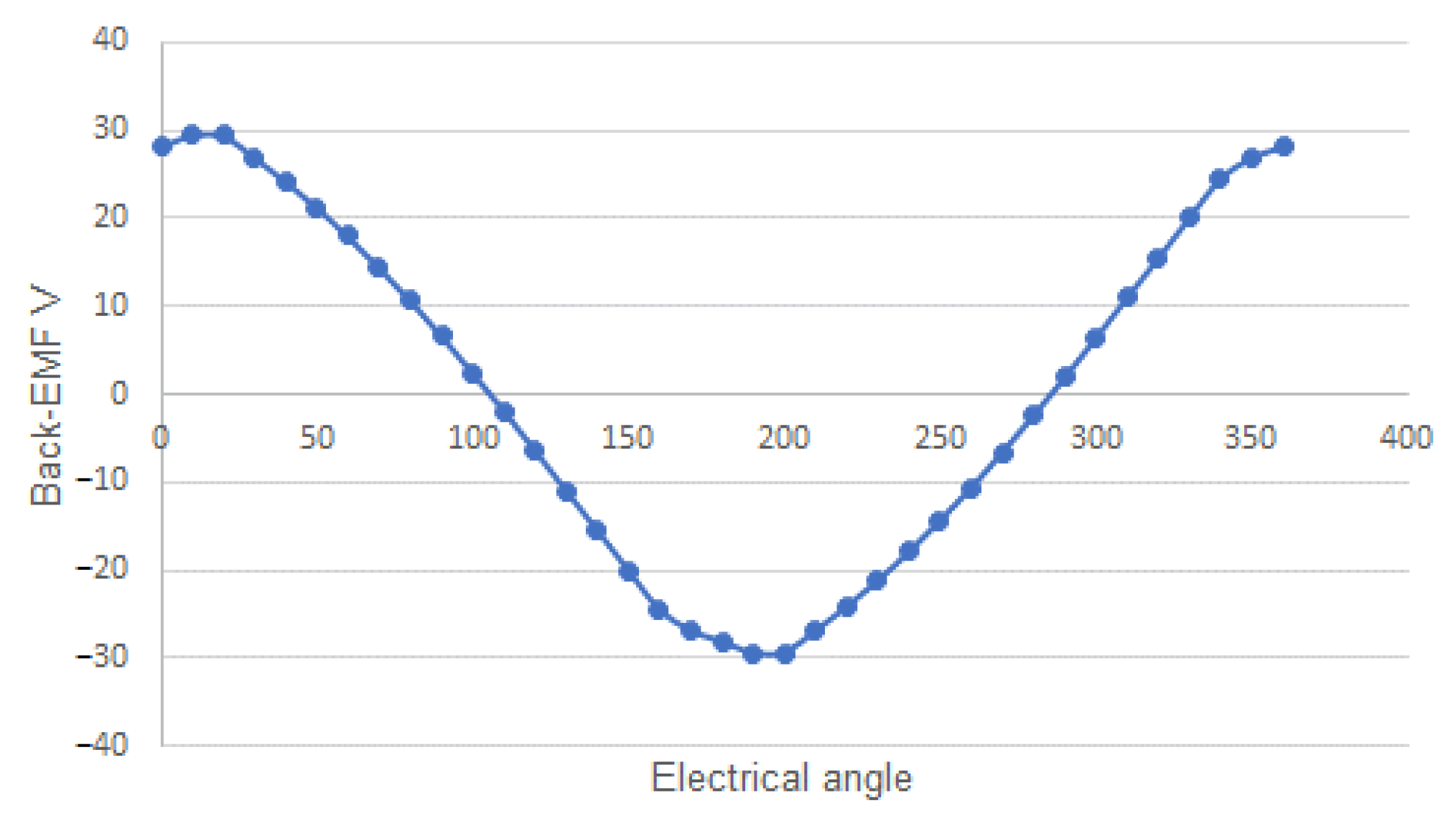
| Back-EMF | 30 V | 29.53 V | 1.57% |
| Efficiency | ≥90% | 92.408% | 2.408% |
| Torque ripple | ≤10% | 7.26% | 2.74% |
Disclaimer/Publisher’s Note: The statements, opinions and data contained in all publications are solely those of the individual author(s) and contributor(s) and not of MDPI and/or the editor(s). MDPI and/or the editor(s) disclaim responsibility for any injury to people or property resulting from any ideas, methods, instructions or products referred to in the content. |
© 2023 by the authors. Licensee MDPI, Basel, Switzerland. This article is an open access article distributed under the terms and conditions of the Creative Commons Attribution (CC BY) license (https://creativecommons.org/licenses/by/4.0/).
Share and Cite
Suriano-Sánchez, S.I.; Ponce-Silva, M.; Olivares-Peregrino, V.H.; De León-Aldaco, S.E.; Claudio-Sánchez, A.; Cortés-García, C. Analysis and Design Methodology of Radial Flux Surface-Mounted Permanent Magnet Synchronous Motors. Eng 2023, 4, 2840-2855. https://doi.org/10.3390/eng4040160
Suriano-Sánchez SI, Ponce-Silva M, Olivares-Peregrino VH, De León-Aldaco SE, Claudio-Sánchez A, Cortés-García C. Analysis and Design Methodology of Radial Flux Surface-Mounted Permanent Magnet Synchronous Motors. Eng. 2023; 4(4):2840-2855. https://doi.org/10.3390/eng4040160
Chicago/Turabian StyleSuriano-Sánchez, Sergio I., Mario Ponce-Silva, Víctor H. Olivares-Peregrino, Susana E. De León-Aldaco, Abraham Claudio-Sánchez, and Claudia Cortés-García. 2023. "Analysis and Design Methodology of Radial Flux Surface-Mounted Permanent Magnet Synchronous Motors" Eng 4, no. 4: 2840-2855. https://doi.org/10.3390/eng4040160