
Enhancing Wear Resistance of Drilling Motor Components: A Tribological and Materials Application Study
 , , , ,
Abstract
:1. Introduction
2. Literature Review
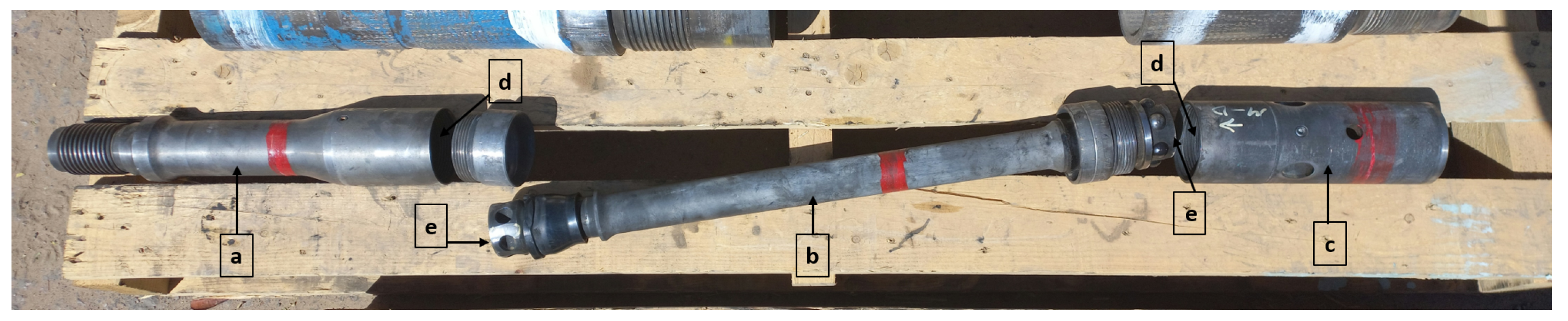
3. Experimental Work
3.1. Chemical Analysis
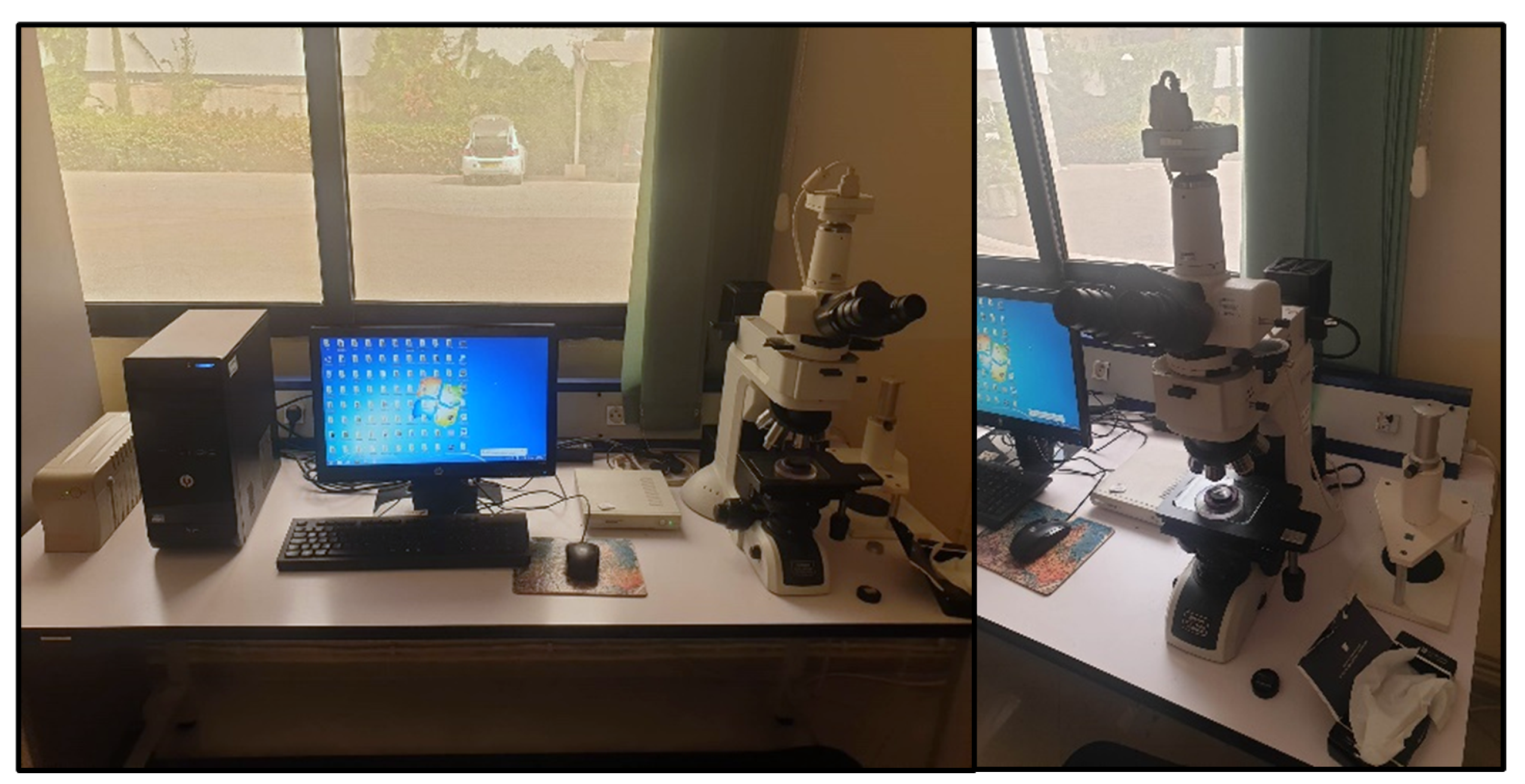
3.2. Microstructural Analysis
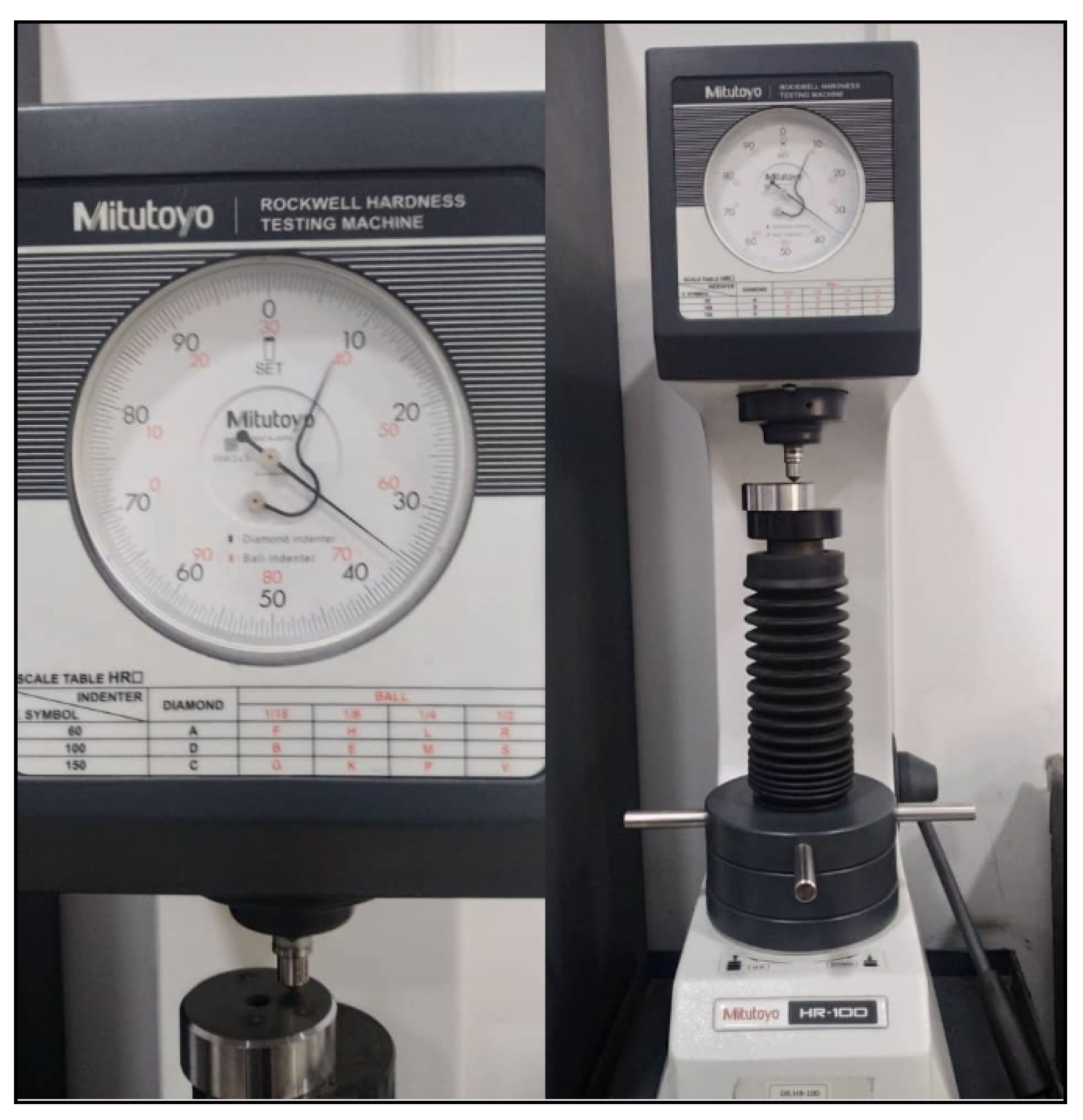
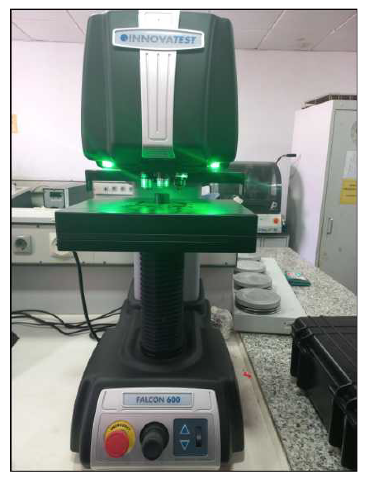
3.3. Hardness Testing
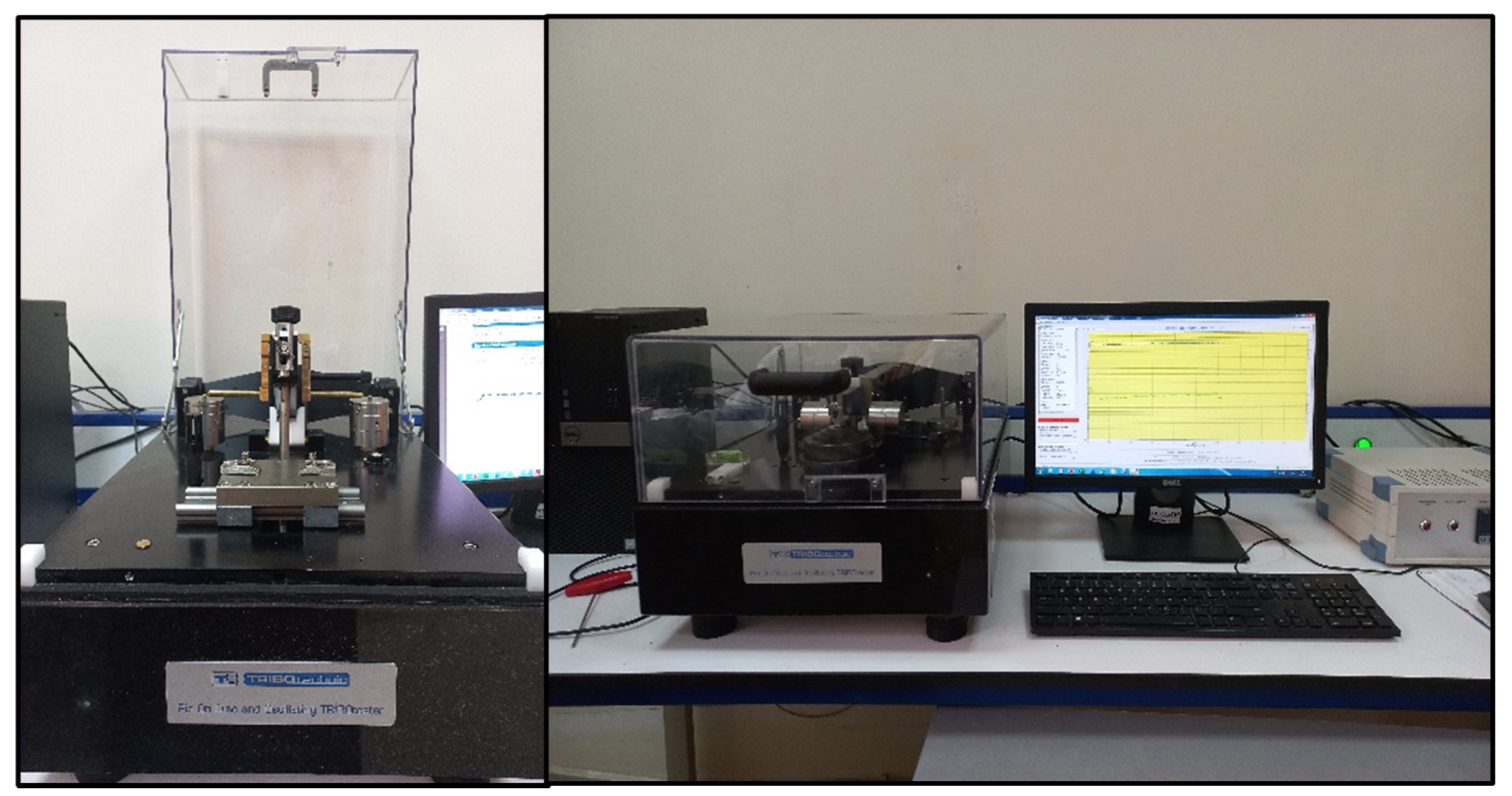
3.4. Tribometer
- •
- Speed: 110 mm/s.
- •
- Duration per load: 30 min.
- •
- Wear groove: 3 mm.
- •
- Load variations: 4 N, 6 N, 8 N, 10 N, and 12 N.
- •
- Sliding length: 200 m.
- •
- Environmental temperature: 23 °C.
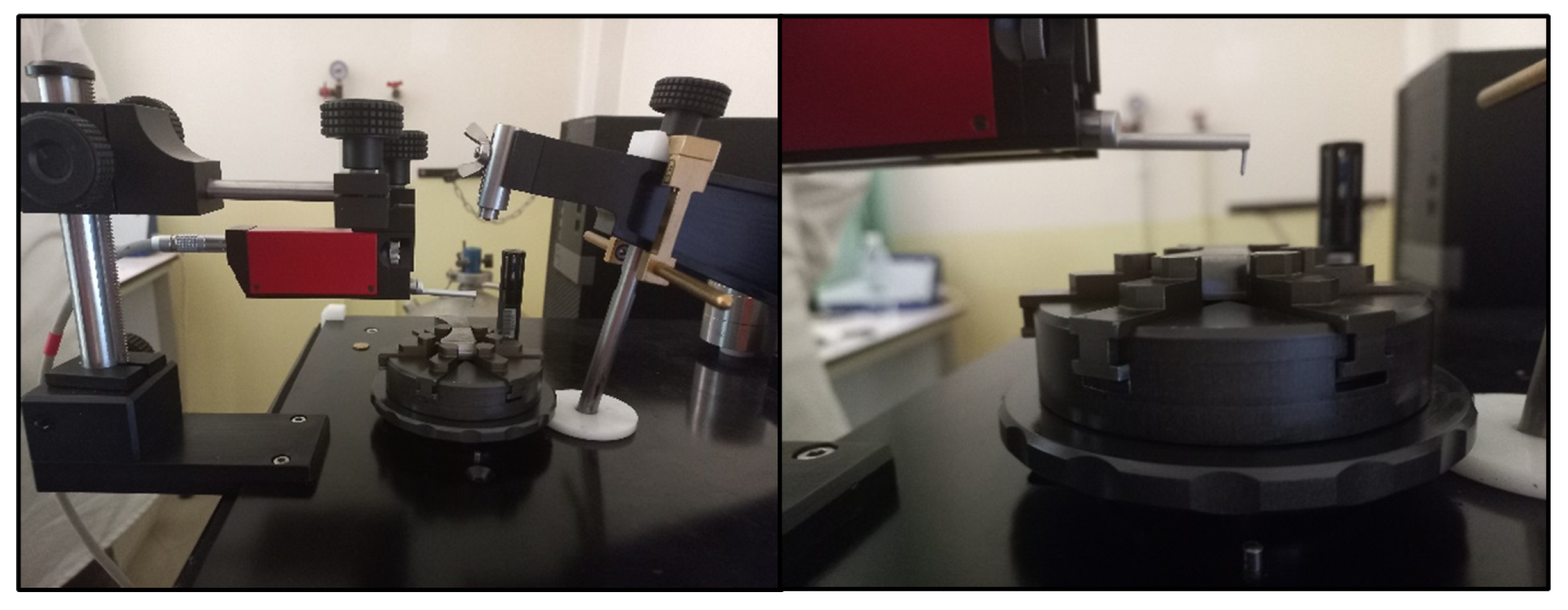
3.5. Profilometer
- •
- : wear coefficient (mm3/N.m).
- •
- S: track section (mm2).
- •
- n: number of rounds.
- •
- R: radius track (mm).
- •
- : normal load on friction surface (N).
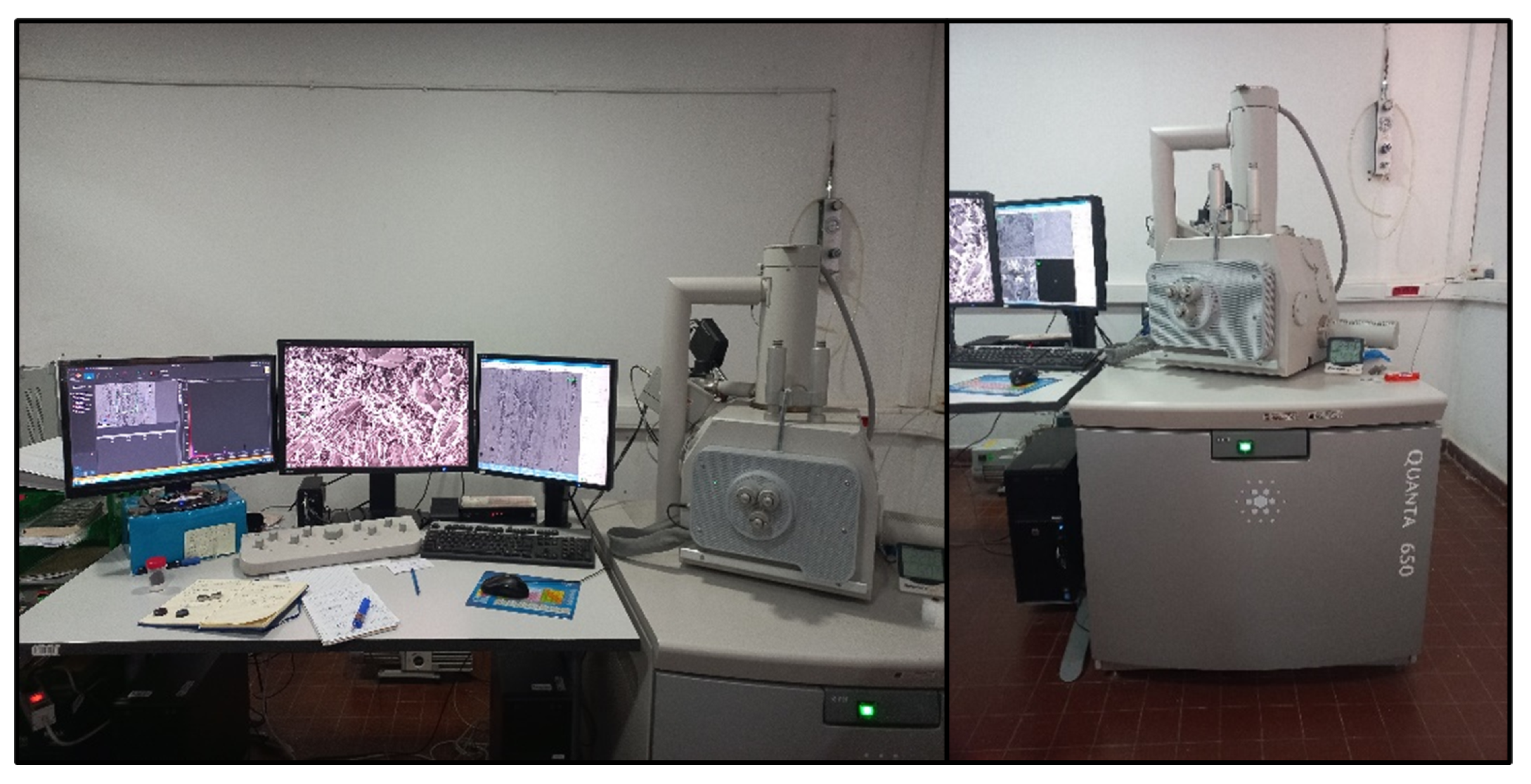
3.6. Scanning Electron Microscopy SEM
- •
- Surface examination: the steel samples’ surfaces are meticulously inspected for any imperfections, fractures, or applied surface treatments. Energy Dispersive X-ray Spectroscopy (EDS) is utilized to determine their elemental composition.
- •
- Wear mechanism identification: by offering magnified views of wear patterns, scratches, cracks, and other surface damages from the tribology test, SEM aids in pinpointing wear mechanisms, including adhesive, abrasive, or fatigue wear. This is vital for understanding wear causes and devising apt solutions.
4. Results and Discussion
4.1. Surface Treatment Characterization
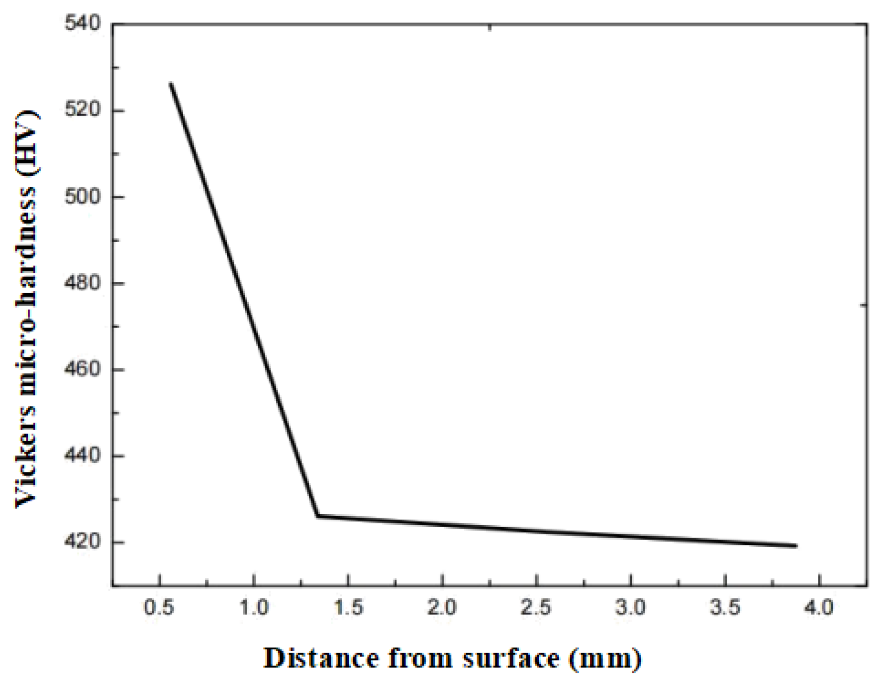
4.1.1. Microhardness Measurements
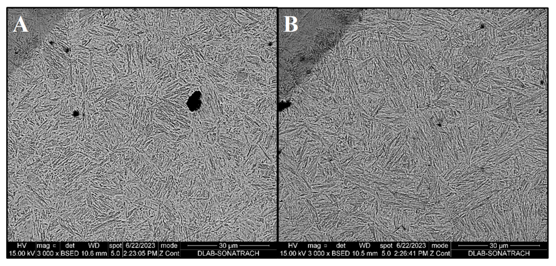
4.1.2. SEM Surface Treatment Characterization
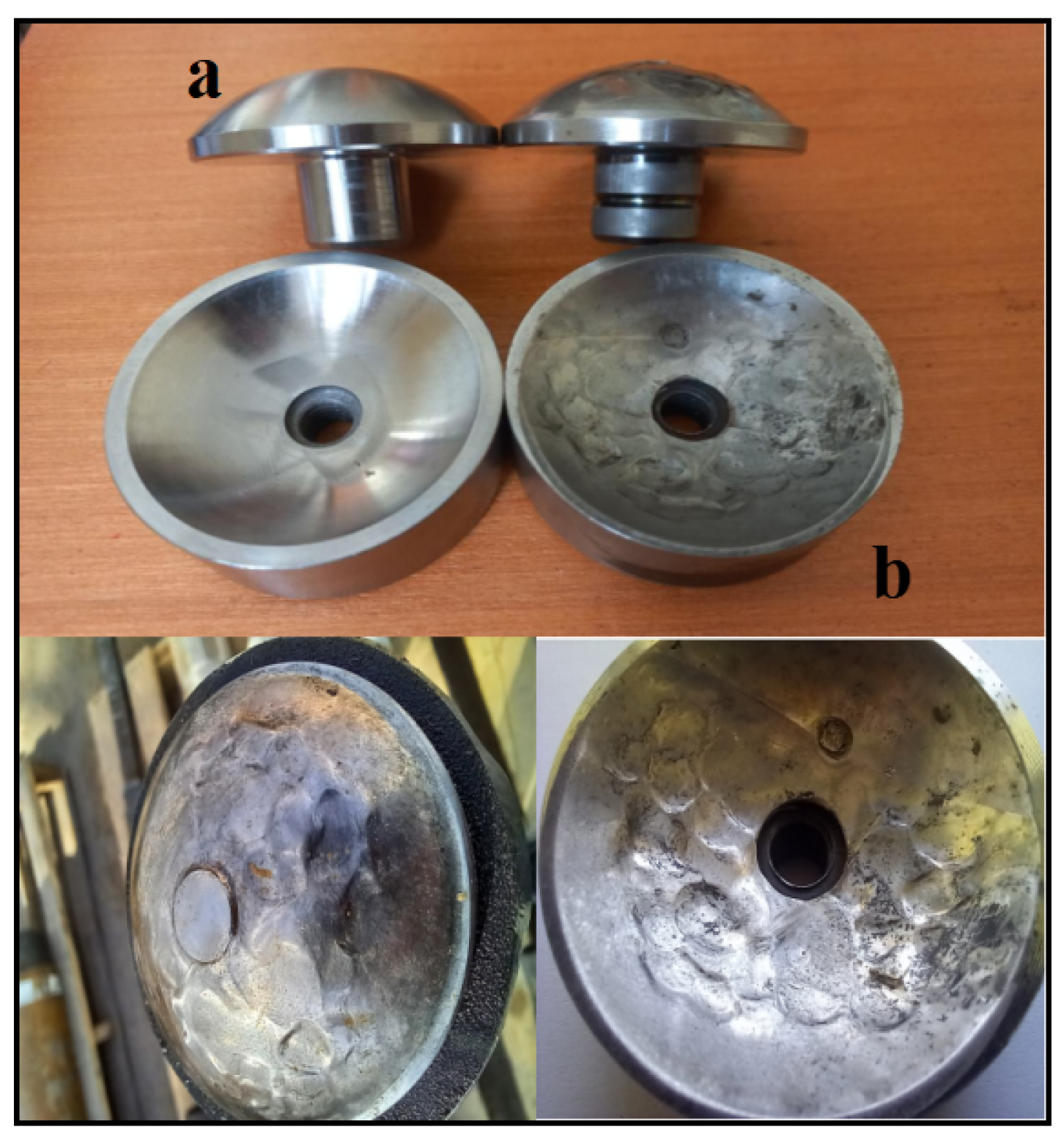
4.2. The Thrust Insert: AISI 9310
4.2.1. Chemical Composition
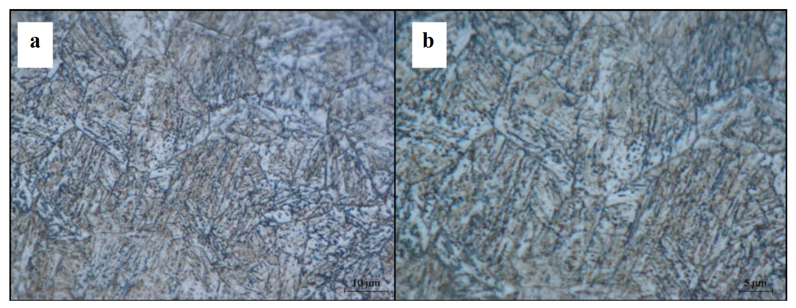
4.2.2. Optical Microstructure
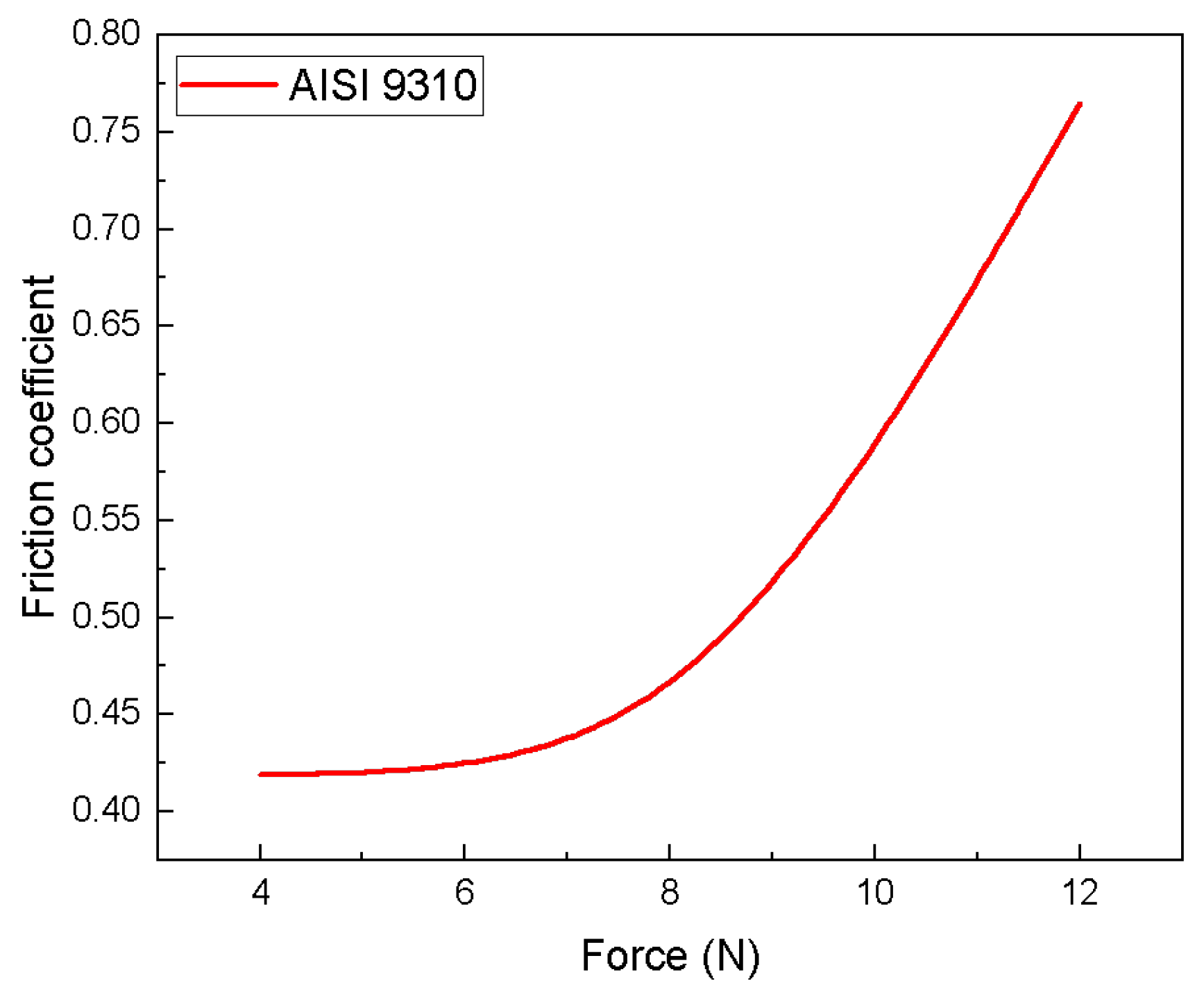
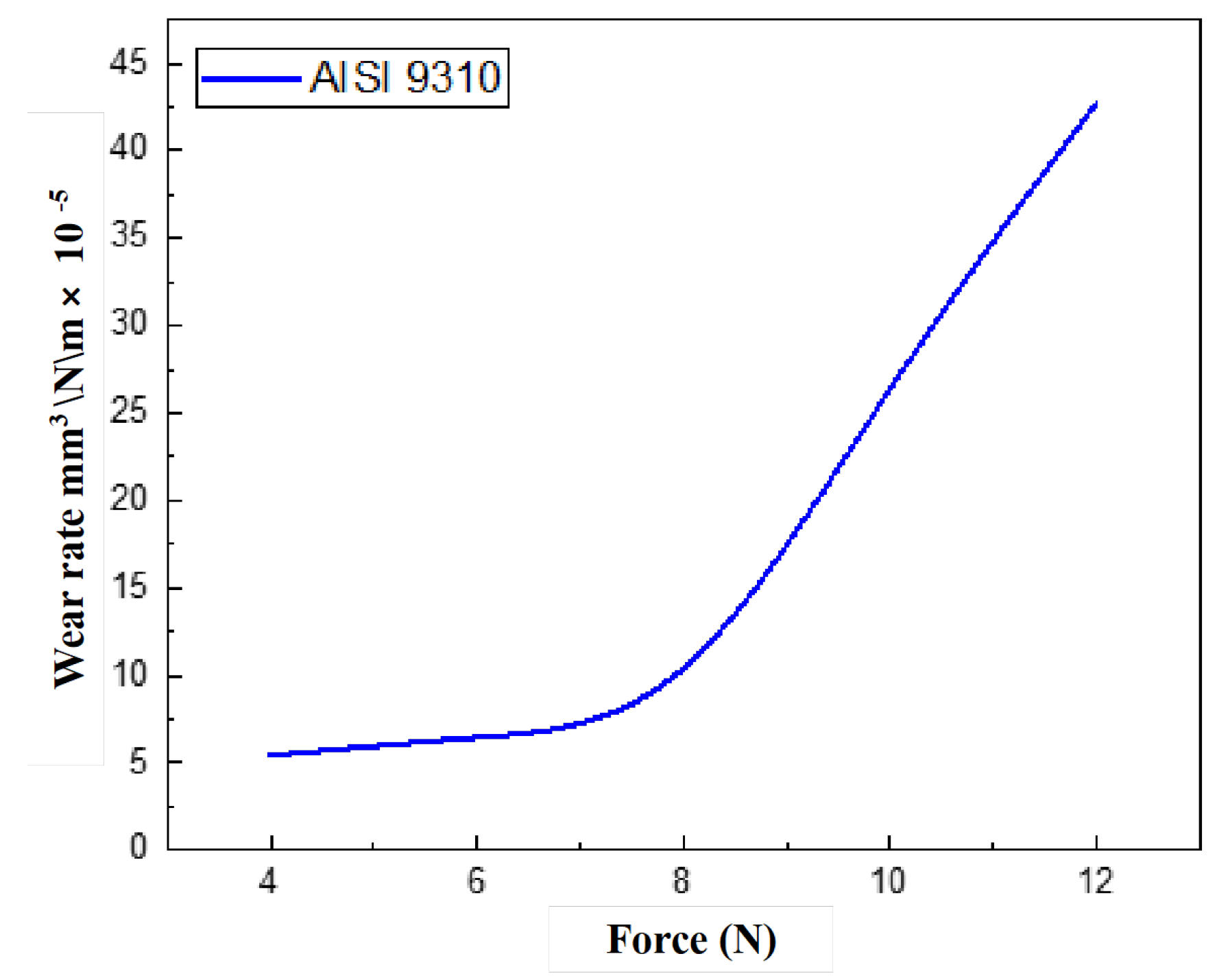
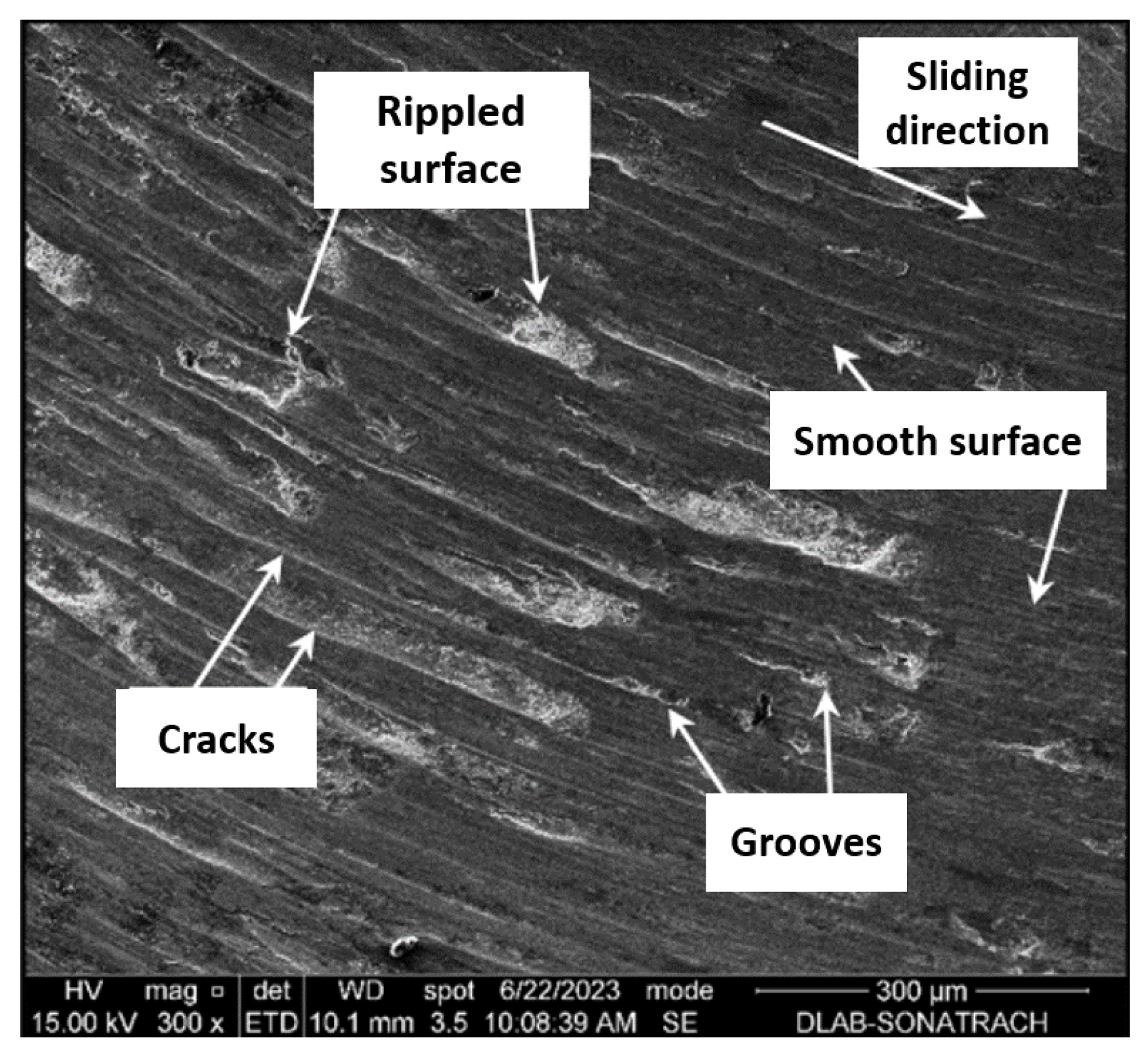
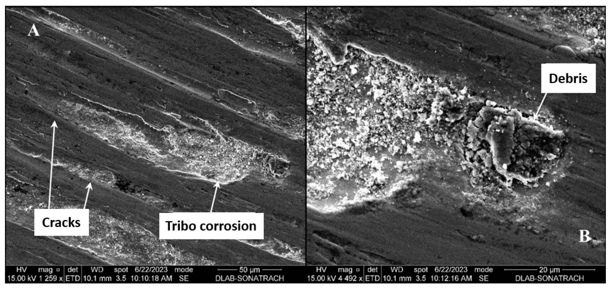
4.2.3. Wear Resistance
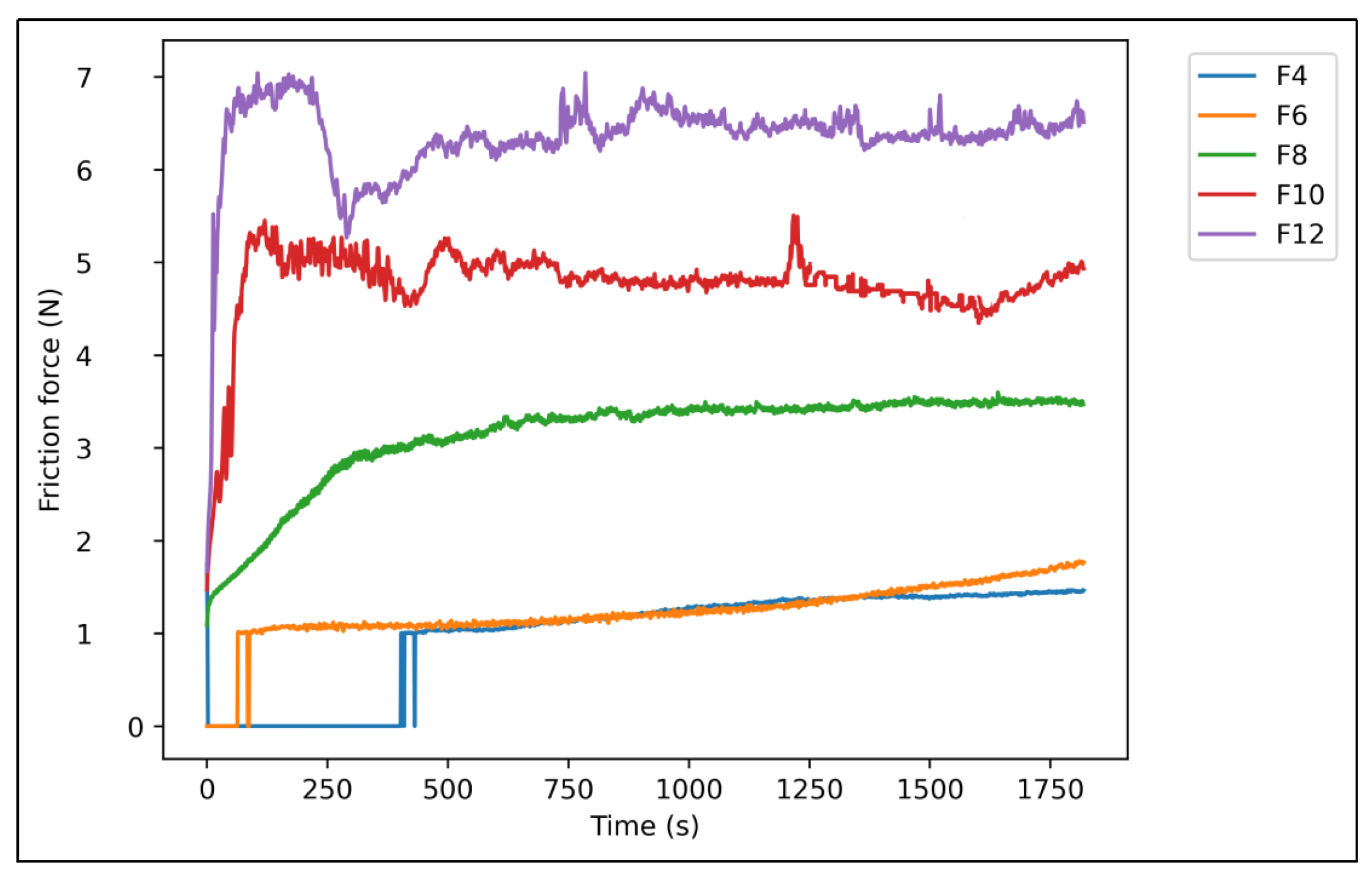
Friction Force
Frictio Coefficient
Profilometer Wear Analysis
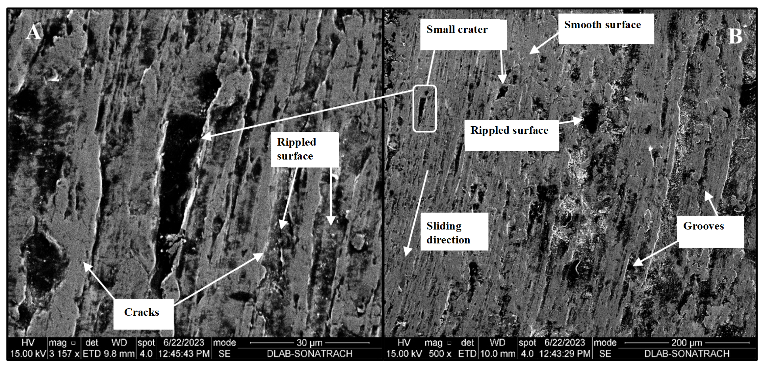
SEM Wear Characterization
4.3. The Thrust Pin: AISI 9314
4.3.1. Chemical Composition
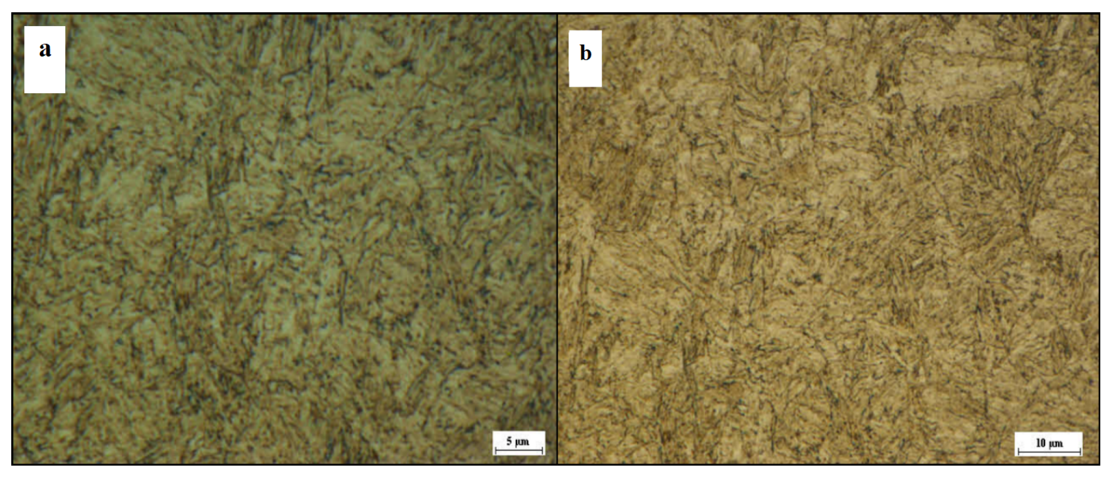
4.3.2. Optical Microstructure
4.3.3. Wear Resistance
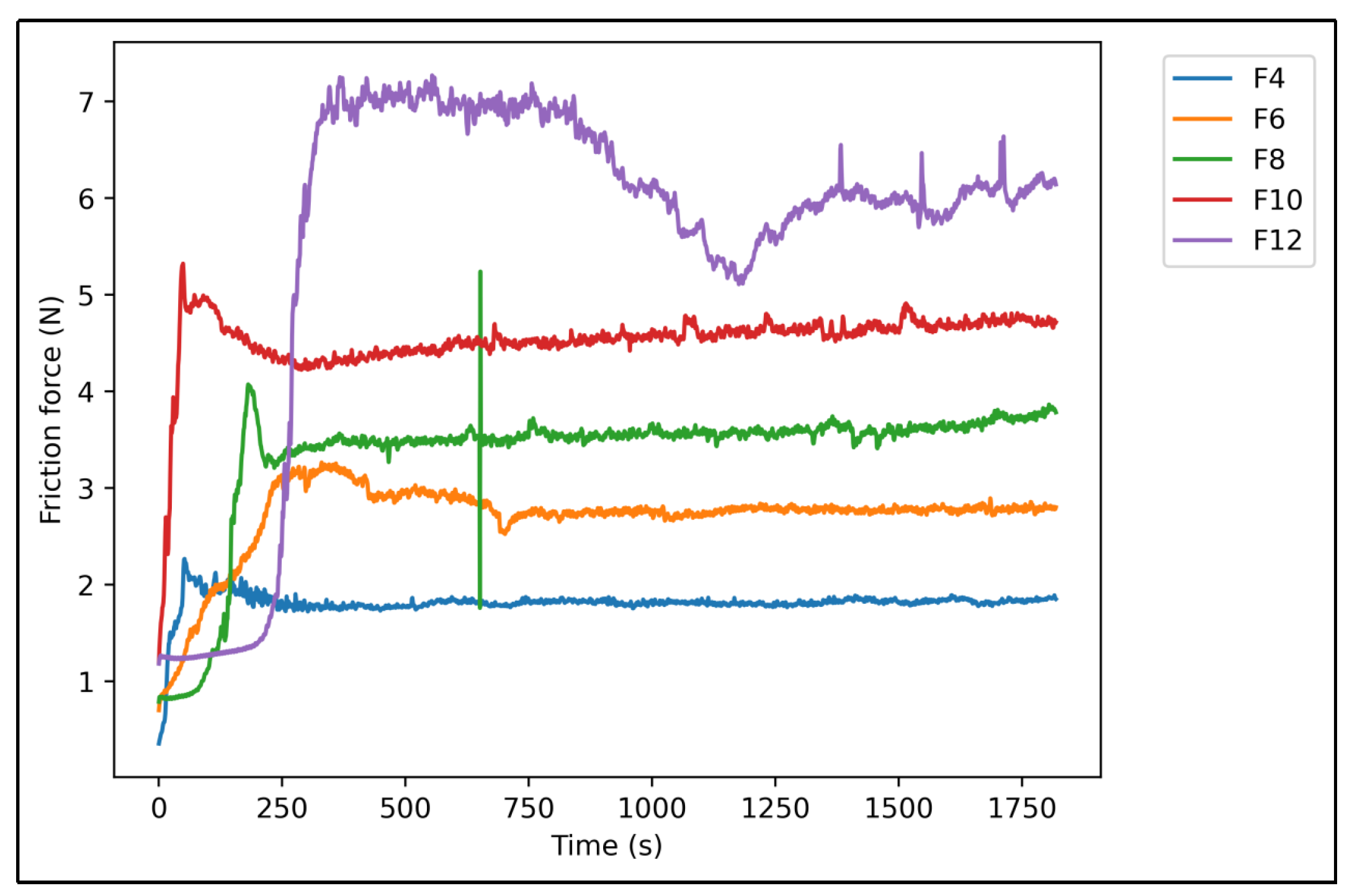
Friction Force
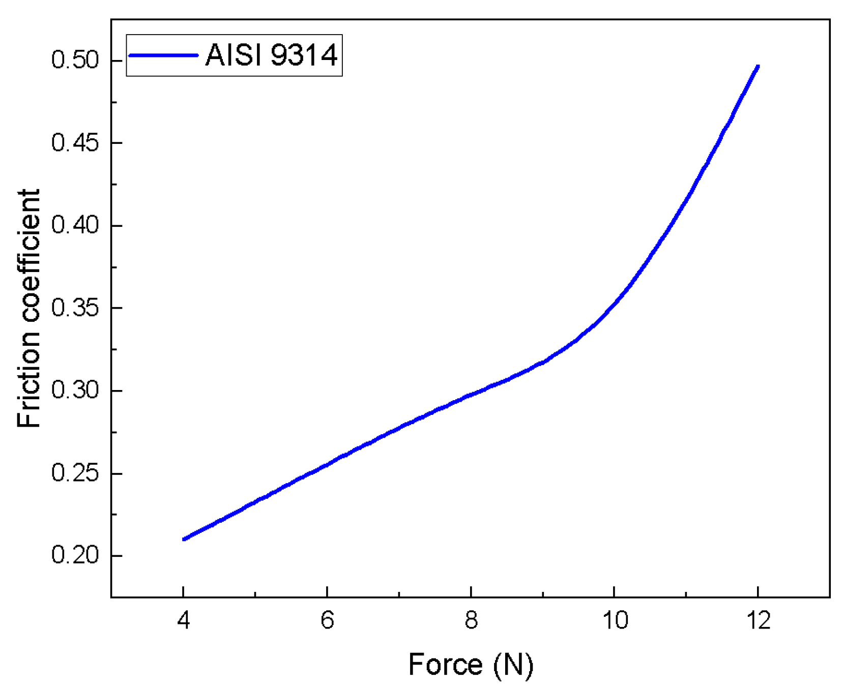
Friction Coefficient
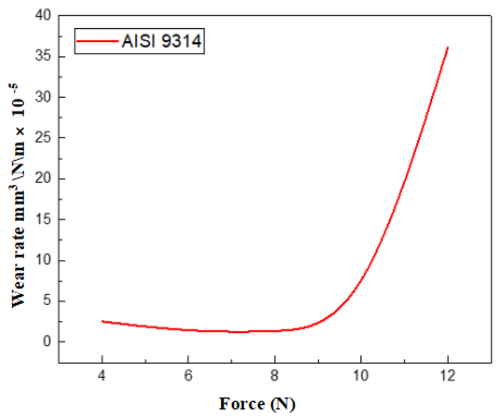
Profilometer Wear Analysis
SEM Wear Characterization
4.4. Summary of Findings and Implications
5. Conclusions
- •
- Long-term wear testing under realistic operating conditions can provide insights into the actual lifetime of these components.
- •
- Developing wear models and simulations can predict the lifetime based on wear mechanisms, drilling parameters, and material properties.
- •
- Advanced material characterization techniques, such as in situ microscopy and surface analysis, can identify critical wear parameters and failure modes.
- •
- Further research on potential surface treatments to enhance wear resistance and operational lifespan of drilling components.
- •
- Continuously exploring and developing novel steel alloys with enhanced wear resistance properties can improve component lifetimes.
Author Contributions
Funding
Institutional Review Board Statement
Informed Consent Statement
Data Availability Statement
Acknowledgments
Conflicts of Interest
References
- Ashrafizadeh, H.; McDonald, A.; Mertiny, P. Erosive and abrasive wear resistance of polyurethane liners. In Aspects of Polyurethanes; IntechOpen: London, UK, 2017. [Google Scholar] [CrossRef]
- Tremmel, S.; Marian, M. Current Trends and Applications of Machine Learning in Tribology—A review. Lubricants 2021, 9, 86. [Google Scholar] [CrossRef]
- BC Oil and Gas Commission. Oil and Gas Wells: Drilling Activity; Technical Report; BC Energy Regulator: Fort St John, BC, Canada, 2019. [Google Scholar]
- Drilling Industry Glossary|Support and Resources. (n.d.). Available online: https://www.pvisoftware.com/drilling-industry-glossary.html (accessed on 1 July 2023).
- Al-Safran, E.; Nguyen, V.T.; Nguyen, T. Theoretical modeling of Positive Displacement Motors performance. J. Pet. Sci. Eng. 2018, 166, 188–197. [Google Scholar] [CrossRef]
- Picksak, A.; John, W.; Regener, T.; Reich, M. Competitive Performance Drilling with High-Speed Downhole Motors in Hard and Abrasive Formations. In Proceedings of the IADC/SPE Drilling Conference, New Orleans, LA, USA, 23–25 February 2000. [Google Scholar] [CrossRef]
- Neelgund, R.; Smith, D.L.; Blackman, W.; Li, F. Drilling Dynamics Measurements on Positive Displacement Motors pdm Enhance Performances and Reliability. In Proceedings of the International Petroleum Technology Conference, Beijing, China, 26–28 March 2019. [Google Scholar] [CrossRef]
- Halwani, M.; Swart, D.; Muthusamy, R.; Almaskari, F.; Zweiri, Y.; Ayyad, A. Neuromorphic vision based control for the precise positioning of robotic drilling systems. Robot. Comput.-Integr. Manuf. 2023, 79, 102419. [Google Scholar] [CrossRef]
- Hoteit, H.; Albattat, R. A semi-analytical approach to model drilling fluid leakage into fractured formation. Rheol. Acta 2021, 60, 353–370. [Google Scholar] [CrossRef]
- Von Gynz-rekowski, G.H.; Bolejack, D.E.; Herben, W.C. Mud Motor Bearing Assembly and Method. U.S. Patent No. 9,267,539, 23 February 2016. Available online: https://www.freepatentsonline.com/9267539.html (accessed on 15 July 2023).
- Drilling Motor Handbook, Volume 2. Scientific. 2018. Available online: https://www.scribd.com/document/501657996/2018 (accessed on 15 July 2023).
- Drilling Mud Motor Components Operations. Drilling Manual. 2017. Available online: https://www.drillingmanual.com/downhole-drilling-mud-motors-components-diagram/ (accessed on 20 July 2023).
- Kecibas, G.; Besirova, C.; Chehrehzad, M.R.; Burun, G.; Pehlivan, T.; Uresin, U.; Emekli, E.; Lazoglu, I.; Bilgili, D. Tool flank wear prediction using high-frequency machine data from industrial edge device. Procedia CIRP 2023, 118, 483–488. [Google Scholar] [CrossRef]
- Holmberg, K.; Kivikytö-Reponen, P.; Härkisaari, P.; Valtonen, K.; Erdemir, A. Global energy consumption due to friction and wear in the mining industry. Tribol. Int. 2017, 115, 116–139. [Google Scholar] [CrossRef]
- Holmberg, K.; Erdemir, A. The impact of tribology on energy use and CO2 emission globally and in combustion engine and electric cars. Tribol. Int. 2019, 135, 389–396. [Google Scholar] [CrossRef]
- Wheeler, D. Applications of diamond to improve tribological performance in the oil and gas industry. Lubricants 2018, 6, 84. [Google Scholar] [CrossRef]
- Sexton, T.; Cooley, C. Polycrystalline diamond thrust bearings for down-hole oil and gas drilling tools. Wear 2009, 267, 1041–1045. [Google Scholar] [CrossRef]
- Vakis, A.I.; Yastrebov, V.; Scheibert, J.; Nicola, L.; Dini, D.; Minfray, C.; Almqvist, A.; Paggi, M.; Lee, S.; Limbert, G.; et al. Modeling and simulation in tribology across scales: An overview. Tribol. Int. 2018, 125, 169–199. [Google Scholar] [CrossRef]
- Dzaky, D.M.; Aziz, A.; Saefulloh, I.; Susilo, S.; Hasanah, I.U. Rancang Bangun Chasis Pin Holder Pada Tribometer Pin On Disc Berbasis Modifikasi Pada Mesin Bubut Konvensional. JPTM J. Pendidik. Tek. Mesin 2021, 8, 173–179. [Google Scholar] [CrossRef]
- Böttcher, R.; Winkler, H.; Dienwiebel, M.; Scherge, M. Tribology of Wire Arc Spray Coatings under the Influence of Regenerative Fuels. Lubricants 2018, 6, 60. [Google Scholar] [CrossRef]
- Ahmer, S.M.H.; Khan, N.; Shah, S.I.A.; Jan, L.S. Experimental results of the tribology of aluminum in the presence of polytron additive. In Friction, Lubrication and Wear; IntechOpen: London, UK, 2019. [Google Scholar] [CrossRef]
- Viña, J.; García, M.C.; Castrillo, M.Á.B.; Viña, I.; Argüelles, A. Wear behavior of a glass Fiber-Reinforced PEI composite. J. Thermoplast. Compos. Mater. 2008, 21, 279–286. [Google Scholar] [CrossRef]
- Bill, R.C. Fretting of AISI 9310 steel and selected Fretting-Resistant surface treatments. Tribol. Trans. 1978, 21, 236–242. [Google Scholar] [CrossRef]
- Hartley, N.E.W.; Hirvonen, J. Wear testing under high load conditions. Nucl. Instruments Methods Phys. Res. 1983, 209–210, 933–940. [Google Scholar] [CrossRef]
- Yan, H.; Wei, P.; Su, L.; Liu, H.; Wang, D.; Zhang, X.; Deng, G. Rolling-sliding contact fatigue failure and associated evolutions of microstructure, crystallographic orientation and residual stress of AISI 9310 gear steel. Int. J. Fatigue 2023, 170, 107511. [Google Scholar] [CrossRef]
- Ganechari, S.M.; Kabadi, V.R.; Kori, S. Study of Surface Roughness and Hardness of Low Carbon Nickel-Chromium Based Alloy Steels under High Temperature (AISI sae8630, 3140 and 9310). In Proceedings of the ICWET’11 International Conference and Workshop on Emerging Trends in Technology, Mumbai, Maharashtra, India, 25–26 February 2011. [Google Scholar] [CrossRef]
- Li, X.; Zhou, L.; Zhao, T.; Pan, X.; Liu, P. Research on Wear Resistance of AISI 9310 Steel with Micro-Laser Shock Peening. Metals 2022, 12, 2157. [Google Scholar] [CrossRef]
- Hegadekatte, V.; Kurzenhäuser, S.; Huber, N.; Kraft, O. A predictive modeling scheme for wear in tribometers. Tribol. Int. 2008, 41, 1020–1031. [Google Scholar] [CrossRef]
- Suresh, R.; Kumar, M.; Basavarajappa, S.; Kiran, T.; Yeole, M.; Katare, N. Numerical Simulation Experimental study of wear depth and Contact pressure distribution Of Aluminum MMC Pin on Disc Tribometer. Mater. Today Proc. 2017, 4, 11218–11228. [Google Scholar] [CrossRef]
- ASTM E415; Standard Test Method for Analysis of Carbon and Low-Alloy Steel by Spark Atomic Emission Spectrometry. ASTM International: West Conshohocken, PA, USA, 2015.
- ASTM E407; Standard Practice for Microetching Metals and Alloys. ASTM International: West Conshohocken, PA, USA, 2007.
- ASTM E18; Standard Test Methods for Rockwell Hardness of Metallic Materials. ASTM International: West Conshohocken, PA, USA, 2020.
- ASTM E384; Standard Test Method for Microindentation Hardness of Materials. ASTM International: West Conshohocken, PA, USA, 2022.
- ISO 7148; Plain Bearings—Testing of the Tribological Behavior of Bearing Materials. International Organization for Standards: Geneva, Switzerland, 2012.
- ASTM E1508; Standard Guide for Quantitative Analysis by Energy-Dispersive Spectroscopy. ASTM International: West Conshohocken, PA, USA, 2019.
- Karia, P. SAE—AISI 9310 Alloy Steel—Properties, Composition and Uses. The Piping Mart Blog. Available online: https://tinyurl.com/msmhv7b7 (accessed on 5 May 2023).
- Li, X.; Tandon, K.N. Microstructural characterization of mechanically mixed layer and wear debris in sliding wear of an Al alloy and an Al based composite. Wear 2000, 245, 148–161. [Google Scholar] [CrossRef]
- Lim, S.; Brunton, J.H. A dynamic wear rig for the scanning electron microscope. Wear 1985, 101, 81–91. [Google Scholar] [CrossRef]
- Stachowiak, G.; Batchelor, A.W. 13—Corrosive and Oxidative Wear, Engineering Tribology, 3rd ed.; Butterworth-Heinemann: Oxford, UK, 2005; pp. 573–593. ISBN 9780750678360. [Google Scholar]
- Lee, T.; Mathew, E.V.; Rajaraman, S.; Manivasagam, G.; Singh, A.K.; Lee, C.S. Tribological and corrosion behaviors of warm- and hot-rolled Ti-13Nb-13Zr alloys in simulated body fluid conditions. Int. J. Nanomed. 2015, 2015, 207. [Google Scholar] [CrossRef]
- Steel Grades. (n.d.). Datasheet for Steel Grades Carbon Steel AISI E9314. Available online: https://tinyurl.com/4xffb4f2 (accessed on 20 July 2023).
- Prathipati, R.; Dora, S.P.; Chanamala, R. Wear behavior of wire electric discharge machined surface of 316L stainless steel. SN Appl. Sci. 2020, 2, 412. [Google Scholar] [CrossRef]
- Karaoğlu, S. Structural characterization and wear behavior of plasma-nitrided AISI 5140 low-alloy steel. Mater. Charact. 2002, 49, 349–357. [Google Scholar] [CrossRef]


| Chemical Element (% Mass) | 526.13 HV Area | 426.12 HV Area |
|---|---|---|
| Fe | 88.67 | 89.26 |
| C | 5.5 | 5.05 |
| Ni | 3.47 | 3.38 |
| Cr | 1.42 | 1.45 |
| Si | 0.93 | 0.86 |
| Steel | Content of Elements [Mass %] | |||
|---|---|---|---|---|
| C | Ni | Cr | Mo | |
| Insert | 0.1 | 3.15 | 1.29 | 0.063 |
| AISI 9310 | 0.08–0.13 | 3.00–3.50 | 1.00–1.40 | 0.08–0.15 |
| Variable | Yield Strength R0.2 | Tensile Strength Rm | Elongation at Fracture A% | Elastic Modulus E | Rockwell Hardness |
|---|---|---|---|---|---|
| Value | 900 MPa | 1068 MPa | 15.50% | 200 GPa | 36 |
| Spot Number | ||||||
|---|---|---|---|---|---|---|
| 1 | 2 | 3 | 4 | 5 | ||
| Chemical elements [mass %] | Fe | 48.39 | 80.52 | 55.55 | 46 | 61.37 |
| C | 30.73 | 14.48 | 13.4 | 15.87 | 18.39 | |
| Cr | 1.4 | 1.24 | 1.09 | 0.89 | 1.27 | |
| Ni | 2.31 | 2.97 | 2.2 | 2.34 | 2.72 | |
| O | 7.22 | / | 27.04 | 33.45 | 15.59 | |
| N | 4 | / | / | / | / | |
| Cl | 0.76 | / | / | 0.8 | / | |
| K | 0.86 | / | / | / | / | |
| Ca | 1.3 | / | / | / | / | |
| Si | 0.76 | 0.78 | 0.72 | 0.65 | 0.66 | |
| Na | 1.45 | / | / | / | / | |
| S | 0.82 | / | / | / | / | |
| Steel | Content of Elements [Mass %] | |||
|---|---|---|---|---|
| C | Ni | Cr | Mo | |
| Pin | 0.13 | 3.35 | 1.28 | 0.064 |
| AISI 9314 | 0.11–0.17 | 3.00–3.50 | 1.00–1.40 | 0.08–0.15 |
| Variable | Yield Strength R0.2 | Tensile Strength Rm | Elongation at Fracture A% | Elastic Modulus E | Rockwell Hardness |
|---|---|---|---|---|---|
| Value | 1034 MPa | 1158 MPa | 15% | 190–210 GPa | 41 |
Disclaimer/Publisher’s Note: The statements, opinions and data contained in all publications are solely those of the individual author(s) and contributor(s) and not of MDPI and/or the editor(s). MDPI and/or the editor(s) disclaim responsibility for any injury to people or property resulting from any ideas, methods, instructions or products referred to in the content. |
© 2024 by the authors. Licensee MDPI, Basel, Switzerland. This article is an open access article distributed under the terms and conditions of the Creative Commons Attribution (CC BY) license (https://creativecommons.org/licenses/by/4.0/).
Share and Cite
Benarbia, A.; Tomomewo, O.S.; Laalam, A.; Khalifa, H.; Bertal, S.; Abadli, K. Enhancing Wear Resistance of Drilling Motor Components: A Tribological and Materials Application Study. Eng 2024, 5, 566-588. https://doi.org/10.3390/eng5020032
Benarbia A, Tomomewo OS, Laalam A, Khalifa H, Bertal S, Abadli K. Enhancing Wear Resistance of Drilling Motor Components: A Tribological and Materials Application Study. Eng. 2024; 5(2):566-588. https://doi.org/10.3390/eng5020032
Chicago/Turabian StyleBenarbia, Achouak, Olusegun Stanley Tomomewo, Aimen Laalam, Houdaifa Khalifa, Sarra Bertal, and Kamel Abadli. 2024. "Enhancing Wear Resistance of Drilling Motor Components: A Tribological and Materials Application Study" Eng 5, no. 2: 566-588. https://doi.org/10.3390/eng5020032