Abstract
The main objective of this work is to present a comprehensive and integrated methodology to enhance the resilience of transportation critical infrastructure (TCI), focusing on the interplay between geotechnical assets and the transport network. Societies are greatly dependent on transport infrastructure systems, and as the mobility of passengers and the transport of freight is continuously growing, a disruption due to natural or man-made hazards creates significant impacts and dysfunctionalities on their operation and necessitates response measures to minimize vulnerability and ensure continuous functionality and robustness through resilience. Therefore, resilience quantification allows the design of ad hoc operation action plans before, during, and after a disruption, considering the dynamics of societal, ecological, and technological (SET) environments. The current work focuses on resilience quantification methodologies for TCIs and on the influence of single geotechnical asset (i.e., slope failure) resilience capacity on the overall system (i.e., national road network) resilience. Two case studies of unexpected transport network disruptions that took place in Greece are presented, and resilience metrics and performance indicators are applied to quantify the influence of the recovery stage.
1. Introduction
The effective maintenance of vital societal functions for basic services (e.g., food, energy, healthcare, communications, and transportation of freight and passengers) depends greatly on the operation and protection of the critical infrastructures (CIs). Critical infrastructure is considered “an asset, a facility, equipment, a network or a system, or a part of an asset, a facility, equipment, a network or a system that is necessary for the provision of an essential service” [1]. Internationally, energy (e.g., European Network of Transmission System Operators, ENTSO-E) and the transport (e.g., Trans-European Transport Network, TEN-T in [2]) sectors are among the two important types of CI [3,4,5]. The damage or destruction of CI assets and the subsequent system (e.g., road network for transport) disruption due to natural hazards, terrorism, criminal activity, or malicious behavior may have a significant negative impact on the security of the EU and the well-being of its citizens (https://www.critical-entities-resilience-directive.com, accessed on 7 May 2024). The CI must satisfy the cross-cutting criteria of casualties (potential number of fatalities or injuries), economic effects (economic loss, degradation of services/products, environmental effects), and public effects (public confidence, physical suffering, disruption of daily life, loss of essential services), as well as any sectoral criteria that consider the characteristics of every CI sector [3].
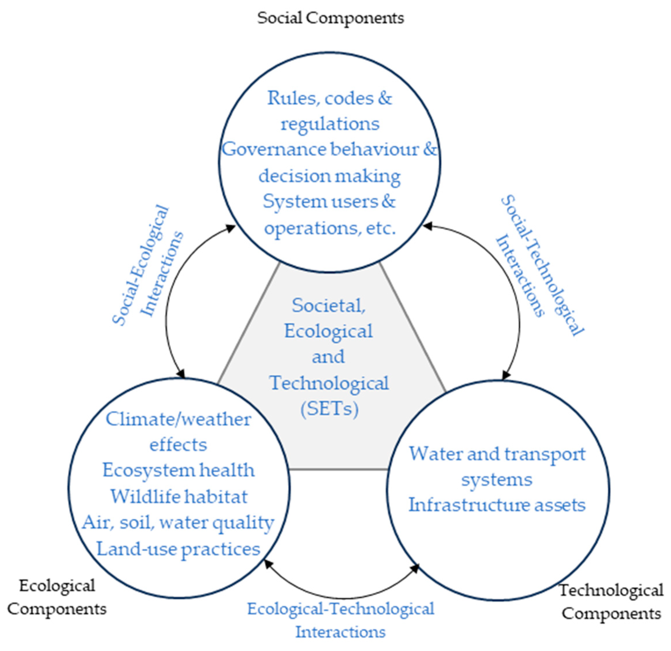
The above essential functions and services shall be provided by the transportation critical infrastructures (TCIs), as discussed in the current paper, and can be approached through the framework of societal, ecological, and technological (SET) environments (Figure 1). Typical TCI assets are bridges, embankments, cut slopes, and tunnels, which must be designed, built, and maintained according to rigorous standards ([6]) so that (a) the risk exposure remains at an acceptable/manageable level; and (b) sustainability, the ability to survive in the long run in an acceptable operational condition, is ensured.
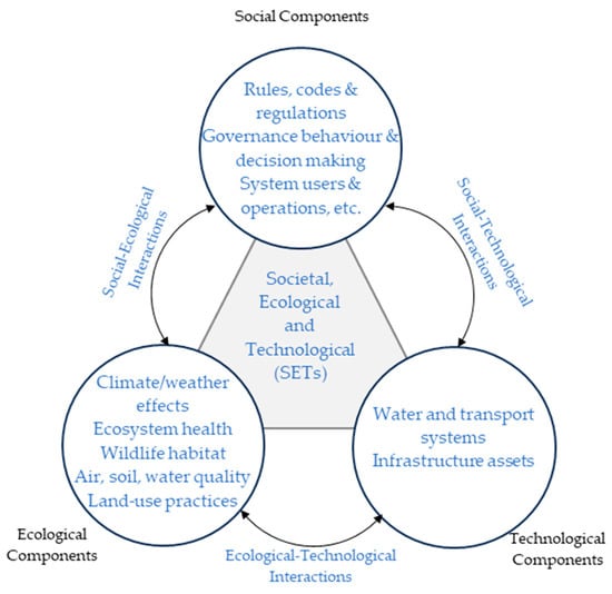
Figure 1.
Framing infrastructure as social, ecological, and technological systems (based on [7]).
Notably, the United Nations classifies 90% of disasters as “weather- and climate-related” or “man-made” [8,9]. Concerning “weather- and climate-related” disasters, the design return period of extreme rainfall for about 45% of infrastructure is expected to decrease by at least 25% according to [10]. Further considering the alarming surge in Climate Change between 2011 and 2020 [11], it becomes apparent that nowadays TCIs are more exposed to extreme and unpredictable events, which may worsen in the next decades. As TCIs are exposed to this evolving adverse environment, in which natural and man-made hazard events continuously increase in quantity and intensity, it is vital to ensure that existing (often aged/degraded) as well as new TCI assets and systems are capable of withstanding, adapting to, and recovering from their exposure condition, in other words, to be dynamically resilient. This is also implied by the new EN 1990 Structural and Geotechnical Design, which demands robustness as one of the structure’s reliability design criteria.
In that sense, resilience herein is broadly defined as the ability of a system to adjust its functionality in the presence of a disturbance and unpredicted change and maintain its “modus operandi” during its life cycle. Thus, the resilience ability can be seen as a prerequisite for sustainability. This ability is analyzed in relation to robustness, resourcefulness, redundancy, and rapidity [12] and it also needs to consider the integral of the reactive absorptive and reactive capacity [13]. Considering that resilience strengthening stands between risk mitigation and sustainability [14] of TCIs, any state-of-the-art TCI operational management approach must employ an integrated Risk–Resilience–Sustainability (RRS) framework [15]. Because risk, resilience, and sustainability are usually approached qualitatively, reliable decision-making operational management tools require quantification methodologies for all RRS individual components.
Following this approach, this paper focuses on resilience quantification methodologies for TCIs and specifically on the influence of the single geotechnical asset (i.e., slope failure) resilience capacity on the overall system (i.e., national road network) resilience. It represents the basis for geospatial (i.e., multiple) asset resilience management on overall network resilience management as part of an integrated RRS. These principles for the quantification of resilience of TCIs due to dynamic adverse environmental exposure are examined within a SET system point of view, and the interaction of resilience with risk is also presented. This work is part of an ongoing research work on a quantified RRS framework for civil engineering infrastructure.
This paper is structured as follows: Section 1 introduces the framework; Section 2 presents the impact of the societal, ecological, and technological environment on CTI risk; and Section 3 describes the transportation resilience at the network and asset scale, providing the resilience metrics and quantification methodology. In Section 4, two case studies of unexpected events in Greece are used to quantify the influence of the recovery stage, and the results of their resilience response are presented. The last section presents the conclusions of the applied methodology.
2. The SET Influence on TCI Risk
Within a SET system approach, the potential hazard is the adversity of the environment acting on the (geotechnical) engineering structure. Hazard is any unexpected, extreme, or seasonal adverse event that can interrupt the seamless operation and reliability of the TCI, being either man-made (e.g., terrorist attacks, explosions, malfunction of secondary infrastructure) or natural (e.g., extreme weather conditions, earthquakes). These have been classified as multi-hazards and emerging hazards [16] and are among the hazards of greatest interest within European countries. Adversity corresponds to a persistent or transient condition of a certain uncertainty (see [17]).
TCIs operate within evolving SET environments, while each SET component affects the TCIs’ robustness. Moreover, it is the response of TCI’s single asset or set of assets in the transport network that manifests the performance of the complete transport system response and ensures its seamless operation. However, sometimes, the TCI assets, including geotechnical ones (e.g., slopes, embankments, retaining walls, and tunnels), are not as robust as they might look from a distance, which mainly relates to the
- Inability during their design of (a) capturing a realistic response of the specific structure or of the total system; and (b) foreseeing adverse conditions (hazards) to which the structure or system will be exposed.
- Inability during their operation of (a) identifying vulnerable assets and (b) maintaining and observing them properly.
There are known hazards (e.g., rainfall, wildfire, etc.), which can be quantified through known statistical measures (for probability) or unknown statistical measures (for likelihood) and correspond to the known or known/unknown. The changing weather and climate can trigger mechanisms, such as seasonal pore pressure changes, that enhance the deterioration (which reduces safety) of transport infrastructure earthworks (cut slopes and embankment slopes) [18]. For natural hazards, once their underlying processes are determined and sufficient field data are collected, a better understanding of the phenomena is achieved, and their likelihood can be treated more effectively, from unknown to a known probability. There are also known man-made hazards, which usually have an unknown likelihood (known/unknown cases of risk), but once they occur, they have a negative impact on the TCI, which needs to be quantified. These cases, as well as unknown hazards of an unknown probability, must be considered through a resilience analysis.
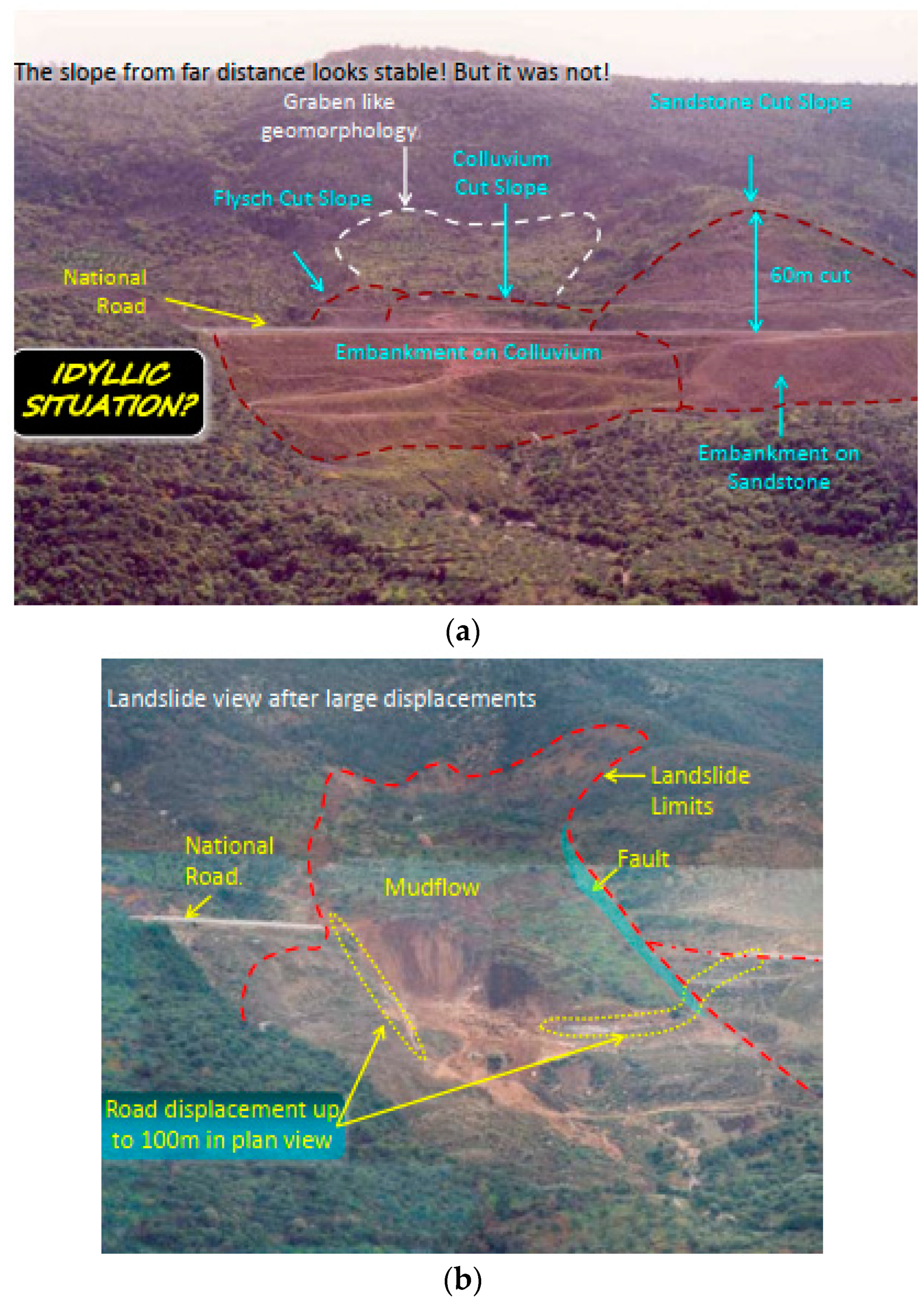
For instance, the ecological SET component exposes assets to known hazards (e.g., rainfall) and threats (e.g., landslides) of a known or unknown hazard probability. Figure 2 presents two instances of a slope failure case study [19] typical of such a situation. Figure 2a corresponds to an unstable state in 2001, seemingly stable from a distance, before the onset of the major instability. Although signs of instability were visible on the pavement, the extent of the unstable area that extended well beyond the road level was identified only after an expert in situ investigation along the road and the uphill and downhill slopes. Obviously, this directly relates to the impact of the associated hazard, as the larger the unstable area, the greater the impact. On the other hand, during the design and construction phase in the 1990s, the risk of failure could only be suspected by the surface depression on the geomorphology (that resembles a geological graben) based on the assessment of the topographic maps and of the view from the opposite side of the gorge (Figure 2a), which requires the opinion of an expert. In 2003, the slope exposure to one of the highest precipitations of the past 50 years for over a three-month period led to a catastrophic failure in which the faults bounding the graben lightened by day (Figure 2b). This is an example of how the ecological SET component affects the technological one and, as will be further analyzed, how the asset failure affects the network operation.
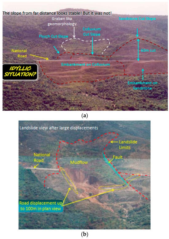
Figure 2.
SET environment interaction due to ecological component; case of Tsakona area (in Greece) landslide: (a) prior onset of major activation and (b) after major activation (based on [18]).
For decision-making purposes, resilience against an adverse condition (threat) like the aforementioned (i.e., landslide activation) requires knowing whether this condition is foreseeable (known hazard) and its likelihood (known probability), as well as quantifying its impact on the TCI and finally the TCI performance. Performance quantification at the asset level (e.g., slope) relates to the extent of the destruction/deterioration and at the system level to the extent of the system dysfunctionality (e.g., road network). It includes time evolution and, thus, the ability of the asset/system to respond and recover to a functional situation after the shock event. Any asset destruction/deterioration affects the system’s functionality and jointly relates to the overall transport network’s resilience, ability, and capacity.
The societal SET component may expose TCIs to known or unknown threats, e.g., the dynamics of social and economic development, and can be considered a known/unknown probability. For instance, urban development and extreme rainfall can affect slope stability, which happened in Funchal ([20,21]), which in turn may deteriorate the operational capability of road and public utility networks, not only buildings. Another example is the landslide at the Pisouri residential area in Cyprus (see also [22]), in which it can be argued that the land use change resulted in the development of the instability phenomenon. The mechanism remains to be defined. A societal component is also the increase in traffic, which leads to greater users’ exposure to the hazards and a TCI failure that affects consequences.
Finally, the technological component, e.g., damage to public utility assets/systems, within the TCI’s asset zone of influence, may also result in asset destruction/deterioration. A constant leakage from the sewage system and subsequent dirt water infiltration may gradually result in slope instability phenomena, as could have been the case with the landslide in the residential area of Cumpăna in Romania. This can be considered a known hazard of an unknown probability that needs to be examined to determine its effects. The “unknown” hazards and “unknown” probabilities represent our inability to fully capture the risks of a TCI. To dig out these “unknowns”, we need to integrate the structure (asset) within its complete social–economical–technological (SET) environment.
Therefore, in the analysis and the design of a TCI, the operating SET environment and its evolution must be determined, both at the asset scale (e.g., geo-structure, building, bridge) and at the network scale (e.g., road network). In this perspective, the following aspects, which relate to risk but do not address sufficient resilience, need an answer:
- Identify potential hazards (hazard threats) and their associated threats that could disrupt transport network operations, and estimate their likelihood and evolution over time.
- Determine the level of damage (apart from geotechnical ones; also identify potential travel time delays, supply chain disruptions [23], rerouting, etc.) against the recognized threats due to the hazard exposure and the corresponding cascading effects (hazard vulnerability and consequences).
- Determine the required remediation actions to prevent or repair damage (hazard vulnerability and consequences) and formulate strategies to manage risks (e.g., route optimization, general cost minimization, etc.).
The typical risk (R) quantification is given by Equation (1), where H is the hazard exposure probability (uncertainty), V is the vulnerability to the hazard (damage), and C is the consequence (cost in terms of repair and lives) if damaged by the hazard. The higher the risk, the greater the potential for loss, which can be used as a tool to decide if resilience needs consideration. While risk (cumulative or instant) relates to a single shock event, resilience addresses the post-shock TCI performance evolution, even if the hazard’s occurrence likelihood is unknown.
R = H × V × C,
3. Materials and Methods
A TCI consists of the road and/or the railway network and the assets (e.g., tunnels, bridges, embankments, and natural and cut slopes). All assets assist in the seamless operation of the entire network, so resilience needs to be examined [16] with respect to the interaction of
- “Hard” resilience: the resilience capacity of and response enhancement in an asset (i.e., structural integrity, micro-scale).
- “Soft” resilience: the resilience capacity of the transport network and its management enhancement (i.e., traffic efficiency, meso-scale, macro-scale).
The complete chain from natural or man-made hazard identification to the resulting cascading effects, the associated threat, and, finally, the resilience impact needs consideration. An example is presented in Table 1, in which landslides and floods, often identified as hazards, correspond to resulting threats since they cannot exist alone but are the result of a natural or man-made disturbance to the system’s overall stability.

Table 1.
An example of hazard–threat–resilience impact identification of assets and networks [16].
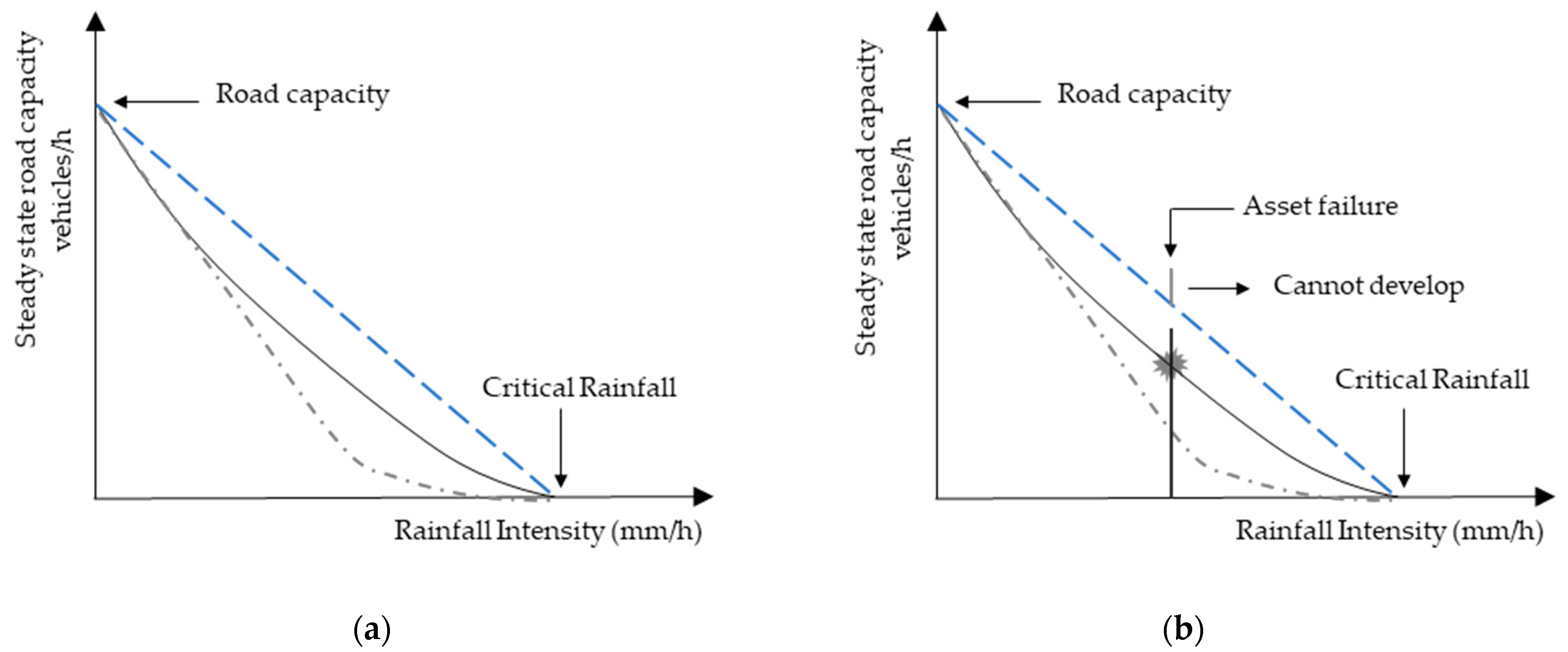
Depending on the nature of the threat, the impact on the network may be recoverable or irrecoverable, depending also on the asset’s response described later. Figure 3 presents the road traffic response regarding rainfall intensity, or cumulative rainfall. Assuming no asset failure, an increasing rainfall intensity reduces the steady-state road capacity down to zero for a critical rainfall (Figure 3a). However, the asset may fail depending on the previous cumulative rainfall, which disrupts network operation (Figure 3b). The following two situations can be distinguished, which both may result in system failure:
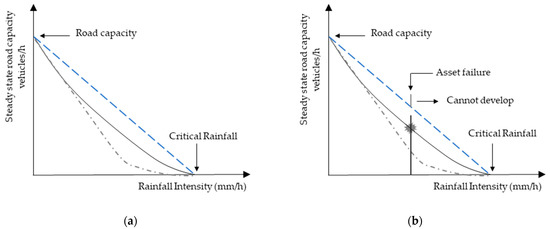
Figure 3.
Network response: “real” (continuous) and idealized (dashed) steady-state responses—(a) assets under operation, (b) assets under failure.
- A short period of heavy rainfall (hazard) may result in an increase in river and stream flow (cascading effect), which in turn leads to road floods (asset threat and response) and the disruption of the road network operation (network threat and response; see Table 1). If the asset remains intact, the traffic efficiency is fully recoverable after the rainfall. The critical measurable index is the rainfall intensity over a nominally short period of time. A hydraulic engineering analysis is required for the identification of possible risk hotspots.
- A long period of steady rainfall (hazard) may result in an increase in infiltration, piezometric water level (underground), and pore water pressure (cascading effect), which in turn leads to slope failure (asset threat and response) and the disruption of the road network operation (network threat and response; see Table 1). The network’s traffic efficiency is non-recoverable unless remediation works are performed on the failed assets (work input). For slope stability, a critical measurable index is the pore water pressure, which is related to cumulative rainfall over a nominally long period of time. For instance, [24] has presented the influence of previous cumulative rainfall on slope movements. A geotechnical engineering analysis is required for the identification of possible risk hotspots.
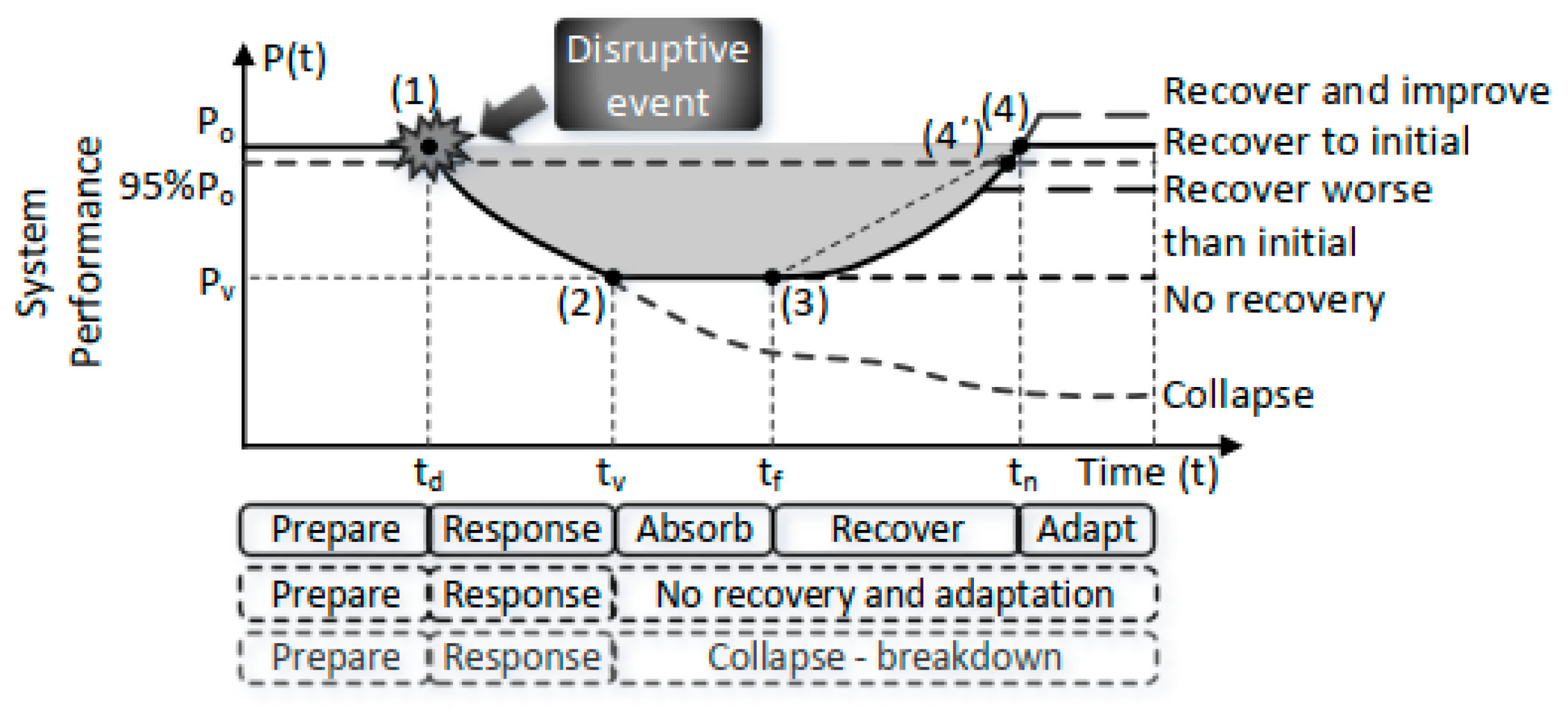
Figure 3b does not account for the full/partial/non-recoverability of the traffic efficiency due to the asset’s damage/failure and its subsequent response. For a damaged asset, it is critical to know if the traffic response is recoverable and, if it is not, it is critical then to determine the work input required (in terms of cost and time) to bring the road operation to a specific desired efficiency. Based on the approach presented by [25], the following general stages can be identified during the resilience response of the system (network and asset) (see Figure 4, also [16]), where td is the disruptive event occurrence time, tv is the end of the response time representing the lower attainable or acceptable performance (Pv), tf is the end of the lower performance period, and tn is the time to recover in a revised acceptable performance:
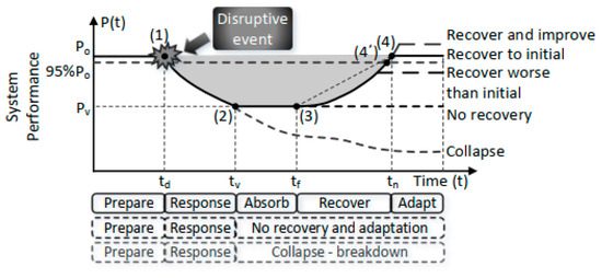
Figure 4.
A representation of the complete resilience response via system performance [16].
- Stage 1: Reliability. The system is in a steady state of complete operation (performance equal to Po) before the occurrence of an extreme, possibly unexpected, adverse event (anticipation–preparedness).
- Stage 2: Degradation. The system’s operation diminishes continuously, path (1)–(2) (response).
- Stage 3: Disruption. The system’s operation is disrupted or under-functioning, path (2)–(3) (absorb).
- Stage 4: Recovery. The system’s operation improves towards a steady-state condition, path (3)–(4) (recovery).
- Stage 5: Adaptation. The system is in a steady-state condition (adapt).
Some stages (e.g., 2 and 4) may not develop fully, while the adapted performance (i.e., after recovery) is not necessarily the same as during anticipation. The variation of the system performance curve with time represents the resilience curve, which can be used for the quantification of resilience.
In this work, the network resilience is examined through case studies: vulnerable assets have failed and have disrupted and altered the network operation, and then have been remediated, an action that restored network operation.
Resilience is generally described through the asset’s time evolution performance (hard resilience [16]) of the absorb–respond–recover–adapt path. A basic concept to maximize resilience is to minimize the performance loss area (shaded area in Figure 4).
Resilience Metrics and Quantification
The authors from [24] highlighted the need for the standardization of engineering quantification metrics in diverse engineering disciplines and categorized two resilience quantification metrics: (a) deterministic versus probabilistic and/or (b) static versus dynamic. Resilience metrics are presented based on the resilience curve (Figure 4) as well as the pre- and post-disruption performances, reliability and restoration. Resilience metrics can be determined from the resilience curve, resulting in metrics for the asset or the system of resilience capability individual characteristics (e.g., [26]) in case the curve is a continuous function.
Vulnerability may be represented by the severity impact on the performance (e.g., damage degree, losses on safety, and traffic capacity), or in other words, the instantaneous system performance (IP), described by the absolute drop (Equation (2a), [25]) or the normalized drop (Equations (3a) and (4a) [24]), where Po is the initial–typical performance, Pv is the performance after the disruption, and Pmin is the minimum possible performance. The lower the IP, the higher the impact. Equations (2b), (3b), and (4b) correspond to the cases in which underperformance occurs when Pv increases. For evaluating the instant performance, Equation (4a) is easier to use, as it takes values from 1 (maximum performance) to 0 (total disruption). The avoided drop or increase corresponds to the remaining available capacity.
IPabs = avoided drop = Pv(t) − Pmin,
IPabs = avoided increase = Pmax − Pv(t)
IPnorm = avoided drop/operational value = [Pv(t) − Pmin]/Po
IPnorm = avoided increase/operational value = [Pmax − Pv(t)]/Po
IPnorm = avoided drop/maximum drop = [Pν(t) − Pmin]/(Po − Pmin)
IPnorm = avoided increase/maximum increase = [Pmax − Pv(t)]/(Pmax − Po)
We introduce reference values for Prmin and Prmax, which represent the reference minimum and maximum performances adopted during the design or the operation phase of the project. These reference values represent the assumed most extreme performances, but Pv may surpass these values, and in this condition, the system or the asset underperforms even further than assumed. In this unforeseen situation, the Pv − Prmin or the Prmax − Pv becomes lower than zero.
A consequence of the disruption (apart from remediation, damage, and casualty cost) may be described by the adaptation time, td − tn. A metric for the resilience loss [24], or performance loss according to [27], is the grey area of Figure 4 [16] given by Equation (5). The absolute total resilience Ψ can be quantified by integrating IP over time (Equation (6)). The integrated area can be normalized by the baseline system response, BSR = Po(tn − td) (e.g., [28,29]), or by a slightly modified definition, BSR = (Po − Prmin)(tn − td) or (Prmax − Po)(tn − td) (see Equations (7) and (8) and [16]). Finally, resilience can be estimated by means of IP integration, according to Equation (9).
The speed of recovery is also a measure of resilience and can be described by the length of the resilience curve from the response up to 95% of adaptation [24]. The lower the length, the more concave the curve, and the faster the adaptation. For instance, a measure is the time-dependent weighted sum of performance with respect to the linear response, which is positive for a concave curve and negative for a convex curve. All the above demonstrates that the system performance curve may represent the basis for quantifying resilience.
4. Results
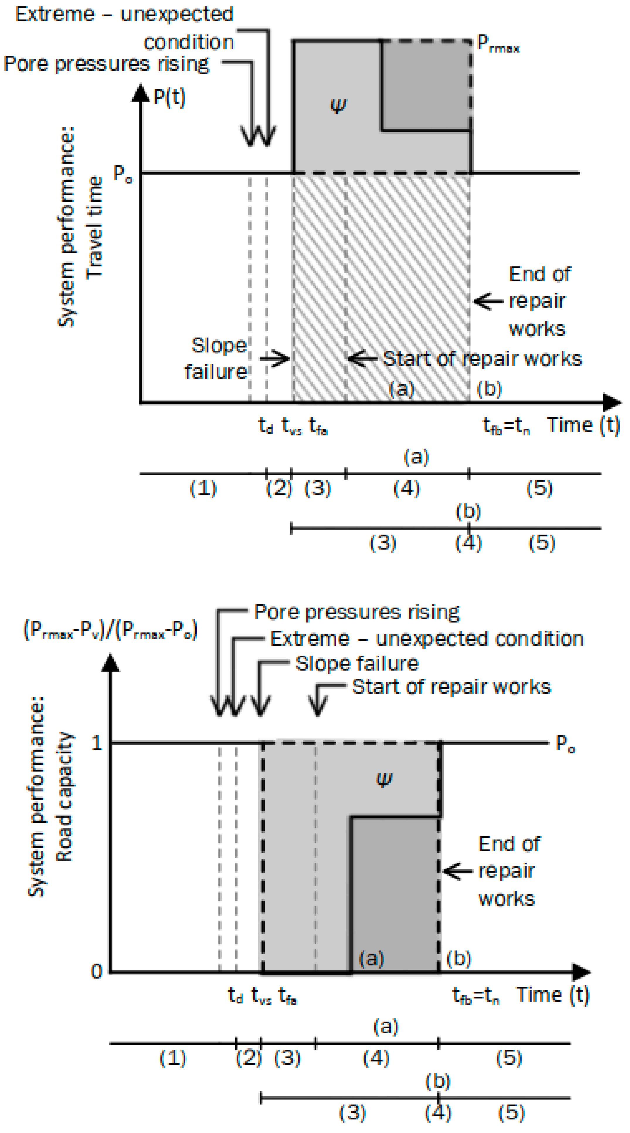
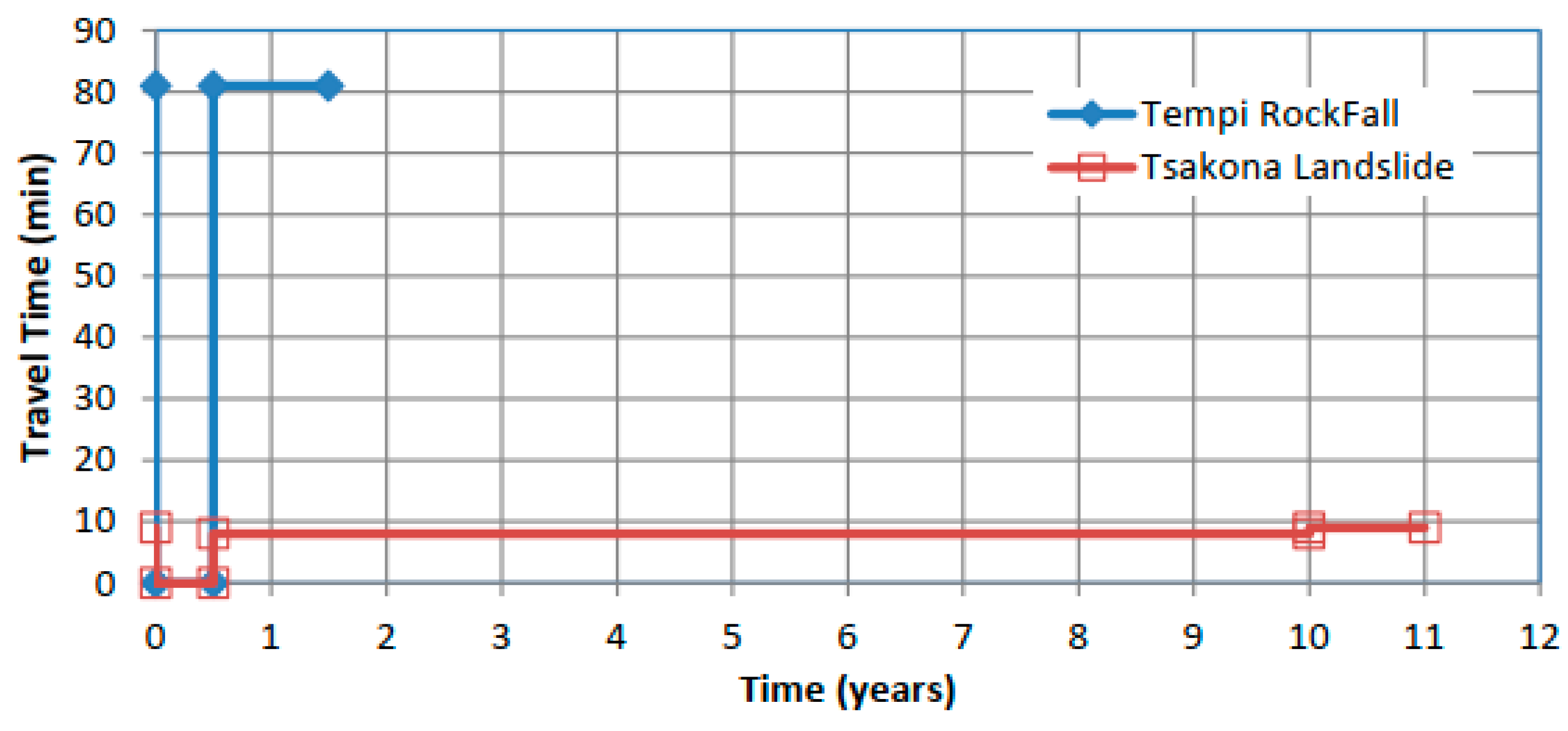
The current section presents two case studies, for which travel time is the performance function. Under an asset failure and complete disruption of a road network, traffic will temporarily follow a different route, performing a rerouting in which travel time takes its maximum value when Pv = Pmax = tmax. In the case studies investigated, a stepwise incremental response in one and two increments, respectively, is considered, with the typical response presented in Figure 5.
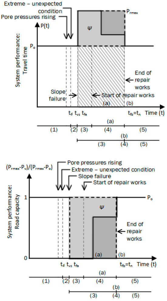
Figure 5.
Resilience response of slope road network asset that instantly fails.
For the one-increment response (case b), Equations (6b) and (7b) give Ψnorm = 0 under normal operation Pv(t) = Po (Figure 5) and
- (a)
- Ψnorm = Ψ/Ψmax = 1 for one-step recovery and Pv(t) = Prmax;
- (b)
- Ψnorm = Ψ/Ψmax > 1 for one-step recovery and Pv(t) > Prmax;
- (c)
- Ψnorm = Ψ/Ψmax < 1 for one-step recovery and Pv(t) < Prmax.
Nevertheless, there is an internal tn point at which traffic is partially re-established. If this point is near tvs, then Ψnorm moves to 0, and if it is near the final tn (at complete traffic restoration), then Ψnorm moves to 1. If the effect of Δtmax = tvs − tn on the Ψnorm needs to be investigated, then Equation (8c) is used instead of (8b), at the cost of normalizing with respect to from 0 to 1. By implementing Equations (7b) and (8b), the incorporation of multiple indices Ψnormi and an overall index possibly being the Ψnorm = Ψnorm1 × Ψnorm2 × is allowed.
4.1. Case Study 1: Landslide
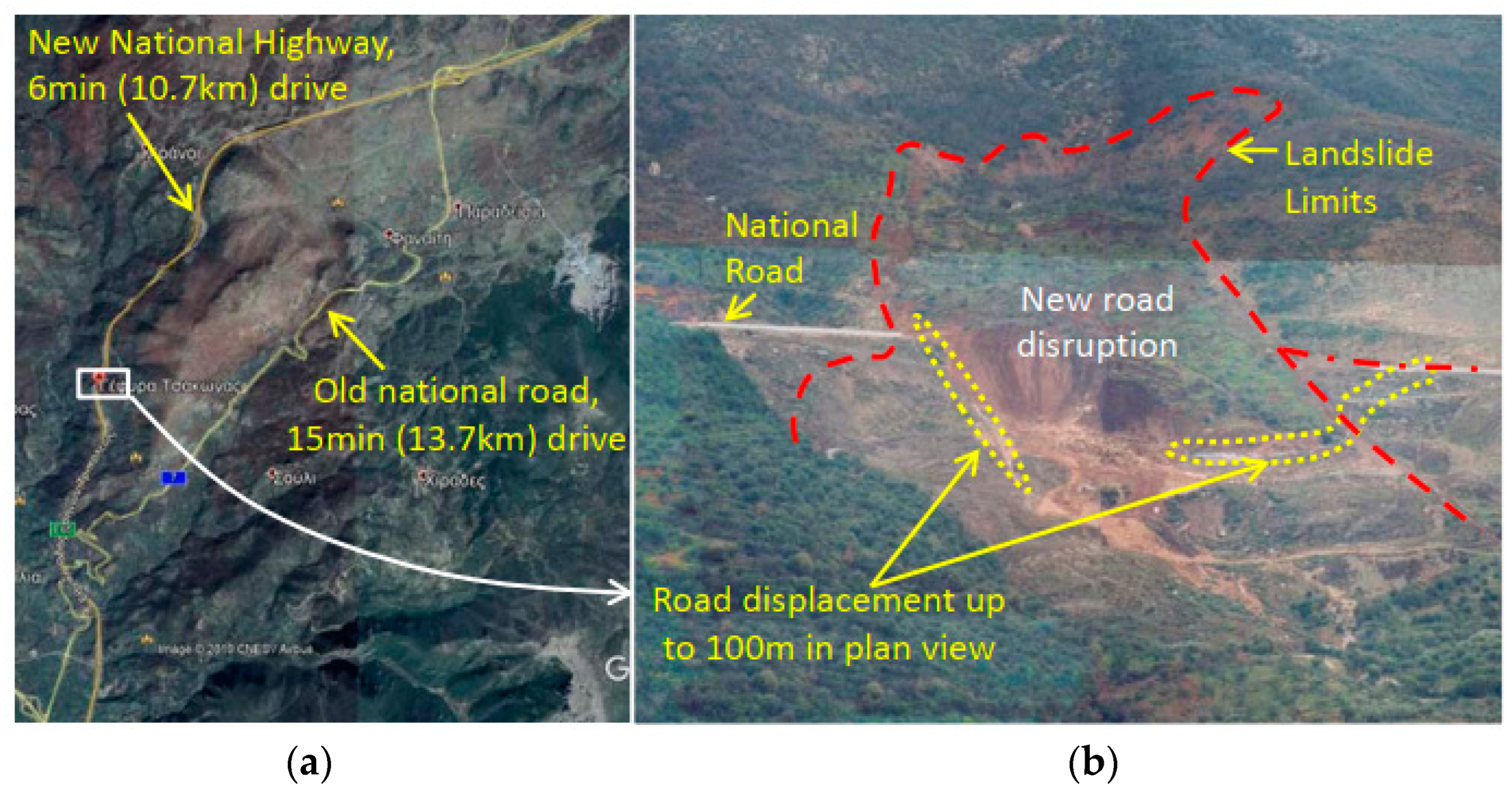
The first case study concerns a landslide in the Tsakona area, located in Greece. The landslide [18] occurred in 2003 at the 16.5 km point of the Tripolis—Kalamata national highway in the Peloponnese and disrupted a two-lane road (Figure 6) after 1 year of operation and 3 months of extreme rainfall. The result was the dysfunctionality of the 10.7 km long Paradeisia–Tsakona road network and the extensive remedial and improvement works along this route for 10 years.
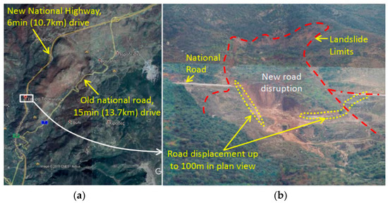
Figure 6.
The Tsakona landslide: (a) the network scale and (b) asset scale.
After the disruption and for approximately 6 months, the traffic was rerouted via another national road, which is considered an “old national road” (Figure 6). This road is a two-lane road, 13.7 km long, a 15 min drive, and less safe. A temporary 500 m long short diversion was opened next to the old route, with two lanes and a 7 min total drive time for the 10.7 km route, to partially restore capacity. Such diversion requires road traffic management over a total length of about 2 kms, reducing vehicle velocity from 110 k/h down to 50 km/h at maximum. The poorer traffic performance of the diversion compared to the rest of the highway is also accompanied by a safety-level operation that does not meet the required standards.
This failure resulted in the dysfunctionality of the 10.7 km long Paradeisia–Tsakona road network and in extensive remedial and improvement works along this route for 10 years. Ten years after the disruption, the 10.7 km route was restored, a bridge was built, and the route was upgraded to a four-lane road and 6 min drive but now safer.
The landslide in the Tsakona area is considered a failure of a high damage degree with low consequences in terms of human life. The reason is that the final big activation occurred within one month, thus allowing for the timely blocking of the road and the rerouting activation. Measurements of surface displacements, pore pressures, and rainfall intensity represent means of precautionary monitoring actions to successfully manage consequences. Geotechnical slope engineering analyses for adverse scenarios of various probabilities are required to determine the slope asset vulnerability to the hazard.
4.2. Case Study 2: Rockfall
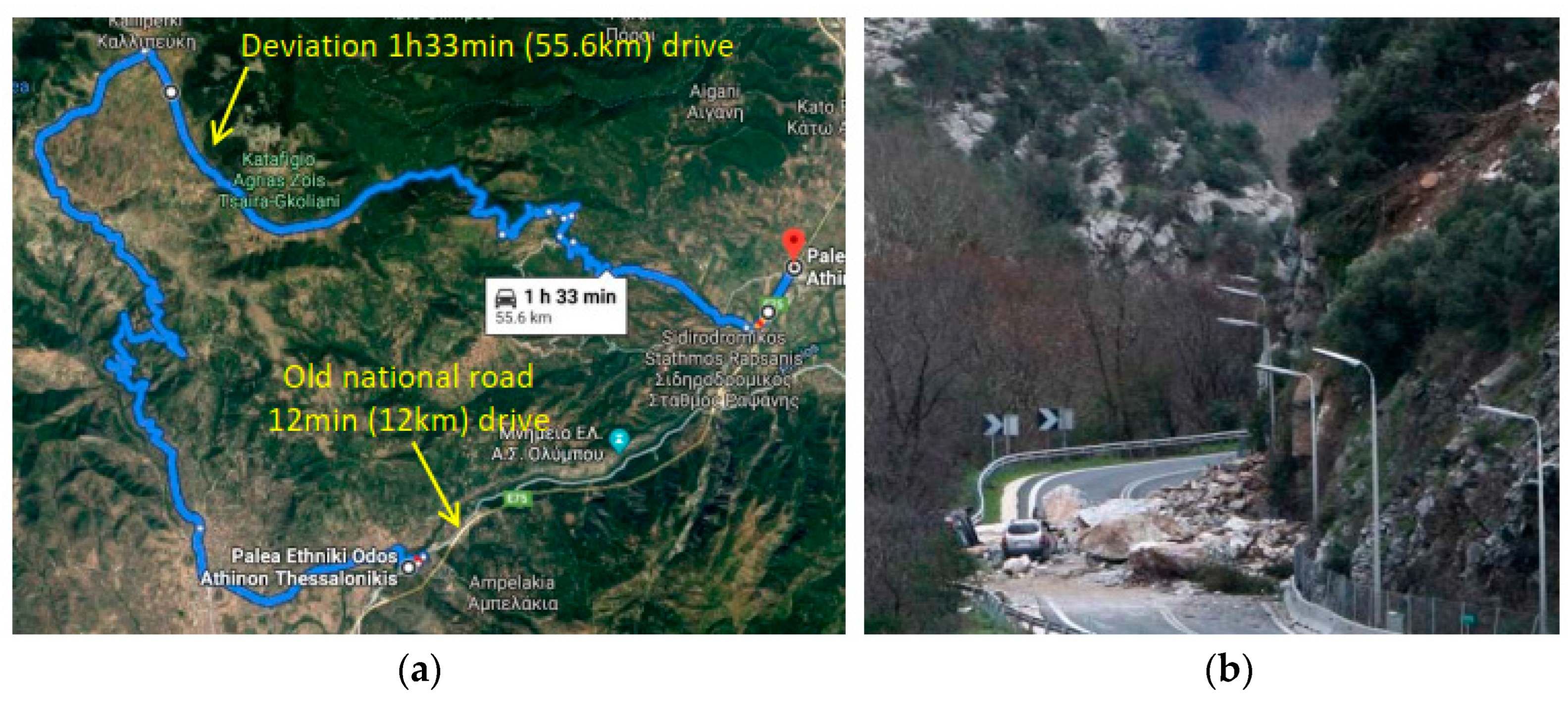
The second case study concerns a rockfall in the area of Tempi (Greece) [30]. The rockfall occurred in 2009 on the two-lane “old national road” located near the 380 km of the Athens-Thessaloniki national highway road after an extreme rainfall. This failure resulted in the disruption of the “old national road” (Figure 7, vulnerability) and one casualty (consequence). The “old national road” is 12 km long with a 12 min drive, while the alternative route that was decided on was 55.6 km long with a 1 h 33 min drive.
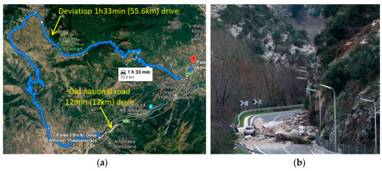
Figure 7.
The Tempi rockfall: (a) the network scale and (b) asset scale.
Six months after this failure, the road was considered safe to operate again. Today, a tunnel is in operation, with four lanes, 10 km long and a 5 min drive. This is considered as a significant upgrade in both safety and travel time.
The rockfall in the Tempi area is considered a failure of a high damage degree and with high consequences in terms of human life due to the very abrupt activation, which did not allow for precautionary actions. In terms of risk and resilience, it has a significant influence, which should eventually lead to measures to eliminate the consequences, even for highly vulnerable assets. Typical measures include rock barriers to reduce the energy of falling rocks. Measurements of surface displacements and rainfall intensity may also represent means of precautionary action to manage consequences. Geotechnical rock slope engineering analyses for adverse scenarios of various probabilities are required to determine the cliff asset vulnerability to the hazard.
4.3. Resilience Response
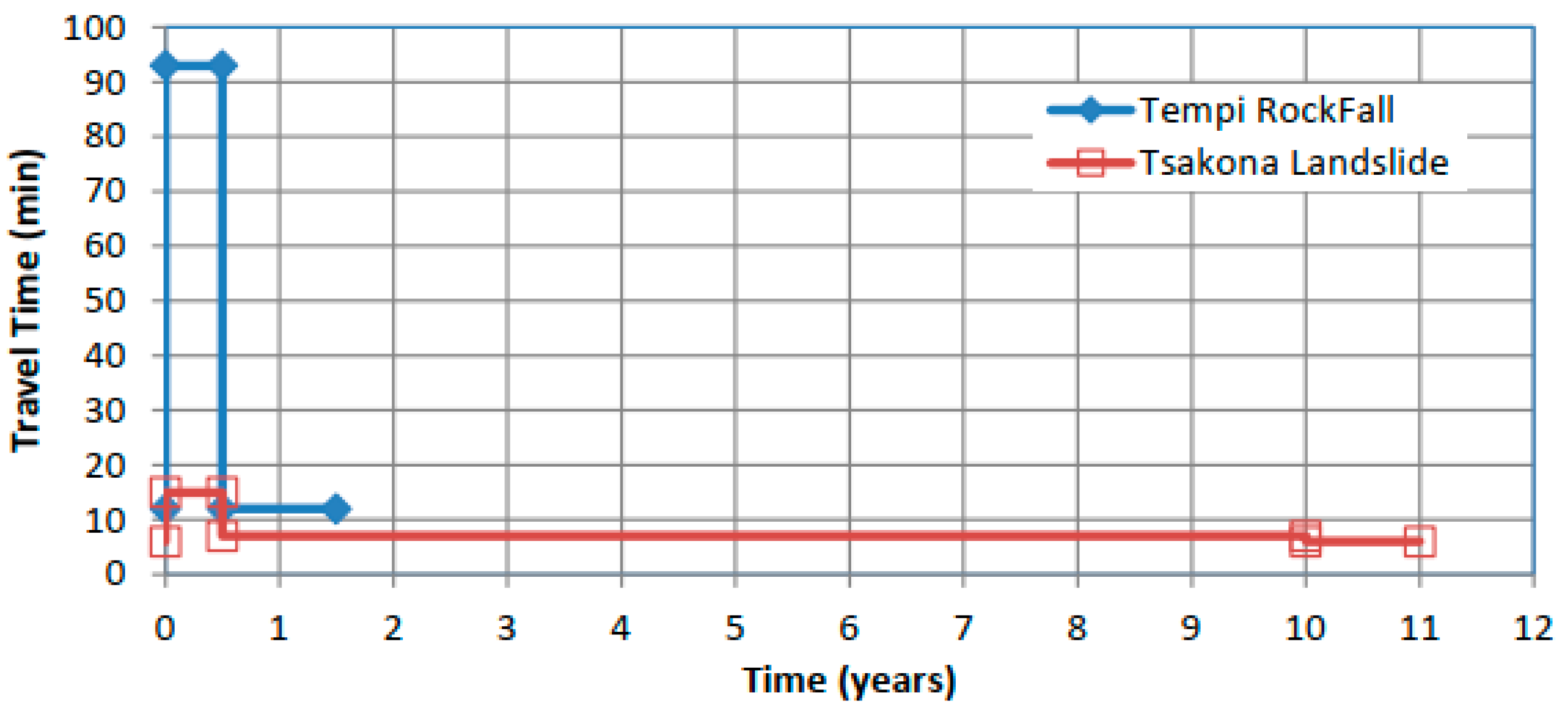
The case studies presented are characteristic. The network operates at different scales (i.e., in terms of distance and time as well as different recovery times) when one or more critical links fail (i.e., assets’ failure). The vulnerability of the network to hazards is high, depending on the criticality of the link. If more than one critical link fails, the recovery stage requires more effort as the cost and time increase. The resilience response curves are presented in Figure 8 and Figure 9.
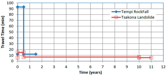
Figure 8.
Response: Travel time.
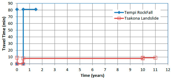
Figure 9.
Response: Resilience.
Equations (7b) and (8b) are applied, and the next two cases are presented:
- The landslide in the Tsakona area:It required 10 years to be totally restored and resulted in a low value of Ψnorm = 0.156 as partial traffic restoration was achieved in 05 years. This low value of Ψnorm is due to the two increments’ recovery and fast partial traffic restoration. If the traffic restoration was delayed, this would result in a higher value of Ψnorm.
- The rockfall in the Tempi area:It required 0.5 years to be totally restored, and the value of Ψnorm is equal to 1. This is due to the low adaptability of the system to the shock, and as a result, it is less resilient.
Nevertheless, the rockfall in the Tempi area took significantly less time to reach complete restoration. Considering the time restoration as well as the (Pmax − Pv)/(Pmax − Po) (i.e., not normalizing with Δtmax), the following is calculated (without the reference value of Ψnorm = 1.0):
- For the landslide in the Tsakona area: Ψnorm = 1.55 years.
- For the rockfall in the Tempi area: Ψnorm = 0.5 years.
5. Conclusions
The current paper presents resilience quantification methodologies for critical transport infrastructures. The analysis is approached under the prism of the societal, ecological, and technological (SET) framework. Each SET component has an influence on the smooth operation of the critical transport infrastructure. During their operation, resilience management tools can be used to improve the design of engineered systems, revise them, and assess the overall system response, even for unexpected and highly uncertain events. As transportation infrastructures operate within a dynamic SET environment, this analysis approach indicates that vulnerable assets may control the strength and resilience of the system. Moreover, a risk analysis alone is not sufficient for recent management tools because it does not account for the complete response after the disruption event.
The current work focuses on the influence of geotechnical assets’ failure on road and highway network performance. Interaction and interrelationships between different disciplines (meteorology, hydrology, geology, seismology, surface flow, subsurface flow, seismology, earthquake engineering) are required. The applied technique moves in this framework: the concept is generic and can be applied to any asset–network interaction of such a network but it also emphasizes and underlines the need for proposing a methodology that can be adapted to different sectors and disciplines. By providing a systematic way to analyze the interconnectedness and interdependencies among the critical infrastructure, a better understanding of the impacts of cascading ripple effects could be offered, thus mitigating risks in interconnected environments.
Quantifying resilience can be achieved through the use of indicators and resilience metrics. In this approach, two case studies of unexpected events in different areas located in Greece were presented, and simplified performance indicators were applied to quantify the instantaneous and the overall resilience. The results indicated that the appropriate selection of resilience metrics and normalized performance indicators can quantify the influence of the recovery stage, highlighting the added value of the applied methodology.
Resilience has been acknowledged as an essential requirement for transport networks [31]. Linking resilience to the performance of road networks and transport systems can describe the ability of infrastructure systems to withstand uncertain or unexpected events. By strategically addressing impacts on road networks rather than focusing simply on linear corridors, the overall adaptability and efficiency of the entire transportation system could be enhanced. This approach identifies the complex relationships between transport supply and demand, emphasizing the need for holistic resilience measures and metrics that consider the structure and dynamics of transport networks. Another limitation of the current work is that although the methodological approach presented was applied to real case studies, extracting concrete findings, there is room for highlighting areas for improvement with its validation. By systematically evaluating and verifying the accuracy of the applied methodology through empirical evidence, contributions and suggested ways for future research could be addressed.
In this context, further research for the development and application of dynamic operational resilience management tools for critical transport infrastructures would be an important achievement. Decision makers could facilitate this by investing in the creation of advanced tools to respond to the dynamic nature of operational challenges, effectively respond to unforeseen disruptions, and ensure the sustainability of critical transport infrastructure. Yet, enabling the management and orchestration of further research frameworks must be based on the establishment of cooperation schemes between all relevant parties, setting and ensuring public–private partnerships for passengers, and freight transport data collection and sharing [32].
Author Contributions
Conceptualization, G.B. and C.S.; validation, G.B., C.S., T.P.M. and E.I.V.; investigation, G.B.; resources, C.S.; original draft preparation, G.B. and C.S.; writing—review and editing, T.P.M. and E.I.V.; visualization, G.B., C.S., T.P.M. and E.I.V.; supervision, G.B., C.S., T.P.M. and E.I.V. All authors have read and agreed to the published version of the manuscript.
Funding
This research received no external funding.
Institutional Review Board Statement
Not applicable.
Informed Consent Statement
Not applicable.
Data Availability Statement
The data are available upon reasonable requests from the corresponding author.
Conflicts of Interest
The authors declare no conflicts of interest.
References
- European Union. DIRECTIVE (EU) 2022/2557 of the European Parliament and of the Council of 14 December 2022 on the Resilience of Critical Entities and Repealing Council Directive 2008/114/EC. Off. J. Eur. Union 2022, 333, 164–198. [Google Scholar]
- European Commission. Regulation (EU) No 1315/2013 of The European Parliament and of the Council of 11 December 2013 on Union Guidelines for the Development of the Trans-European Transport Network and Repealing Decision No 661/2010/EU. Available online: https://eur-lex.europa.eu/eli/reg/2013/1315/oj (accessed on 18 February 2024).
- European Union. COUNCIL DIRECTIVE 2008/114/EC on the identification and designation of European critical infrastructures and the assessment of the need to improve their protection. Off. J. Eur. Union 2008, 345, 75–82. [Google Scholar]
- CISA. Critical Infrastructure Sectors. Available online: https://www.cisa.gov/topics/critical-infrastructure-security-and-resilience/critical-infrastructure-sectors (accessed on 18 February 2024).
- CISC. Security of Critical Infrastructure Act 2018 (SOCI). 2018. Available online: https://www.cisc.gov.au/legislation-regulation-and-compliance/soci-act-2018 (accessed on 18 February 2024).
- CEN/TC Business Plan 250 Structural Eurocodes; European Commission: Brussels, Belgium, 2014.
- Markolf, S.A.; Chester, M.V.; Eisenberg, D.A.; Iwaniec, D.M.; Davidson, C.I.; Zimmerman, R.; Miller, T.R.; Ruddell, B.L.; Chang, H. Interdependent Infrastructure as Linked Social, Ecological, and Technological Systems (SETSs) to Address Lock-in and Enhance Resilience. Earth’s Future 2018, 6, 1638–1659. [Google Scholar] [CrossRef]
- UNISDR (United Nations International Strategy for Disaster Reduction). UNISDR Terminology on Disaster Risk Reduction; United Nations: Geneva, Switzerland, 2009. [Google Scholar]
- USAID. Introduction to Disaster Risk Reduction; USAID: Washington, DC, USA, 2011. [Google Scholar]
- Liu, K.; Wang, Q.; Wang, M.; Koks, E. Global Transportation Infrastructure Exposure to the Change of Precipitation in a Warmer World. Nat. Commun. 2023, 14, 2541. [Google Scholar] [CrossRef] [PubMed]
- World Meteorological Organization. Rate and Impact of Climate Change Surges Dramatically in 2011–2020. December 2023. Available online: https://wmo.int/news/media-centre/rate-and-impact-of-climate-change-surges-dramatically-2011-2020 (accessed on 18 February 2024).
- Cimellaro, G.P.; Reinhorn, A.M.; Bruneau, M. Framework for Analytical Quantification of Disaster Resilience. Eng. Struct. 2010, 32, 3639–3649. [Google Scholar] [CrossRef]
- Kong, J.; Simonovic, S.P.; Zhang, C. Resilience Assessment of Interdependent Infrastructure Systems: A Case Study Based on Different Response Strategies. Sustainability 2019, 11, 6552. [Google Scholar] [CrossRef]
- Sajjad, M.; Chan, J. Risk Assessment for the Sustainability of Coastal Communities: A Preliminary Study. Sci. Total Environ. 2019, 671, 339–350. [Google Scholar] [CrossRef] [PubMed]
- Saunders, W.S.A.; Becker, J.S. A Discussion of Resilience and Sustainability: Land Use Planning Recovery from The Canterbury Earthquake Sequence, New Zealand. Int. J. Disaster Risk Reduct. 2015, 14 Pt 1, 73–81. [Google Scholar] [CrossRef]
- European Commission. Overview of Natural and Man-Made Disaster Risks in the EU Accompanying the Document Communication from the Commission to the European Parliament, the Council, the European Economic and Social Committee and the Committee of the Regions the Post 2015 Hyogo Framework for Action: Managing Risks to Achieve Resilience; European Commission: Brussels, Belgium, 2014. [Google Scholar]
- Belokas, G.; Saroglou, C.; Moschovou, T.; Vlahogianni, E. Transport Infrastructure Resilience: From Geotechnical Asset to Transport Network. In Proceedings of the 3rd International Conference on Natural Hazards & Infrastructure, Athens, Greece, 5–7 July 2022. [Google Scholar]
- Helm, P.R.; Svalova, A.; Morsy, A.M.; Rouainia, M.; Smith, A.; El-Hamalawi, A.; Wilkinson, D.J.; Postill, H.; Glendinning, S. Emulating long-term weather-driven transportation earthworks deterioration models to support asset management. Transp. Geotech. 2024, 44, 101155. [Google Scholar] [CrossRef]
- Belokas, G.; Dounias, G. The Tsakona Landslide in Peloponnese—Greece. Riv. Ital. Geotech. 2016, 50, 34–50. [Google Scholar]
- Mateos, R.M.; Vinielles, J.L.; Poyiadji, E.; Tsagkas, D.; Sheehy, M.; Hadjicharalambous, K.; Liscák, P.; Podolski, L.; Laskowicz, I.; Iadanza, C.; et al. Integration of Landslide Hazard into Urban Planning Across Europe. Landsc. Urban Plan. 2020, 196, 103740. [Google Scholar] [CrossRef]
- Baioni, D. Human Activity and Damaging Landslides and Floods on Madeira Island. Nat. Hazards Earth Syst. Sci. 2011, 11, 3035–3046. [Google Scholar] [CrossRef]
- Hearn, G.; Larkin, H.; Papageorgiou, A.; Zoi, G.E. Acceleration of the Pissouri landslide, Cyprus. Q. J. Eng. Geol. Hydrogeol. 2020, 53, 530–541. [Google Scholar] [CrossRef]
- Moschovou, T.; Giannopoulos, A. Assessing the Impact on freight transport and treating uncertainty in freight transport modelling in the Covid pandemic: The case of Greece. Adv. Transp. Stud. Int. J. 2023, 60, 141–158. [Google Scholar]
- Tagarelli, V.; Cotecchia, F. Preliminary Field Data of Selected Deep-Rooted Vegetation Effects on The Slope-Vegetation-Atmosphere Interaction: Results from an In-Situ Test. Riv. Ital. Geotec. 2022, 62–83. [Google Scholar] [CrossRef]
- Yodo, N.; Wang, P. Engineering Resilience Quantification and System Design Implications: A Literature Survey. J. Mech. Des. 2016, 138, 111408. [Google Scholar] [CrossRef]
- Munoz, A.; Dunbar, M. On the Quantification of Operational Supply Chain Resilience. Int. J. Prod. Res. 2015, 53, 6736–6751. [Google Scholar] [CrossRef]
- Bruneau, M.; Chang, S.E.; Eguchi, R.T.; Lee, G.C.; O’Rourke, T.D.; Reinhorn, A.M.; Shinozuka, M.; Tierney, K.; Wallace, W.A.; von Winterfeldt, D. A Framework to Quantitatively Assess and Enhance the Seismic Resilience of Communities. Earthq. Spectra 2003, 19, 733–752. [Google Scholar] [CrossRef]
- Ouyang, M.; Dueñas-Osorio, L.; Min, X. A Three-Stage Resilience Analysis Framework for Urban Infrastructure Systems. Struct. Saf. 2012, 36, 23–31. [Google Scholar] [CrossRef]
- Ouyang, M.; Wang, Z. Resilience Assessment of Interdependent Infrastructure Systems: With a Focus on Joint Restoration Modeling and Analysis. Reliab. Eng. Syst. Saf. 2015, 141, 74–82. [Google Scholar] [CrossRef]
- Saroglou, C. GIS-Based Rockfall Susceptibility Zoning in Greece. Geosciences 2019, 9, 163. [Google Scholar] [CrossRef]
- Chalkiadakis, C.; Perdikouris, A.; Vlahogianni, E. Urban Road Network resilience metrics and their relationship: Some experimental findings. Case Stud. Transp. Policy 2022, 10, 2377–2392. [Google Scholar] [CrossRef]
- Moschovou, T.; Vlahogianni, E.I.; Rentziou, A. Challenges for Data Sharing in Freight Transport. Adv. Transp. Stud. Int. J. 2019, 48, 141–152. [Google Scholar]
Disclaimer/Publisher’s Note: The statements, opinions and data contained in all publications are solely those of the individual author(s) and contributor(s) and not of MDPI and/or the editor(s). MDPI and/or the editor(s) disclaim responsibility for any injury to people or property resulting from any ideas, methods, instructions or products referred to in the content. |
© 2024 by the authors. Licensee MDPI, Basel, Switzerland. This article is an open access article distributed under the terms and conditions of the Creative Commons Attribution (CC BY) license (https://creativecommons.org/licenses/by/4.0/).

