Article

NACA 2412 Drag Reduction Using V-Shaped Riblets

1
Department of Engineering, Staffordshire University, Stoke on Trent ST42DE, UK
2
Department of Power Engineering and Mechatronics, Tallinn University of Technology, Ehitajate tee 5, 19086 Tallinn, Estonia
*
Authors to whom correspondence should be addressed.
Eng 2024, 5(2), 944-957; https://doi.org/10.3390/eng5020051
Submission received: 10 March 2024 / Revised: 8 May 2024 / Accepted: 17 May 2024 / Published: 23 May 2024

Abstract

:
This research focuses on addressing a significant concern in the aviation industry, which is drag. The primary objective of this project is to achieve drag reduction through the implementation of riblets on a wing featuring the NACA 2412 aerofoil, operating at subsonic speeds. Riblets, with the flow direction on wing surfaces, have demonstrated the potential to effectively decrease drag in diverse applications. This investigation includes computational analysis within the ANSYS Workbench framework, employing a polyhedral mesh model. The scope of this research encompasses the analysis of both a conventional wing and a modified wing with riblets. A comparative analysis is conducted to assess variations in drag values between the two configurations. Parameters, including geometry, dimensions, and riblet placement at varying angles of attack, are explored to comprehend their impact on drag reduction. Notably, 15.6% and 23% reductions in drag were identified at a 16-degree angle of attack with midspan and three-riblet models, separately. The computational mesh and method were validated using appropriate techniques.

1. Introduction

The energy crisis in the current environment can be managed by developing renewable energy resources and reducing aircraft emissions [1]. Kuhn et al. mentioned in their work that the aviation industry has some limitations on using renewable energies, such as hydrogen fuel and solar energy, and hence, it is essential to protect the available fuels through their proper and planned usage [2]. In aircrafts, the fuel consumption can be reduced by implementing proper lift increment techniques by reducing the drag components and thereby increasing the lift-to-drag ratio, which is a measure of an aircraft’s aerodynamic efficiency. Reducing aircraft drag is a crucial area of research in aerospace engineering due to its direct impact on aircraft performance, efficiency, and sustainability. Since data show that one count of drag increase (ΔCd = 0.0001) is equal to two passenger weights in concord aircrafts [3], drag reduction methods are more relevant all the time. Among the various sources of drag on an aircraft, the wing has been a primary focus for developing drag reduction methods. Through extensive research, innovative techniques have been explored to reduce drag on aircraft wings, resulting in improved fuel efficiency, increased range, and reduced environmental impact.
There are many ways to control the drag, for example, increasing the Reynolds number can reduce the drag by minimizing the size of the boundary layer [4]. However, there is a possibility of instabilities in the flow due to the implementation of boundary-layer decrement. The other way of reducing the drag is by changing the design of the aircraft wing surfaces. The study performed by Zeno et al. illustrated that the design change performed with anti-fairing reduced the drag [5]. With the use of surface roughness elements, such as dimples, drag can be reduced by controlling the flow separation [6]. There was a significant decrease in skin friction drag when a NACA 2412 aerofoil with variable-aspect-ratio dimples was examined. The three-dimensional inwardly dimpled wing at various angles of attack demonstrated that the air in the dimple surface accelerates, changing the boundary layer from laminar to turbulent. This delay in flow separation lowers drag. Even though it affects lift and drag, there are certain problems with the viability of creating dimples in an aircraft wing, and it also depends on where and how big the dimples are. It is not possible to apply this strategy to every aerofoil profile [7].
The main drag component, which contributes half of the total drag, is skin friction drag. It can be limited by employing laminar flow control that can be performed by using the hybrid laminar flow concept, which was conducted by applying suction in the leading-edge region to control the development of cross flow, and it helped to improve the aircraft performance. While it failed, the maintenance of this setup became a challenge since it was affected by insect debris and roughness, which affects its performance [8]. Surface modifiers, such as vortex generators, were employed to mitigate drag by inducing turbulence without enhancing the coefficient of lift, which helped in postponing flow separation. However, the placement of these vortex generators is crucial, and they might not function effectively at lower angles of attack. Moreover, there is a potential for induced drag caused by trailing-edge vortices stemming from the use of vortex generators [9].
Another passive-separation-control technique using bumps employed in an SD7003 rectangular wing with a low Reynolds number provided a good improvement in the lift-to-drag ratio. The bumps were positioned in close proximity to the leading edge of the wing to enhance aerodynamic performance by managing the bubbles resulting from laminar separation to avoid flow separation. Although it was possible to minimise the pressure drag forces, the degree of that reduction was heavily influenced by other factors, including the angle of attack and the number, placement, and size of the bumps [10].
The experiment conducted in a wind tunnel on a blunt wing with surface roughness gave a good picture of how flow behaviour influences drag. However, the amount of drag decrement and flow behaviour have a strong correlation with the leading-edge contour and roughness height [11]. Large tripping in turbulent flow was seen in another study on flow behaviour using a spanwise row of cylindrical roughness components in a laminar, compressible three-dimensional boundary layer on a wing profile. It changed the location of the transition, causing an advance transition. However, it deliberately increased the flow’s instabilities and turbulent effect [12]. The study was carried out to examine how an aerofoil’s flow separates when its upper surface is partially uneven. Tests were conducted in a subsonic wind tunnel at a 14-degree angle of attack. This demonstrated how the bumpy surface can be used to postpone the aerofoil’s flow separation while increasing lift force. This experimental study has shown that modifications involving frequent disturbances, or “bumps,” can postpone the flow separation on the aerofoil’s surface. However, the actual implementation in aeroplanes is a little more difficult [13]. Based on the review, it can be concluded that there is a significant lack of efficient drag reduction methods.
Utilizing riblets to close this gap is promising and has drawn a lot of interest. Due to their capacity in flow control dynamics and minimizing resistance, riblets have become recognized as a possible tool for lowering drag. This idea is extracted from sharkskin, which is made of tiny keels, as shown in Figure 1. Riblets come in many shapes and sizes based on the shark species. For example, Isurus oxyrinchus has a height of 0.012 mm and a spacing of 0.041 mm, and Carcharhinus limbatus has a height of 0.029 mm and a spacing of 0.065 mm [14]. The flow separation on a staggered array of scales can lead to the scales becoming disrupted, causing a disturbance in the flow separation process and resulting in a delay in transition from laminar to turbulent. This helps to reduce the skin friction drag that emerges from the no-slip boundary effect. When the shark swims at speeds exceeding 10 m/s, the riblet induces turbulent flow over its skin due to the high Reynolds number. Even this turbulent boundary layer is less resistant to separation, leading to increased skin friction drag compared to a purely laminar flow scenario. The riblet mechanism can reduce 8 to 10% of the total skin friction drag [14,15,16,17,18,19].
The effectiveness of drag reduction using riblet surfaces is impacted by a range of elements, encompassing factors like riblet geometry, Reynolds number, surface roughness, riblet alignment, interaction with the boundary layer, and many more. The main concept behind the implementation of riblets is making the surface rough, which reduces the amount of drag in turbulent regions, especially in stalling [21]. Another study noted that the riblets lessen momentum transfer by reducing the vortices and cross flow velocity in the turbulent region. This influenced the turbulence to become less intense and postponed the transition to turbulence [22,23]. Hence, in this research, an attempt was made to reduce the drag on a subsonic NACA 2412 wing using riblets. This aerofoil was selected because it is an asymmetrical aerofoil that offers lift, even at zero angle of attack, and still requires improvement.

2. Computational Design

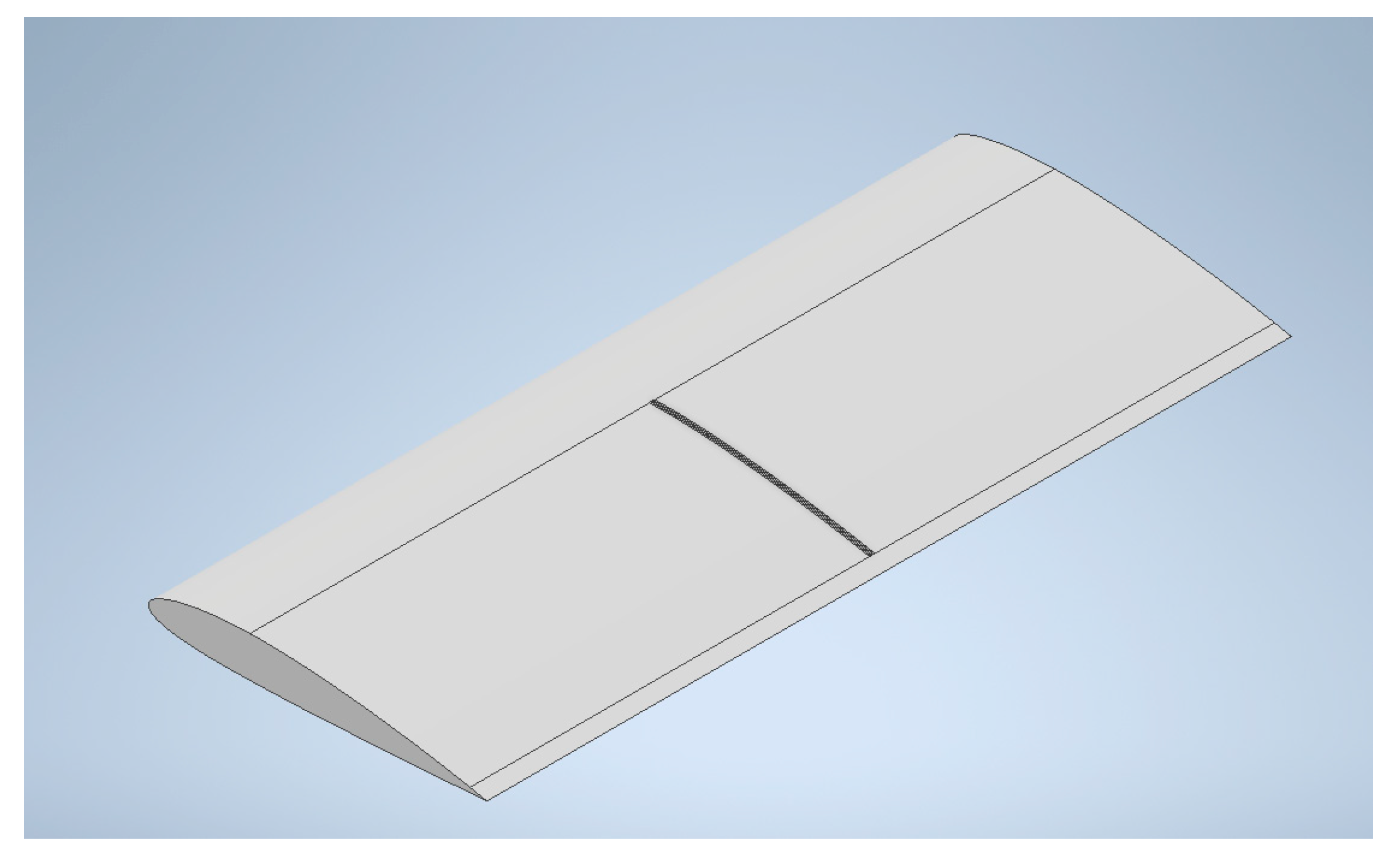
The NACA 2412 aerofoil with a chord length of 127 mm [24,25] was used in both the wing root and the wing tip to develop a rectangular-shaped wing of wingspan 381 mm (762/2 = 381 mm), as it is one of the wing forms that produces more lift and less drag in the subsonic flow regime, and a constant taper ratio of 1:1 produces more lift than other wings [26]. The wing model was designed using aerofoil coordinates with the help of ANSYS Design Modeler 2022 R2 and Autodesk Inventor 2023. A riblet’s dimension selection holds significant importance, as heightened surface roughness corresponds to elevated skin friction. This outcome contributed to an overall rise in drag [27]. The largest drag reduction occurred when the h/s ratio (h is the riblet’s height, and s is the separation) for sawtooth riblets is 0.5, which was evidenced by Heidarian and Ghassemi, in which they looked at the spacing, height, and microchannels of the riblets in various flow velocities [28]. The scalloped riblets with a h/s of 0.7 showed a maximum drag reduction of 5.1%, and the sawtooth riblets with a h/s of 0.5 showed a maximum drag reduction of 11% [28]. Since this study shows the h/s = 0.5 ratio showed a good drag reduction, the initial design was performed with h/s = 0.5 (h = 0.002C = 0.254 mm, S = 0.00397C = 0.50419 mm). However, while performing the analysis, there was no proper improvement in drag reduction. So, a riblet with a h/s of 0.8 (h = 0.002c = 0.254 mm and s = 0.0025c = 0.3175 mm) was developed and used in this research. Yufei et al. noted in their research that the drag was reduced more effectively when the riblets were inclined at 15 degrees than when they were inclined at 30. They also observed that the drag increased when the angle increased from 20 to 30 degrees. Hence, in this project, the position and geometry of the riblet were focused on to improve the drag reduction. The riblet design was placed between 0.3c and 0.95c based on the previous study on the best location for drag reduction [29] and aligned parallel to the flow direction [30]. Figure 2 shows the wing surface with four riblets positioned at the centre of the wingspan, each adhering to the dimensions previously described. The wing surface with riblets placed at three distinct positions, as depicted in Figure 3, was used to observe the variations in drag and lift values. Figure 4 provides a close view of the riblets, which looks in the form of isosceles triangles arranged spanwise on the wing surface.

3. Computational Mesh

The impact of a computational domain was studied by comparing C, O, and rectangular types, and the C-type computational domain was chosen, as it suited the model’s blunt leading edge and sharp trailing edge [31]. This C domain was designed around the model based on 20 times the chord length of the wing [24] at the front and back, as shown in Figure 5, to capture the changes in the fluid flow. A rectangular-shaped body of influence (BOI) was introduced near the wing, approximately 100 mm away, with the intention of enhancing flow visualization by improving the accuracy of mesh within a particular region in the geometry. This involves refining the mesh in specific, significant areas, particularly those that exhibit intricate flow patterns or require heightened precision. This helps obtain a more precise representation of essential flow characteristics and gradients [32].
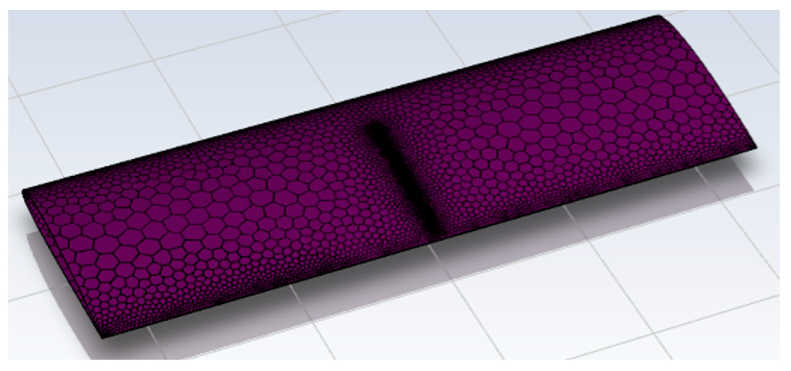
After several attempts, it was found that the tetrahedral mesh could not provide the necessary quality of orthogonality and skewness, particularly in the trailing edge. When the mesh type changed to hexahedron, it was challenging to generate structure mesh in the corners, and the computational time of hexahedron mesh was high. Due to these issues encountered, the polyhedral mesh was chosen for the 3D analysis, as it can provide a high level of quality, can increase the numerical stability of the solution when compared to tetrahedral, and has fewer cells than other mesh types and hence displays fewer elements overall [33]. The Y+ distance (between the boundary and the first grid’s centre) is an additional parameter that must be taken into consideration when meshing because this helps find whether a mesh is fine or coarse. The wall Y+ was maintained between 30 and 300 based on the previous research [34] to suit the K-Ꜫ turbulence model with standard wall function [35] used to mesh the model. The mesh obtained had a skewness (deviation of the cell from its optimal cell size) in the range of 0.25 to 0.85 [36] and an orthogonal quality of above 0.1 [37]. These values represented that a good mesh was made of reasonable quality. Figure 6 shows the mesh on the wing surface with riblets. In polyhedral mesh, the boundary conditions were required to be set before converting the surface mesh to solid mesh.
Setting the boundary conditions was necessary in polyhedral mesh before turning the surface mesh into solid mesh. Inlets, outlets, and symmetry boundaries were categorised using the ANSYS Update Boundaries option. Riblet surfaces, such as top, right, left, and aerofoil surfaces (leading edge and mid-surface without riblet), were considered walls. This enables the air to flow over the wall surface. If the rate of flow is known, the inlet can be called a velocity inlet and the pressure, which is unknown, can be called a pressure outlet [38]. Thus, for this investigation, the pressure outlets and velocity inlet were used.

4. Computational Analysis

Computational fluid dynamics (CFD) offers a numerical approximation to the equations that dictate the movement of fluids. The group of partial differential equations, such as Navier–Stokes equations, Euler equations, and Reynolds-averaged Navier–Stokes (RANS) equations, that characterize fluid flow are formulated [39]. The simulation of the riblet wing is performed using a pressure-based solver because it is more effective in incompressible flows. The SIMPLE solution method was applied, as it effectively attains a steady-state solution when coupled with an implicit time treatment for flow variables. This method enhances the stability and convergence of the iterative process [40].
In this research, the K-Ꜫ turbulence model is used because it has been shown to be suitable for representing pressure distribution and illustrating the wake area [41], is easy to apply, and is valid for all types of flows [42]. The standard K-Ꜫ model is a two-equation model (K = turbulent kinetic energy, Ꜫ = rate of dissipation of turbulent kinetic energy). When examining regular aerodynamic behaviours, steady flow is employed. In such instances, the right-hand components of continuity and diffusivity equations become zero, as there is no change with respect to time. This means that the flow parameters, such as pressure and velocity, remain constant and do not vary over time [43]. By integrating and assessing the boundary condition constants, one can formulate steady-state flow equations. The steady-state flow equations are built upon the principles of uniform thickness and incompressible flow [41]. The standard wall approach helps capture the effects of viscosity and turbulence near the wall, which are crucial factors in aerodynamic analysis [44].
The transport equation for turbulent kinetic energy is shown below:
ρ k t + ρ k U i x i = x j [ ( μ + μ t σ k ) k x j ] + P k + P b ρ ϵ + S k
where Pk = production of turbulent kinetic energy (TKE) due to mean velocity shear, Pb = production of TKE due to buoyancy, Sk = user-defined source, and σk = turbulent Prandtl number for k.
The transport equation for the turbulent dissipation rate is shown below:
ρ ϵ t + ρ ϵ U i x i   = x j [ ( μ + μ t σ ϵ ) ϵ x j ] + C 1 ϵ k ( P k + C 3 P b ) C 2 ρ ϵ 2 k + S ϵ
where C1, C2, and C3 are coefficients specific to K-ϵ turbulence models that exhibit variation, Sϵ = user-defined source, and σϵ = turbulent Prandtl number for ϵ [45].
Establishing a boundary condition during a CFD analysis influences the outcome since the choice of boundary condition relies on the given parameters. When the flow rate is a known factor, the inlet can be designated as a velocity inlet, while the pressure, which is to be determined, is assigned as a pressure outlet [38]. The free stream velocity of this study is decided as 20.73 m/s, with a higher Reynolds number of 1.8 × 10⁵, as the flow is incompressible. The Mach number of this flow is calculated as M = velocity/speed of sound = 20.73/340 = 0.06 [46]. The flow is incompressible since the Mach number is less than 0.3. Additionally, it was identified that the flow is turbulent based on the calculation mentioned below [47]:
Reynolds number , R = Vc / v = ( 20.73 × 0.127 ) / ( 1.46073 × 10 5 ) = 1.8 × 10 5 .
where v is the flow speed = 20.73 m/s, c is chord length = 0.127 m, ν is kinematic viscosity, μ = viscosity = 1.7894 × 10⁻⁵ kg/ms, ρ = density, 1.225 kg/m3, and ν = μ/ρ = (1.7894 × 10⁻⁵)/(1.225) = 1.46073 × 10⁻⁵ m2/s.
The designed NACA 2412 wing and the wing with riblets placed at the midspan have a specific h/s ratio of 0.8 (as discussed in the computational design section) and were analysed using the K-Ꜫ viscous model, computationally, in airflow at different angles of attack, such as 0°, 4°, 8°, 12°, 16°, 20°, and 24°.

5. Computational Result Analysis

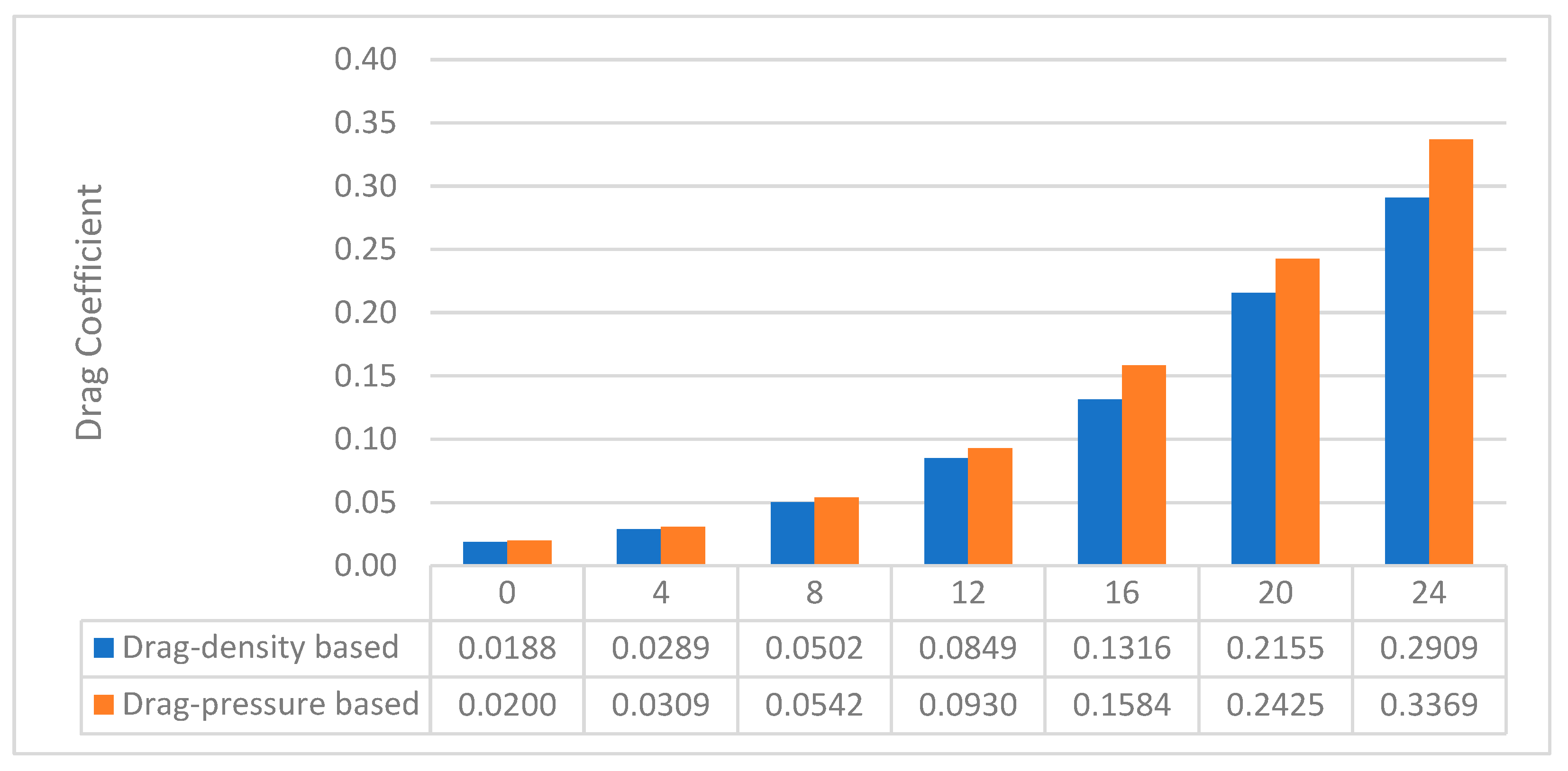
The riblet wing model was analysed using both density- and pressure-based solvers, although the latter is more suitable for incompressible flows. The outcomes of these analyses were very close, as shown in Figure 7. Figure 8 shows a significant amount of drag reduction attained in the riblet wing between the 10° and 20° angles of attack. In order to analyse the drag value, the default output parameter, called the drag coefficient, was monitored and studied in the case of fluid analysis. The drag coefficient is derived from the drag equation [48], which is
D = 1 2 ρ v 2 C d S ,
where
D—drag force acting on the object;
ρ—fluid density (here, this is considered to be the air density);
v—the velocity between the object and fluid;
Cd—drag Coefficient
S—surface area of the object.
Figure 7. Drag coefficient—pressure- and density-based solvers—riblet wing.
Eng 05 00051 g007
Figure 8. Drag coefficient—normal vs. riblet wings.
Eng 05 00051 g008
Despite being a dimensionless parameter, the drag coefficient scales the drag force according to the object’s surface area, flow velocity, and flow density. The shape of the object, the roughness of the surface, and the fluid characteristics are other variables that a drag coefficient may impact.
C d = 2 D ρ v 2 S
The streamlined shape of the wing was the main focus of the design since a low drag coefficient reduces air resistance between the item and its surroundings [49]. While using a riblet wing, a larger amount of 15.6% drag reduction was observed in the riblet wing at the 16° angle of attack.
Because of the relatively low velocity between the riblets and the high velocity experienced at the riblet tip due to its specific localised location, the riblet behaviour at the 0° angle of attack demonstrates a 5.7% reduction in total drag. Figure 9 clearly shows that the level of velocities has been increased on the top surface, especially the areas where the riblet was implemented. This increment in the velocity on the top surface of a riblet-implemented wing favoured the drag reduction, as expected. This reduction in drag can be attributed not only to a decrease in turbulent friction but also to the mitigation of the separation area and otherwise smooth trailing section of the object [50].
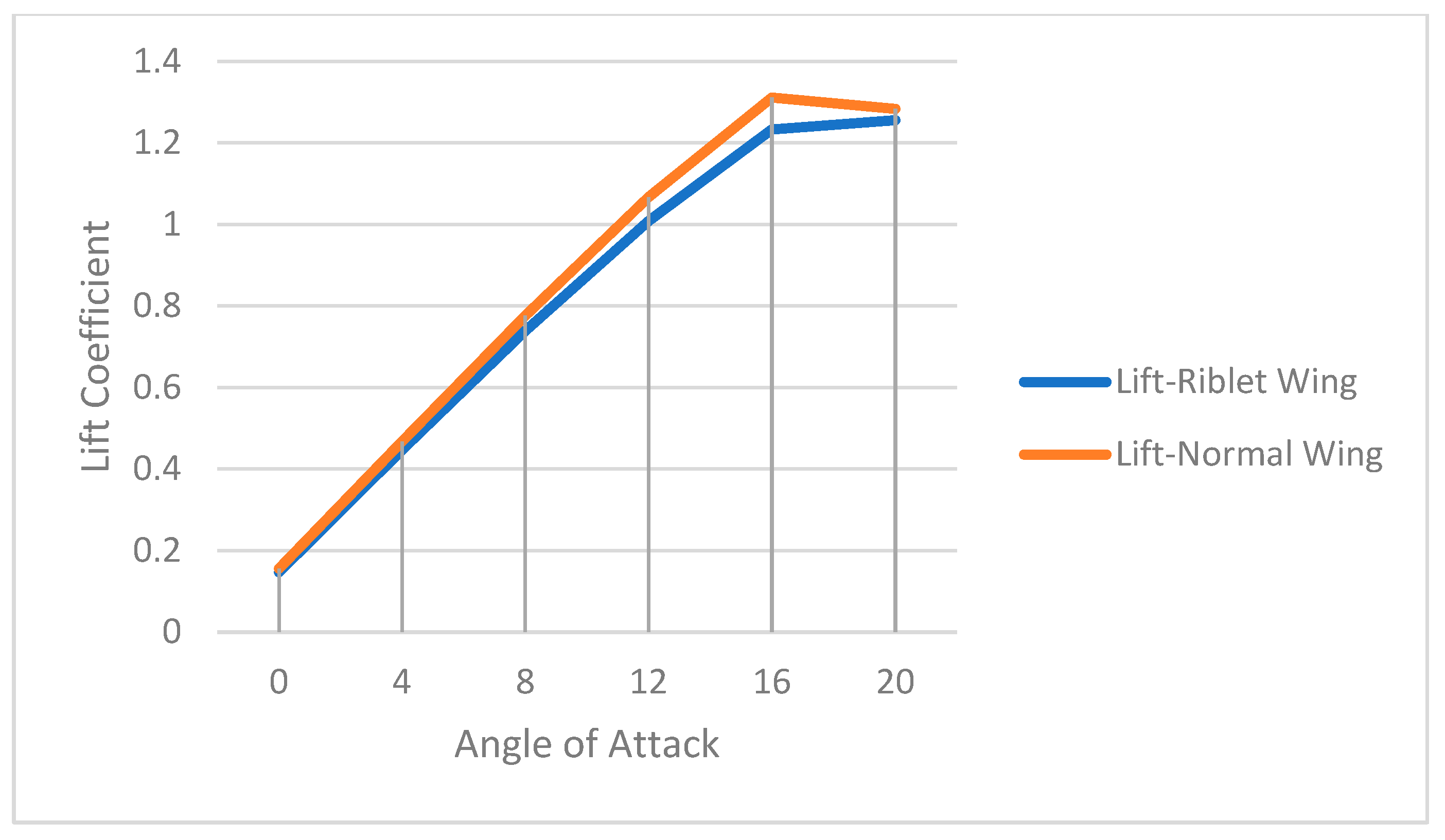
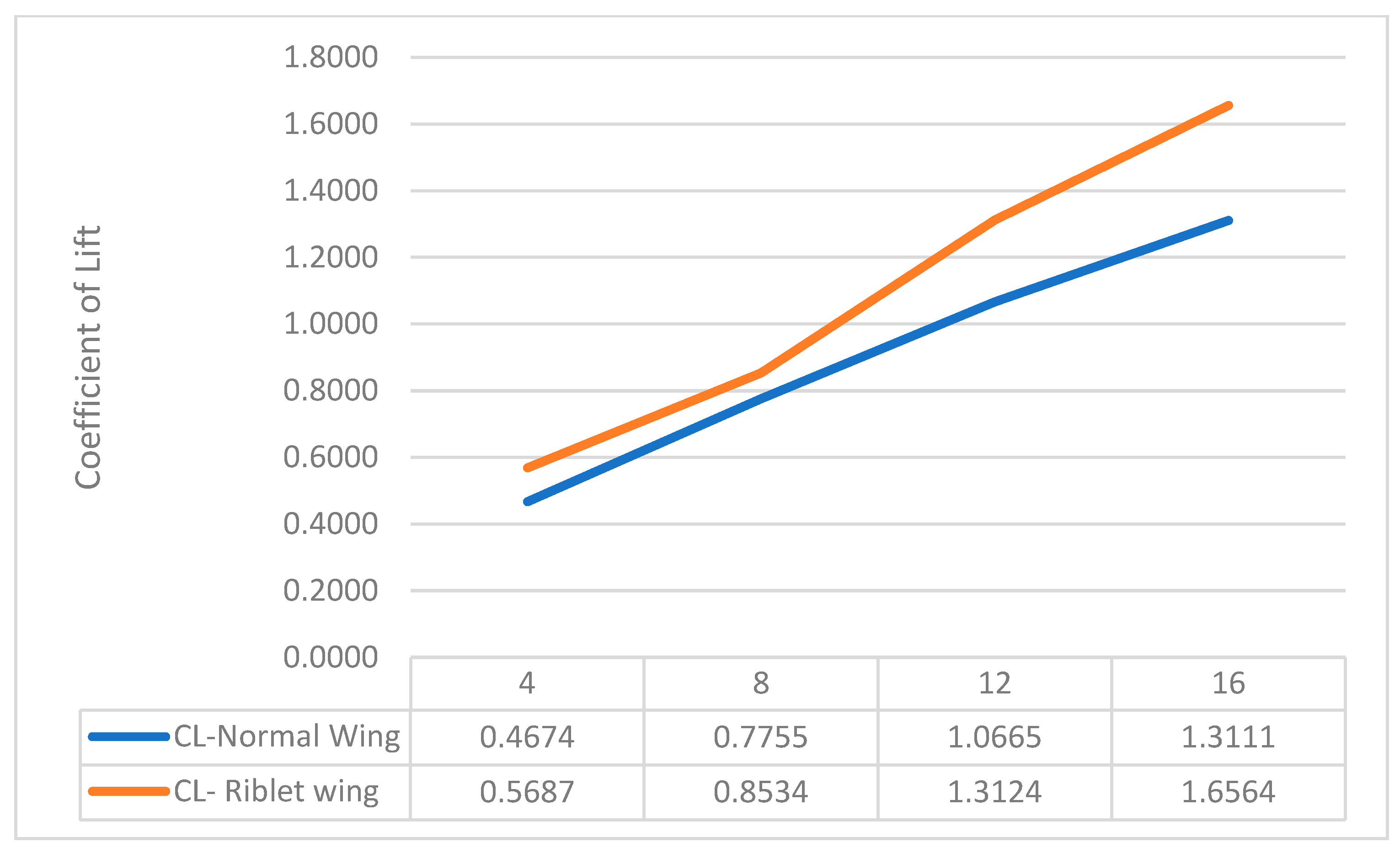
Several studies demonstrate that symmetrical V-shaped riblets have the capability to enhance lift [51]. Therefore, the V-shaped riblets were placed at the midsection of the wingspan, ranging from the 0.3C to 0.95C chord position. However, this did not improve the lift coefficients as expected (shown in Figure 10) due to variations in the height, spacing between the riblet tips, utilization of lower stream velocities, and riblet dimensions when compared to the referenced literature [51]. As a result, a change was made by relocating the riblets from midspan to three different positions, as depicted in Figure 3 under the computational design section. Identical meshing and analysis approaches were adopted for this modified configuration, which resulted in improved lift values, as shown in Figure 11. A substantial lift enhancement of 19%, 9%, and 20% were noted at the 4°, 8°, and 12° angles of attack, respectively. Moreover, a remarkable lift increment of 23% was achieved at the 16° angle of attack.
It is essential to point out that the results may vary at different flow conditions, as the pressure distribution varies at different flow speeds. Additionally, it is not possible to generalize the results obtained for all 3D aerofoils, as the chord and camber varies from one aerofoil to another.

6. Validation

6.1. Method Validation

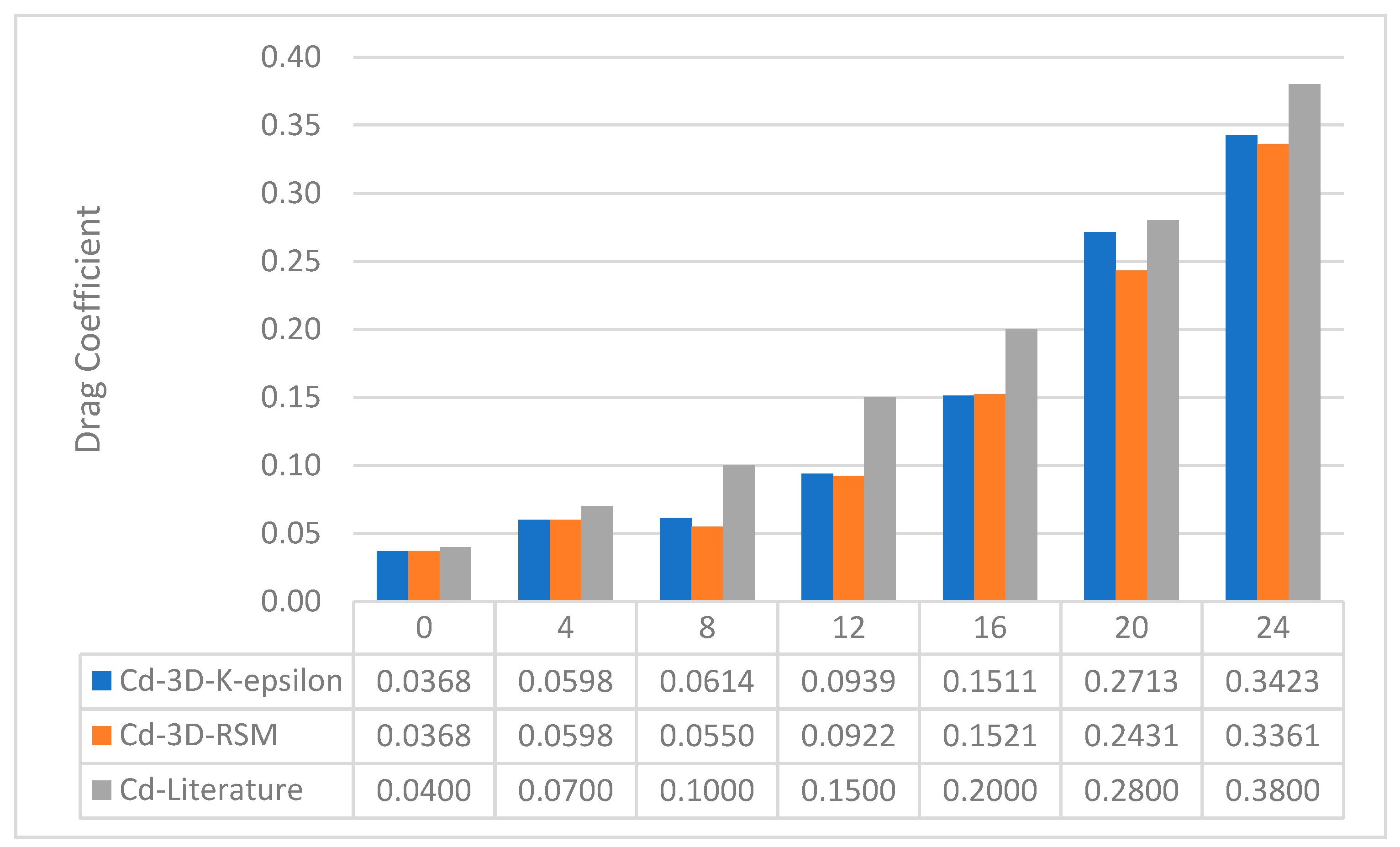
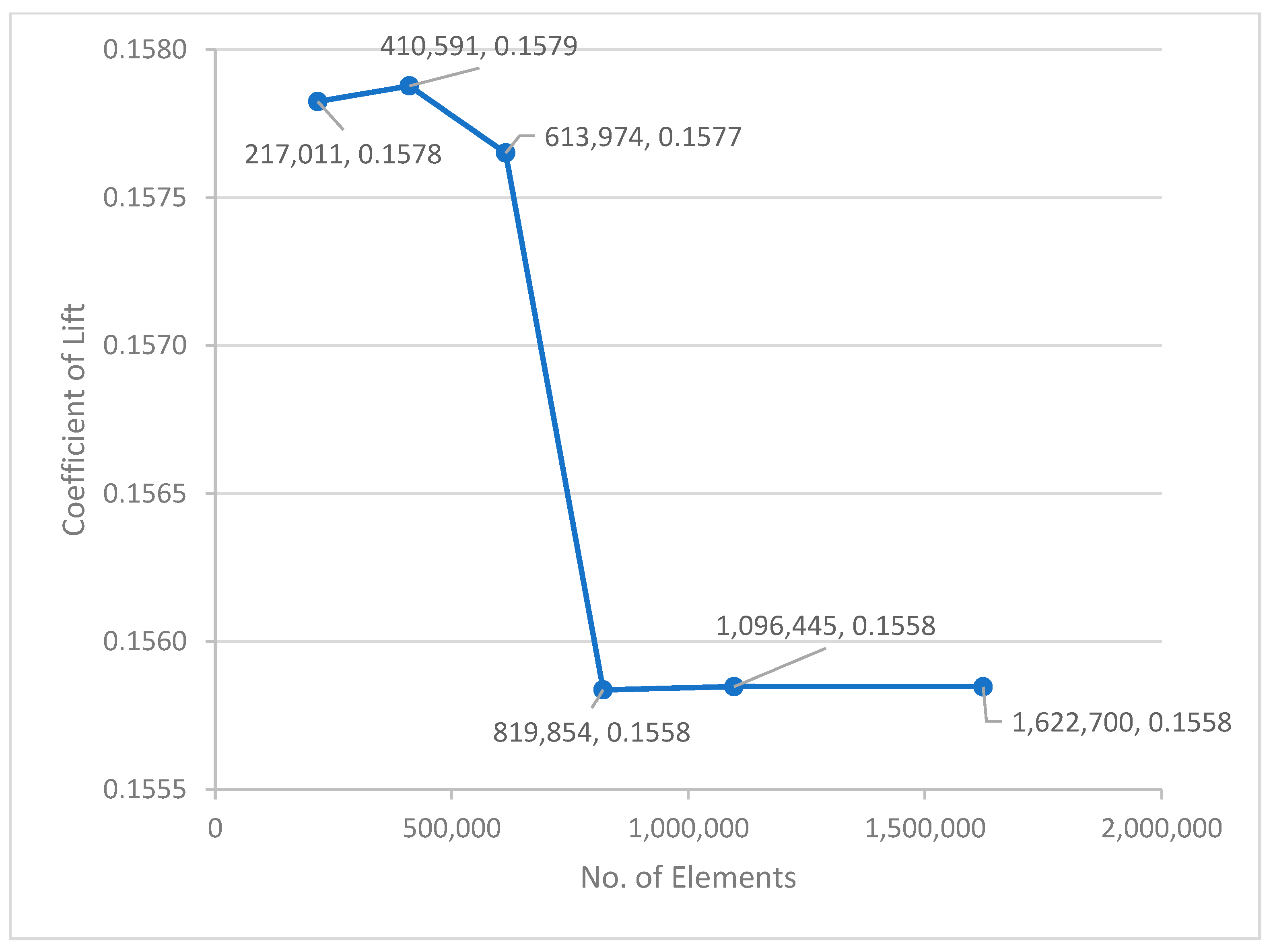
It is essential to verify the computational method used in this research project. Hence, relevant literature [24] (where the actual lift and drag values were noted) was taken as a reference to validate the same method at the start of this project. A 3D design of the NACA 2412 wing was developed and analysed in airflow using the K-epsilon and the RSM models, similar to the procedure used in the reference journal. Mesh convergence was achieved at 819,854 elements, which is very close to the number of elements (fewer than 800,000 elements) noted in the reference journal/literature.
In terms of drag coefficient, similar values were obtained at the 0° and 4° angles of attack, as shown in Figure 12. For example, at 4°, 0.059 and 0.065 drag coefficients were noted in the recreated design and the literature. Although slightly deviated values were observed at the 8°, 12°, and 16° angles of attack, still those values are within the acceptable range. This verifies that the computational method used in this project is reliable and relatable, as the results are validated against actual values.

6.2. Mesh Validation

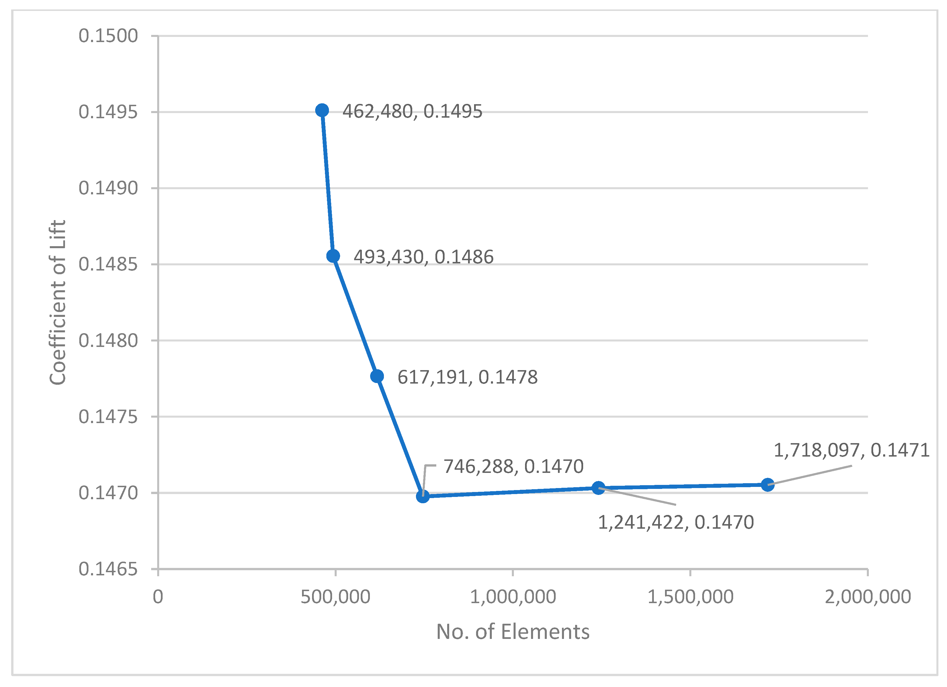
For precise findings, an ideal grid design is needed, and to create the best grid, the grid independence test is typically run [52]. Thus, it was performed for the validation of the NACA2412 aerofoil in 3D. The mesh element size was changed repeatedly to obtain a stable value for the lift coefficient. Figure 13 interprets the lift coefficient noted at different mesh element sizes. Exactly six mesh independence studies (MISs) were carried out to obtain the expected results. Two MISs were performed under 50,000 elements, which resulted in different lift coefficients. Another two MISs were performed between 50,000 and 100,000 elements and obtained unstable results. Finally, the solution reached a state of stability, resulting in a lift coefficient of 0.18, obtained with 819,854 elements for a smooth wing, as shown in Figure 14. Similarly, an MIS was performed for the riblet wing, as shown in Figure 14, and noted stable results. The elements that showed stable results (in normal and riblet wings) were used in this research project.

7. Conclusions

The drag reduction efficiency of a V-shaped triangular-type riblet was studied with a pressure-based solver in turbulent flow. Computational analysis was performed at different angles of attack, and the results were compared. The riblet design at the centre of the wingspan from the 0.3 to 0.95 chord position showed effective drag reduction from 5.7 to 15.6% at several angles of attack. This experiment aimed to enhance lift by incorporating riblets in three distinct locations across the wingspan, resulting in improved lift values between 9 and 23% at many angles of attack. The computational method and mesh were validated using appropriate techniques. The optimal drag reduction effect was achieved with a riblet h/s ratio of 0.8 for the chosen NACA wing.

Author Contributions

Conceptualization, S.M.S. and S.M.; methodology, S.M.S.; software, S.M.S. and S.M.; validation, S.M.S., S.M. and A.W.A.; formal analysis, S.M.; investigation, A.W.A.; resources, S.M.S.; data curation, K.D. and S.M.; writing—original draft preparation, S.M.S.; writing—review and editing, K.D., A.W.A. and S.M.; supervision, S.M. and A.W.A. All authors have read and agreed to the published version of the manuscript.

Funding

This research received no external funding.

Institutional Review Board Statement

Not applicable.

Informed Consent Statement

Not applicable.

Data Availability Statement

The datasets used and/or analysed during the current study are available from the corresponding author upon reasonable request.

Acknowledgments

The authors thank Staffordshire University for providing the research facilities to complete this project.

Conflicts of Interest

The authors declare no conflicts of interest.

References

  1. Babikian, R.; Lukachko, S.P.; Waitz, I.A. The historical fuel efficiency characteristics of regional aircraft from technological, operational, and cost perspectives. J. Air Transp. Manag. 2002, 8, 389–400. [Google Scholar] [CrossRef]
  2. Kuhn, H.; Falter, C.; Sizmann, A. Renewable Energy Perspectives for Aviation [Preprint]. In Proceedings of the 3rd CEAS Air & Space Conference, Venice, Italy, 24–28 October 2011. [Google Scholar]
  3. Hendrickson, R.; Grumman; Roman, D.; Rajkovic, D. 5. Drag: An Introduction—Virginia Tech, 5. Drag: An Introduction. 1997; Available online: https://archive.aoe.vt.edu/mason/Mason_f/CAtxtChap5.pdf (accessed on 14 August 2023).
  4. Timmer, W.A.; Bak, C. Aerodynamic characteristics of wind turbine blade airfoils. In Advances in Wind Turbine Blade Design and Materials; Book Chapter; Elsevier: Amsterdam, The Netherlands, 2023; pp. 129–167. [Google Scholar] [CrossRef]
  5. Belligoli, Z.; Koers, A.J.; Dwight, R.P.; Eitelberg, G. Using an anti-fairing to reduce drag at wing/body junctions. AIAA J. 2019, 57, 1468–1480. [Google Scholar] [CrossRef]
  6. Beratlis, N.; Squires, K.D.; Balaras, E. Separation control and drag reduction using roughness elements. In Proceedings of the Tenth International Symposium on Turbulence and Shear Flow Phenomena, Chicago, IL, USA, 7–9 July 2017. [Google Scholar] [CrossRef]
  7. Rajasai, B.; Tej, R.; Srinath, S. Aerodynamic effects of dimples on Aircraft Wings. In Proceedings of the Fourth International Conference on Advances in Mechanical, Aeronautical and Production Techniques—MAPT, Kuala Lumpur, Malaysia, 27 September 2015. [Google Scholar] [CrossRef]
  8. Reneaux, J. Overview on drag reduction technologies for civil transport aircraft. In Proceedings of the European Congress on Computational Methods in Applied Sciences and Engineering (ECCOMAS), Jyväskylä, Finland, 24–28 July 2004; Neittaanmäki, P., Rossi, T., Korotov, S., Oñate, E., Périaux, J., Knörzer, D., Eds.; [Google Scholar]
  9. Merryisha, S.; Rajendran, P. Experimental and CFD Analysis of Surface Modifiers on Aircraft Wing: A Review. CFD Lett. 2019, 11, 46–56. [Google Scholar]
  10. Zhou, Y.; Wang, Z.J. Effects of surface roughness on separated and transitional flows over a wing. AIAA J. 2012, 50, 593–609. [Google Scholar] [CrossRef]
  11. Hövelmann, A.; Knoth, F.; Breitsamter, C. AVT-183 diamond wing flow field characteristics part 1: Varying leading-edge roughness and the effects on flow separation onset. Aerosp. Sci. Technol. 2016, 57, 18–30. [Google Scholar] [CrossRef]
  12. Kurz, H.B.E.; Kloker, M.J. Discrete-roughness effects in a three-dimensional boundary layer on an airfoil by means of DNS. Procedia IUTAM 2015, 14, 163–172. [Google Scholar] [CrossRef]
  13. Bari, A.A.; Mashud, M.; Ali, H. Role of partially bumpy surface to control the flow separation of an airfoil. ARPN J. Eng. Appl. Sci. 2012, 7, 584–587. [Google Scholar]
  14. Lang, A.; Habegger, M.L.; Motta, P. Shark skin drag reduction. In Encyclopedia of Nanotechnology; Springer: Dordrecht, The Netherlands, 2016; pp. 3632–3639. [Google Scholar] [CrossRef]
  15. Marimuthu, S.; Chinnathambi, D. Computational analysis of biomimetic butterfly valve. Bioinspired Biomim. Nanobiomater. 2020, 9, 223–232. [Google Scholar] [CrossRef]
  16. Marimuthu, S.; Chinnathambi, D. Computational analysis to enhance the compressible flow over an aerofoil surface. Aircr. Eng. Aerosp. Technol. 2021, 93, 925–934. [Google Scholar] [CrossRef]
  17. Marimuthu, S.; Al-Rabeei, S.; Boha, H.A. Three-dimensional analysis of biomimetic aerofoil in transonic flow. Biomimetics 2022, 7, 20. [Google Scholar] [CrossRef]
  18. Marimuthu, S.; Natarajan, M.; Ramesh, R.; Murugesan, R. Hollow three-dimensional model for fuel reduction in aviation industry. Int. J. Interact. Des. Manuf. 2022, 1–11. [Google Scholar] [CrossRef]
  19. Marimuthu, S.; Murugan, M.A.; Sivasathya, U.; Dharmalingham, S. Biomimetic in Turbulence reduction-Recent Developments. J. Appl. Sci. Res. 2015, 11, 123–134. Available online: https://ssrn.com/abstract=3196017 (accessed on 22 August 2023).
  20. Fraser, G.J. Shark Study Reveals Taste Buds Were Key to Evolution of Teeth, The Conversation. 2022. Available online: https://theconversation.com/shark-study-reveals-taste-buds-were-key-to-evolution-of-teeth-71376 (accessed on 3 November 2023).
  21. Kumaar, R.K.; Maniiarasan, P. Reduction of skin friction drag in wings by employing riblets. Int. J. Eng. Res. Technol. 2015, 4, 46–51. [Google Scholar] [CrossRef]
  22. Bixler, G.D.; Bhushan, B. Biofouling: Lessons from nature. Philos. Trans. R. Soc. A Math. Phys. Eng. Sci. 2012, 370, 2381–2417. [Google Scholar] [CrossRef]
  23. Tullis, S.; Pollard, A. Modelling the time dependent flow over riblets in the Viscous Wall Region. Appl. Sci. Res. 1993, 50, 299–314. [Google Scholar] [CrossRef]
  24. Ives, R.; Keir, S.; Bassey, E.; Hamad, F.A. Investigation of the flow around an aircraft wing of section NACA 2412 utilising ANSYS fluent. INCAS Bull. 2018, 10, 95–104. [Google Scholar] [CrossRef]
  25. Jacobs, E.N.; Ward, K.E.; Pinkerton, R.M. The Characteristics of 78 Related Aerofoil Sections from Tests in the Variable-Density Wind Tunnel. In Report National Advisory Committee for Aeronautics; National Advisory Committee for Aeronautics: Washington, DC, USA, 1933; pp. 299–354. [Google Scholar]
  26. Mukesh, M.; Arun, M.D.; Divyasharada, N.S.; Prakash, K.; Ram Rakshith, V. Experimental and Numerical Analysis of Rectangular, Tapered and Tapered Swept Back wings. Int. Res. J. Eng. Technol. 2019, 6, 7245–7348. [Google Scholar]
  27. Chakroun, W.; Al-Mesri, I.; Al-Fahad, S. Effect of surface roughness on the aerodynamic characteristics of a symmetrical aerofoil. Wind Eng. 2004, 28, 547–564. [Google Scholar] [CrossRef]
  28. Heidarian, A.; Ghassemi, H.; Liu, P. Numerical Analysis of the effects of riblets on drag reduction of a flat plate. J. Appl. Fluid Mech. 2018, 11, 679–688. [Google Scholar] [CrossRef]
  29. Zhang, Y.; Yan, C.; Chen, H.; Yin, Y. Study of riblet drag reduction for an infinite span wing with different sweep angles. Chin. J. Aeronaut. 2020, 33, 3125–3137. [Google Scholar] [CrossRef]
  30. Soleimani, S.; Eckels, S. A review of drag reduction and heat transfer enhancement by Riblet surfaces in closed and open channel flow. Int. J. Thermofluids 2021, 9, 100053. [Google Scholar] [CrossRef]
  31. Sijal. [Ansys Meshing] c or O Domain for Aerofoil Analysis? CFDonline.com. 2012. Available online: https://www.cfd-online.com/Forums/ansys-meshing/108595-c-o-domain-aerofoil-analysis.html (accessed on 16 August 2023).
  32. LEAP CFD Team. Tips & Tricks: Size Controls in Ansys, Computational Fluid Dynamics CFD Blog LEAP Australia New Zealand. 2020. Available online: https://www.computationalfluiddynamics.com.au/size-controls/ (accessed on 21 August 2023).
  33. Sosnowski, M.; Krzywanski, J.; Grabowska, K.; Gnatowska, R. Polyhedral meshing in numerical analysis of conjugate heat transfer. EPJ Web Conf. 2018, 180, 02096. [Google Scholar] [CrossRef]
  34. ANSYS. Near-Wall Mesh Guidelines, Ansys Fluent 12.0 Theory Guide—12.3.1 Near-Wall Mesh Guidelines. 2009. Available online: https://www.afs.enea.it/project/neptunius/docs/fluent/html/ug/node410.htm (accessed on 18 August 2023).
  35. ANSYS. Standard Wall Functions, Ansys Fluent 12.0 Theory Guide—4.12.2 Standard Wall Functions. 2009. Available online: https://www.afs.enea.it/project/neptunius/docs/fluent/html/th/node99.htm (accessed on 18 August 2023).
  36. Simscale. Mesh Quality, Simscale. 2022. Available online: https://www.simscale.com/docs/simulation-setup/meshing/mesh-quality/ (accessed on 18 August 2023).
  37. PRACE. Partnership for Advanced Computing in Europe, Express Introductory Training in ANSYS Fluent. 2012. Available online: https://events.prace-ri.eu/event/156/contributions/14/attachments/70/102/Fluent-Intro_14.5_WS01_Mixing_Tee.pdf (accessed on 18 August 2023).
  38. Andrade, S.d.S. Understanding and Applying Boundary Conditions in CFD: Diabatix, Heat Sink Generative Design Software. 2023. Available online: https://www.diabatix.com/blog/understanding-and-applying-boundary-conditions-in-cfd (accessed on 22 August 2023).
  39. Zawawi, M.H.; Saleha, A.; Salwa, A.; Hassan, N.H.; Zahari, N.M.; Ramli, M.Z.; Muda, Z.C. A review: Fundamentals of Computational Fluid Dynamics (CFD). AIP Conf. Proc. 2018, 2030, 020252. [Google Scholar] [CrossRef]
  40. Bihs, H. What Is Advantage of SIMPLE Algorithm? Cfdonline. 2010. Available online: https://www.cfd-online.com/Forums/main/76202-what-advantage-simple-algorithm.html (accessed on 21 August 2023).
  41. Telenta, M.; Šubelj, M.; Tavčar, J.; Duhovnik, J. Detached Eddy Simulation of the flow around a simplified vehicle sheltered by wind barrier in transient yaw crosswind. Mechanika 2015, 21, 193–200. [Google Scholar] [CrossRef]
  42. Goyal, S.; Kulshreshtha, A.; Singh, S. Selection of Turbulence Model for Analysis of Aerofoil Wing using CFD. Int. Res. J. Eng. Technol. (IRJET) 2021, 8, 2608–2614. [Google Scholar]
  43. Chaudhry, A.U. Fundamentals of Reservoir Oil Flow Analysis. In Oil Well Testing Handbook; Elsevier: Burlington, VT, USA, 2004; pp. 13–43. [Google Scholar] [CrossRef]
  44. LearnCAx. Basics of Y Plus Boundary Layer and Wall Function in Turbulent Flows, LearnCAx. 2022. Available online: https://www.learncax.com/knowledge-base/blog/by-category/cfd/basics-of-y-plus-boundary-layer-and-wall-function-in-turbulent-flows (accessed on 22 August 2023).
  45. SimScale. K-Epsilon Turbulence Model: Global Settings, SimScale. 2023. Available online: https://www.simscale.com/docs/simulation-setup/global-settings/k-epsilon/#:~:text=It%20is%20a%20two%2Dequation,and%20diffusion%20of%20turbulent%20energy (accessed on 4 October 2023).
  46. Crocker, M.J. Handbook of Acoustics; Wiley: New York, NY, USA, 1998. [Google Scholar]
  47. Lissaman, P.B.S. Low-Reynolds-Number Aerofoils [Preprint]; Annual Reviews: San Mateo, CA, USA, 1983. [Google Scholar]
  48. Saarlas, M. Aircraft Performance; John Wiley & Sons: Hoboken, NJ, USA, 2007. [Google Scholar]
  49. SimScale, S.D. What Is Drag Coefficient?: SimWiki, SimScale. 2023. Available online: https://www.simscale.com/docs/simwiki/lift-drag-pitch/what-is-drag-coefficient/ (accessed on 2 May 2024).
  50. Konovalov, S.F.; Lashkov, Y.A.; Mikhailov, V.V. Effect of riblets on the drag of a body of revolution with trailing-edge flow separation. Fluid Dyn. 1998, 33, 135–139. [Google Scholar] [CrossRef]
  51. Geng, Z.; Cai, J.; Jiang, Y.; Zhang, W. On aircraft lift and drag reduction using V shaped riblets. Fluid Dyn. Mater. Process. 2021, 17, 899–915. [Google Scholar] [CrossRef]
  52. Lee, M.; Park, G.; Park, C.; Kim, C. Improvement of grid independence test for computational fluid dynamics model of building based on Grid Resolution. Adv. Civ. Eng. 2020, 2020, 8827936. [Google Scholar] [CrossRef]
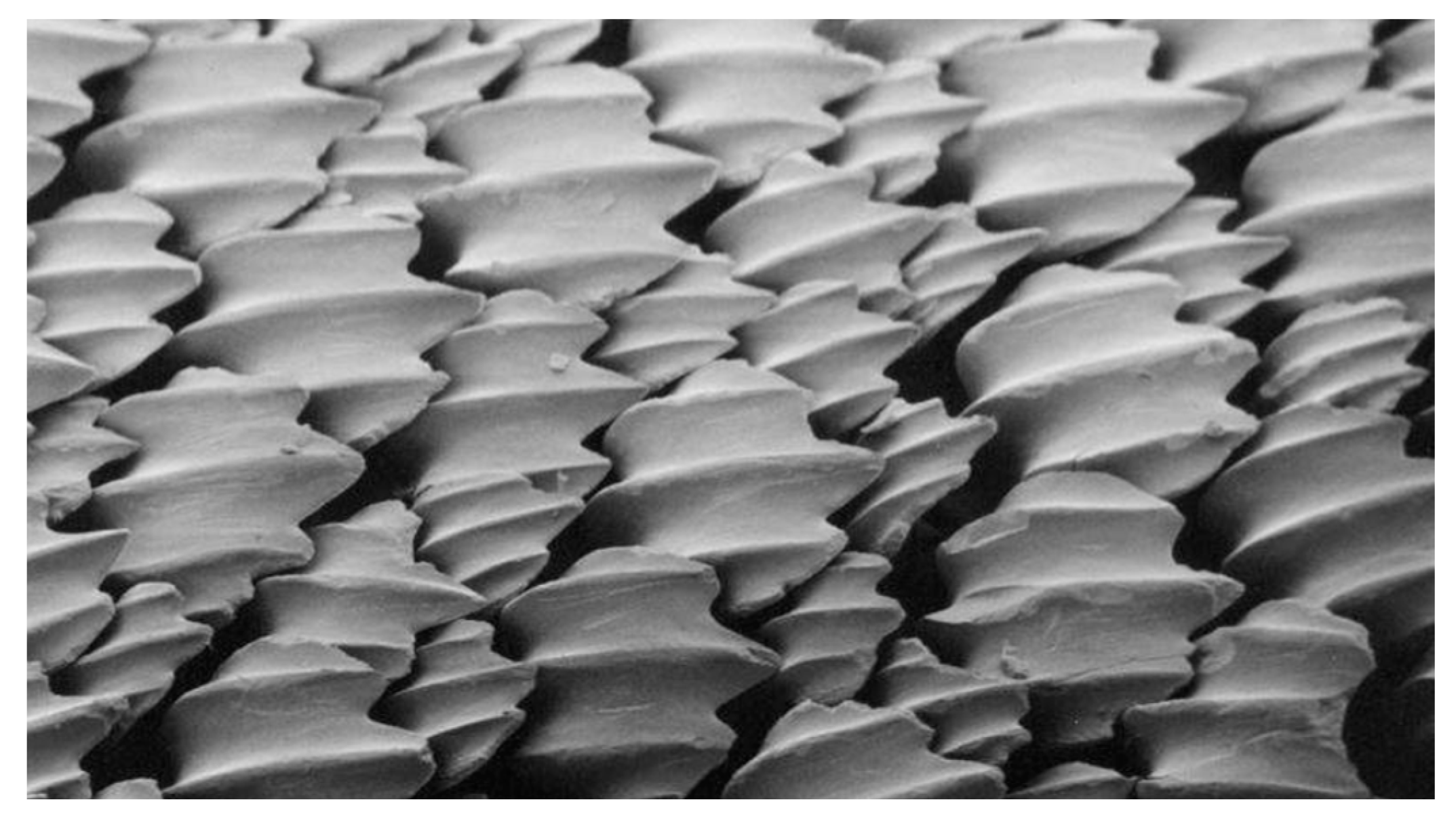
Figure 1. Riblets on shark skin [20].
Eng 05 00051 g001
Figure 2. Riblets at the centre of the wingspan.
Eng 05 00051 g002
Figure 3. Riblets at three different places of the wingspan.
Eng 05 00051 g003
Figure 4. Riblet dimensions.
Eng 05 00051 g004
Figure 5. Three-dimensional fluid domain.
Eng 05 00051 g005
Figure 6. Mesh—wing with riblets.
Eng 05 00051 g006
Figure 9. Velocity vector at 0° angle of attack for riblet wing.
Eng 05 00051 g009
Figure 10. Lift coefficient—normal vs. midspan-riblet wings.
Eng 05 00051 g010
Figure 11. Lift coefficient—normal vs. three-riblet wings.
Eng 05 00051 g011
Figure 12. Drag coefficient—reference literature vs. recreated design values.
Eng 05 00051 g012
Figure 13. Mesh independence study—normal wing.
Eng 05 00051 g013
Figure 14. Mesh independence study—riblet wing.
Eng 05 00051 g014
Disclaimer/Publisher’s Note: The statements, opinions and data contained in all publications are solely those of the individual author(s) and contributor(s) and not of MDPI and/or the editor(s). MDPI and/or the editor(s) disclaim responsibility for any injury to people or property resulting from any ideas, methods, instructions or products referred to in the content.