Review

Direct Air Capture (DAC) for Achieving Net-Zero CO2 Emissions: Advances, Applications, and Challenges

1
College of Engineering and Physical Sciences, University of Wyoming, Laramie, WY 82071, USA
2
School of Engineering and Applied Science, University of Pennsylvania, Philadelphia, PA 19104, USA
3
Biodesign Institute, Arizona State University, Tempe, AZ 85287, USA
*
Author to whom correspondence should be addressed.
Eng 2024, 5(3), 1298-1336; https://doi.org/10.3390/eng5030069
Submission received: 15 June 2024 / Revised: 3 July 2024 / Accepted: 3 July 2024 / Published: 4 July 2024
(This article belongs to the Special Issue Green Engineering for Sustainable Development 2024)

Abstract

:
Carbon dioxide (CO2), as the primary greenhouse gas, has significant impacts on global climate change, leading to severe and irreversible adverse consequences for ecosystems and human environments. To address the issue of excessive CO2 emissions, efforts in recent years have yielded significant progress in the development of clean energy sources and the promotion of carbon capture, utilization, and storage (CCUS) technologies. Conventional CO2 capture techniques are limited in addressing global atmospheric CO2 excess effectively, as they target only high-concentration CO2 emissions and require implementation at specific emission points. Direct air capture (DAC) technology has emerged as a promising solution due to its flexibility in deployment, avoidance of land competition, and ability to capture legacy CO2 emissions. Additionally, DAC offers opportunities for producing synthetic clean fuels, thereby reducing reliance on traditional fossil fuels and aiding in reducing greenhouse gas emissions. This study provides a comprehensive review of DAC technology, encompassing its principles, technological advancements, real-world applications, challenges, and future research directions. By offering insights into the current state and potential of DAC technology, this study aims to guide global efforts in scaling up DAC deployment, ultimately contributing to achieving global carbon neutrality or even negative emissions.

Graphical Abstract

1. Introduction

Greenhouse gases, especially carbon dioxide (CO2), have significant impacts on global climate change, leading to rising global temperatures, rising sea levels, and increased frequency of extreme weather events [1]. These effects have brought about long-term, severe, and irreversible consequences for ecosystems and human living environments [2]. Over the past two decades, the issue of excessive CO2 emissions has become increasingly significant, driven by rapid global economic development [3,4]. The global greenhouse gas emissions primarily come from four main sectors: energy (73.2%); agriculture, forestry, and land use (18.4%); industry (5.2%); and waste (3.2%) [5]. The breakdown of these categories into subcategories is illustrated in Figure 1. Energy, as a broad category contributing to the largest greenhouse gas emissions, includes subcategories such as energy used in industry (24.2%), buildings (17.5%), transport (16.2%), unallocated fuel combustion (7.8%), fugitive emissions from energy production (5.8%), and agriculture and fishing energy (1.7%) [5], all of which are closely intertwined with aspects of daily life.
While fossil fuels are dominant energy resources worldwide due to their availability and low cost [6,7,8,9], the production and combustion of fossil fuels are the primary causes of excessive CO2 emissions, exacerbating the adverse effects of greenhouse gases [2]. Mining operations, whether for fossil fuels or other minerals and metals, typically rely heavily on machinery powered by fossil fuels for drilling, blasting, hauling, processing, and subsequent transportation. All of these processes cause direct and indirect greenhouse gas emissions, resulting in a significant carbon footprint [10,11]. To address this issue, carbon tax has been used as a method to incentivize mining industries to reduce their carbon footprint by imposing a price on carbon emissions [12]. This approach helps align economic activities with environmental goals by internalizing the costs of carbon pollution and promoting sustainable practices. The interrelation of environmental and economic factors that influence technologies to achieve production efficiency, job creation, and environmental load reduction is crucial [13,14].
The problems caused by excessive CO2 emissions have gained worldwide attention. In response, the United Nations has formulated and enacted the United Nations Framework Convention on Climate Change (UNFCCC) [15]. The UNFCCC aims to establish a common political framework and cooperation platform, enabling the international community to coordinate efforts globally, collectively address climate change challenges, and promote the formulation and implementation of international climate policies. In 2015, global leaders adopted the Paris Agreement, which aims to limit the increase in global average temperature to within 2 °C above pre-industrial levels, with efforts to keep it below 1.5 °C [16]. To achieve this goal, countries have actively formulated and announced emission reduction targets and action plans.
In recent years, significant progress has been made in the development of clean energy sources such as solar power [17,18,19], nuclear energy [20,21], and wind power [22,23]. This has helped alleviate the issue of CO2 emissions to some extent. Additionally, the promotion of carbon capture, utilization, and storage (CCUS) technology has become one of the important measures adopted by various countries to address this challenge [2,24,25]. CCUS technology primarily involves the capture and separation of CO2 emitted during industrial production. Subsequently, the captured CO2 is transported via pipelines or trucks and stored in designated locations for either utilization or permanent sequestration. Currently, widely used capture technologies mainly focus on capturing CO2 from sources such as refineries and power plants, which typically have higher concentrations of CO2, thus facilitating higher capture efficiency. However, the target of these capture techniques is limited only to high-concentration CO2 emissions and requires implementation at specific emission points, making them unable to comprehensively address the issue of excess CO2 in the atmosphere globally.
Direct air capture (DAC) technology, on the other hand, can overcome some of the limitations of conventional capture methods and is the most direct way to reduce carbon concentrations in the atmosphere [26,27]. Unlike conventional CCUS technologies that focus on capturing CO2 from fixed emission sources, DAC facilities do not need to be connected to emission points. Therefore, they can be deployed in more locations than CCUS facilities, providing geographical flexibility and wider applicability. Additionally, DAC’s deployment does not require precious arable land, thereby avoiding competition with the agriculture or bioenergy sectors for land use [26]. Moreover, DAC has the ability to capture low-concentration CO2 that was released years ago but still persists in the atmosphere, making it a method to address legacy CO2 emissions [2,26]. Furthermore, DAC technology can create synthetic clean fuels by combining captured carbon with clean hydrogen, enabling the production of synthetic hydrocarbon fuels [28]. These fuels, which can account for up to 40% of aviation fuel demand, can replace traditional fossil fuels such as oil, natural gas, and coal, thereby reducing greenhouse gas emissions. Therefore, DAC technology is considered by the International Energy Agency (IEA) to be one of the key technologies for achieving net-zero or negative emissions [26]. Given these significant advantages, DAC technology is poised for widespread global adoption, providing countries and regions with a universal pathway for carbon reduction and contributing to the achievement of broader carbon neutrality goals.
Given the significant impact and importance of DAC, research and application of DAC technology have become key focal points in international scientific research and efforts in recent years. According to the IEA report, to achieve a sustainable development scenario globally, it is anticipated that an average of 32 DAC plants, each capable of capturing 1 Mt CO2/year, will be added annually from 2020 to 2050 [26]. However, the deployment of DAC technology still faces certain limitations. These include cost competitiveness with other mitigation measures, potential constraints on appropriate storage facilities, and limitations due to the availability of low-cost electricity and thermal energy for the continuous operation of DAC facilities. To address these challenges, governments, businesses, and research institutions worldwide are investing resources to drive innovation and development of DAC technology. Accomplishments in research related to DAC technology, spanning multiple disciplines and fields (such as materials science, chemical engineering, environmental science, and energy), have been made in improving the capture efficiency and reducing the cost of DAC technology [27,29,30,31,32,33]. In terms of practical application, some countries have initiated pilot DAC projects in the industrial and energy sectors [26]. Although many of these DAC projects are still small-scale, some have grown to commercial scale utilizing mature and refined DAC technology.
This study presents a comprehensive overview of DAC. It commences with an introduction to the fundamental principle of DAC, followed by an in-depth exploration of three categories of DAC technologies: liquid DAC (L-DAC), solid DAC (S-DAC), and emerging DAC technologies. Subsequently, it examines the current real-world applications of DAC technology worldwide. Building upon this foundation, this study identifies the challenges and future research directions facing DAC. The significance of this review lies in providing a comprehensive understanding of DAC technology, offering crucial information on integrated technological advancements and real-world applications to the scientific community, industry stakeholders, and policymakers. It serves as a platform for scholars worldwide to gain in-depth insights into the forefront of integrated technology. This study aims to guide global DAC technology and operations, promoting its broader adoption and contributing to the achievement of global carbon neutrality or even negative emissions targets.

2. Data Collection and Methodology

This study was conducted through a systematic approach encompassing literature collection, categorization, analysis, and summary. Information was sourced from a diverse range of academic research articles indexed in the Web of Science and Scopus databases, supplemented by data from the IEA, as well as relevant content from company and government reports. The timespan of the data collection ranged from 1990 to 2024. The collected information and data were systematically classified into two main categories: technological advancements, and practical applications. Each category underwent detailed analysis, subcategorization, and summarization. This methodological framework facilitated a thorough investigation of the current technological and application challenges in DAC research, enabling the identification of corresponding measures and potential future research directions.

3. Basic Principle of DAC

In 1999, Lackner et al. introduced the concept of extracting CO2 from the air [34], which evolved into direct air capture. Their research findings confirmed the effectiveness of this technology, which utilizes atmospheric transport to convey CO2 from its source to the disposal site, demonstrating its ability to control atmospheric CO2 levels without limiting access to fossil energy resources. It is noteworthy that DAC technology, along with other CO2 capture technologies such as pre-combustion capture, post-combustion capture, and oxy-fuel combustion capture, shares the common goal of capturing CO2, but each possesses distinct applicable conditions, advantages, and disadvantages, as summarized in Table 1. Pre-combustion capture, post-combustion capture, and oxy-fuel combustion capture are typically designed for high-concentration CO2 and are therefore primarily utilized in power plants [2]. In contrast, DAC technology is tailored for capturing low-concentration CO2 from the atmosphere, enhancing its flexibility in deployment. However, the significant advantage of the other three capture technologies lies in their higher technological maturity compared to DAC. Moreover, they can be directly integrated into existing power plants, thereby significantly reducing initial investment costs compared to DAC. Meanwhile, DAC processes entail higher operating costs in terms of the energy and resources needed to capture equivalent amounts of CO2, primarily due to the low concentration of CO2 in ambient air. These technological limitations and higher costs have hindered extensive research and development of DAC since its proposal. Recently, DAC technology, as a key technology for negative carbon emissions, has gradually gained more attention. Table 2 presents several review studies summarizing research related to DAC, along with their main contents.
Although the focus of these DAC-related studies varies, there is a consensus on the three stages of CO2 capture in DAC: the contacting stage, the capture stage, and the separation stage, as illustrated in Figure 2. In the contacting stage, the DAC system transports atmospheric air containing CO2 to the equipment using large-scale fans. Subsequently, in the CO2 capture stage, CO2 rapidly and effectively binds with liquid solvents in chemical reactors or solid sorbents in filters, which must possess binding energies equivalent to that of CO2. Later, in the CO2 separation stage, external energy sources facilitate the separation of CO2 from the solvents or sorbents, yielding pure CO2 and regenerated solvents or sorbents. Following the completion of these three stages, the separated pure CO2 is either utilized or stored, while the recovered solvents or sorbents are recycled for reuse in the CO2 capture process.
It is worth noting that DAC facilities, which include large fans, reactors, filters, and separation units, rely on thermal and/or electrical energy sources for smooth operation. In recent years, to mitigate the carbon footprint of the CO2 capture process and reduce dependence on fossil fuels, it has been common to select clean or renewable energy sources as the energy supply for DAC facilities. Situating DAC facilities in proximity to clean or renewable energy sources helps reduce operational costs and maximizes their carbon removal potential. Additionally, locating DAC facilities near CO2 storage or utilization sites is also an option, facilitating a decrease in investments in pipeline infrastructure or fees associated with truck transportation for CO2 transport, thereby concurrently lowering operational costs while reducing the risk of CO2 leaks. These strategic placements optimize operational efficiency and cost-effectiveness, highlighting the potential of DAC facilities to achieve their objectives more effectively in the present era compared to their initial proposal.
Currently, liquid DAC (L-DAC) and solid DAC (S-DAC) represent two mature technologies for industrial deployment. Additionally, several emerging DAC technologies are in different stages of development, testing, or limited practical application. The following sections provide an in-depth exploration of the principles and technological advancements associated with these DAC techniques.

4. Liquid DAC (L-DAC)

4.1. Fundamental Principle of L-DAC

L-DAC stands out as the most mature among current DAC techniques. Its fundamental principle involves the initiation of chemical reactions driven by mass transfer between specific components of the solution and atmospheric CO2, resulting in the generation of specific chemical products [40,41]. Following treatment, the pure CO2 and regenerated solvent can be separated to achieve continuous operation. Notably, industrial implementations of L-DAC primarily employ alkaline solutions containing KOH or NaOH [41], with occasional utilization of Ca(OH)2 [42]. Figure 3 illustrates the process flow diagram, depicting two enclosed chemical loop processes.
In the first closed loop within the air contactor, CO2 is captured through contact with the solution. This process adheres to the principle of neutralization reactions between alkaline solutions and CO2, resulting in the formation of carbonates. These reactions selectively interact solely with CO2, effectively removing it from the air and fixing it within the solution as carbonate ions. The pertinent chemical reactions occurring during the CO2 capture process in the first loop, utilizing solutions primarily composed of KOH, NaOH, and Ca(OH)2, are illustrated by Reactions (1)–(3), respectively.
2 K O H ( a q ) + C O 2 ( g ) K 2 C O 3 ( a q ) + H 2 O ( l )
2 N a O H ( a q ) + C O 2 ( g ) N a 2 C O 3 ( a q ) + H 2 O ( l )
C a O H 2 a q + C O 2 g C a C O 3 s + H 2 O l
The second closed loop proceeds sequentially within the pellet reactor, calciner, and slaker, aiming to separate the captured CO2 and recover the solvent. In this process, for solutions employing KOH and NaOH, additional chemical substances (typically Ca(OH)2 in a solid slurry condition) are necessary. These substances further react with the carbonates generated in the first loop, obtaining solid calcium carbonate (CaCO3). Reactions (4) and (5) illustrate these reactions for KOH and NaOH solutions, respectively. Subsequently, the separated solid calcium carbonate undergoes high-temperature heating to decompose, yielding pure CO2 gas and solid calcium oxide (CaO), as depicted in Reaction (6). The solid calcium oxide further reacts with water to produce calcium hydroxide, as shown in Reaction (7), facilitating its reuse in this loop. If Ca(OH)2 solution is employed in the second separation loop, there is no need to add additional substances for reactions. Instead, direct heating is utilized to achieve CO2 separation and solvent regeneration, following Reactions (6) and (7). Despite offering simpler and more direct CO2 capture and separation operations, Ca(OH)2 solution is less commonly used due to its lower solubility in water compared to KOH and NaOH, resulting in a lower CO2 capture capacity.
K 2 C O 3 a q + C a O H 2 ( s ) C a C O 3 ( s ) + 2 K O H ( a q )
N a 2 C O 3 a q + C a O H 2 ( s ) C a C O 3 ( s ) + 2 N a O H ( a q )
C a C O 3 s C a O s + C O 2 ( g )
C a O s + H 2 O ( l ) C a O H 2 ( s )

4.2. Advantages and Disadvantages of L-DAC

The significant advantage of industrially utilized L-DAC technologies, primarily employing alkaline solutions as the principal component, lies in their ability to ensure continuous replenishment of the alkaline solution within large-scale contactors. This ensures uninterrupted and stable CO2 capture processes, eliminating the need for interruptions [26]. Following CO2 capture, its presence as carbonate ions within the solution facilitates its transfer to separate facilities for separation and regeneration without altering the conditions within the contactors used for capture, thus avoiding the need for cycling conditions within large-scale air contactors.
Capturing CO2 at room temperature or with minimal temperature increase is generally ideal, as it significantly reduces the energy consumption and costs associated with using fuel to produce heat. However, in the L-DAC process, it is necessary to use natural gas combustion to increase the operating temperature, which represents a significant disadvantage of this technology. Specifically, the reactions occurring in the air contactor and pellet reactor are completed at approximately 20 °C. In contrast, the reactions in the calciner and steam slaker require higher operating temperatures based on reaction thermodynamics and pilot data [41]. The calciner’s operating temperature needs to reach 900 °C, while the steam slaker requires an operating temperature of 300 °C. These high temperature requirements, along with the need for additional water sources for continuous solvent regeneration, increase the operational costs of L-DAC, representing a notable drawback. Additionally, due to the corrosive nature of strong alkaline solutions, equipment used in L-DAC typically requires corrosion-resistant materials such as stainless steels, nickel alloys, or specialized coatings capable of withstanding alkaline corrosion [44,45,46]. Implementing a rigorous maintenance schedule to regularly inspect equipment for signs of corrosion and wear is also essential to ensure longevity and reliability. These requirements underscore the heightened demands placed on equipment in L-DAC technology.

4.3. Technological Advancements of L-DAC

4.3.1. Advances in L-DAC Utilizing Alkaline Solutions

As the most mature DAC technology, L-DAC utilizing alkaline solutions has been commercially deployed on a large scale in several countries [40]. Recent significant advancements in this technology have focused on enhancing commercial-scale projects based on practical application scenarios. These advancements aim to achieve high capture efficiency while also controlling engineering costs to ensure the economic feasibility of L-DAC projects.
The efficiency of CO2 capture in L-DAC utilizing alkaline solutions is determined by the process occurring in the first loop within the contactor. In this loop, the alkaline solution flows vertically from top to bottom, while CO2 gas flows horizontally, perpendicular to the solution flow direction, creating a cross-flow pattern [47]. This pattern ensures efficient contact at the liquid surface, facilitating the capture of CO2 from the air on the thin film of the solution. The efficiency of CO2 capture is controlled by the diffusion of CO2 molecules into the solution and their subsequent reaction with the chemical substances in the solution [41]. Consequently, optimizing the diffusion and reaction processes has been a primary focus of recent advancements.
The optimization of the contactor is primarily based on core engineering constraints, ensuring that the design can efficiently bring large quantities of ambient air into contact with fluids. On this basis, Holmes and Keith proposed using a cost optimization model to evaluate cost trade-offs and determine optimal parameters, thus maximizing economic feasibility [47]. With the goal of capturing 1 MtCO2/year, they optimized the contactor structure and relevant parameters to effectively accelerate the diffusion and reaction processes of CO2. A simplified schematic of the air contactor’s structure is shown in Figure 4. It resembles industrial cooling towers [47,48], incorporating fans, structured packing, demisters, fluid distribution systems, and fiber-reinforced plastic structural components. The structured packing serves as a medium, with a large surface area to facilitate efficient contact between the air and a thin solution film for CO2 capture. Therefore, optimizing the structured packing to absorb a significant portion of CO2 from the air by minimizing frictional air resistance, while maintaining a low pressure drop to minimize the fan energy requirements at high air throughputs, is crucial for efficient CO2 diffusion and reaction processes. To achieve this, the structured packing’s air travel depth was optimized from the original 2–3 m to 7 m [41], significantly enhancing the contact efficiency between the solvent and air within the structured packing. Subsequent collaborative research by Grace et al. affirmed that, paired with the designed air velocity of 1.4 m/s, the optimized structured packing exhibited a pressure drop of 9.7 Pa/m during capture operations, notably reduced by over 30%, thereby decreasing the energy consumption [41].
In addition to the contactor’s structure, the efficiency of CO2 capture is influenced by the mass transfer coefficient of CO2 and the liquid-to-gas volumetric flow ratio. The mass transfer coefficient of CO2 determines the rate at which CO2 is transferred from the gas phase to the liquid phase during diffusion, primarily influenced by the concentration of hydroxide ions (OH) and the temperature of the solution. For well-wetted structured packing in industrial plants, Keith et al. estimated the mass transfer coefficient of CO2 to be approximately 1.3 mm/s under typical operating temperatures (20 °C), using a combination of semi-empirical formulae, empirical data, and modeling methods, with a typical solution composition of 1.0 M OH [41]. The liquid-to-gas volumetric flow ratio refers to the relative ratio of the liquid-phase volumetric flow rate to the gas-phase volumetric flow rate [49], describing their proportions within the contactor. Typically, a lower ratio, indicating less liquid per unit of gas, favors more thorough gas contact within the packing in the lower liquid flow regime, thereby enhancing the capture efficiency. Additionally, a reduced liquid-to-gas volumetric flow ratio signifies lower energy consumption for liquid pumping to achieve a low liquid flow rate, thereby mitigating energy costs to a certain extent [47]. However, it is crucial to note that excessively low liquid flow rates may lead to incomplete wetting of the packing, impeding effective gas–liquid contact for reaction and capture, consequently diminishing the capture efficiency. Therefore, selecting well-wetted packing while minimizing energy consumption is paramount. Addressing these requisites, Holmes and Keith proposed a method involving periodic alternation of liquid flow rates [47]. This approach employs short cycles of high liquid flow to ensure adequate wetting of the packing material and remove dust and debris, along with long cycles of low liquid flow for cost-effective and efficient CO2 capture [47]. Furthermore, the gas volumetric flow rate is determined by multiplying the air flow rate by the inlet area. It is important to note that higher air velocities increase energy consumption, which is a primary contributor to operating costs. Simultaneously, higher air rates minimize the required contactor inlet area, thereby diminishing the contribution of capital costs per unit of CO2 captured. Consequently, ascertaining the optimal air rate is pivotal to minimizing combined energy and capital costs. Given the multifaceted fluid dynamics involved in L-DAC, encompassing flow, diffusion, mass transfer, and reactions between liquids and gases, recent research has advocated employing computational fluid dynamics simulations in tandem with cost optimization models [29,48,50,51]. This integrated approach facilitates the determination of critical gas–liquid fluid parameters and equipment geometric parameters, thus serving as a requisite and efficacious means to enhance CO2 capture efficiency while ensuring economic viability.
Advancements in L-DAC separation and recovery technologies have primarily focused on enhancing the operational efficiency and improving essential equipment such as the pellet reactor, calciner, and slaker. Notably, within the pellet reactor, where carbonate precipitation occurs, significant strides have been made towards reducing separation costs. Keith et al. proposed that precipitating CaCO3 in the form of small pellets, as opposed to lime mud, offers distinct advantages for subsequent washing and drying processes, thereby lowering the overall processing costs [41]. Consequently, a key strategy employed in the pellet reactor involves the simultaneous injection of Ca(OH)2 slurry alongside additional 0.1–0.9 mm CaCO3 pellets, which act as seed pellets. Initially, these seed pellets, due to their small size and light weight, remain suspended within the solution. As the continuous reaction between Ca(OH)2 and carbonate ions progresses, CaCO3 precipitates gradually form. Leveraging the high surface area provided by the seed pellets, the CaCO3 precipitate preferentially adheres to them, leading to their continual accumulation and growth. Ultimately, as the CaCO3 pellets reach a critical mass, they settle at the bottom of the reactor, facilitating the solid separation of CaCO3 for subsequent processing steps. It is worth noting that using KOH instead of NaOH in the pellet reactor offers significant advantages [41]. When capturing CO2 using these two solutions, the resulting products are K2CO3 and Na2CO3, respectively. K2CO3 exhibits significantly higher solubility, with approximately 110 g of K2CO3 dissolving per 100 g of water at 20 °C, compared to only 20 g of Na2CO3. This solubility difference results in a higher concentration of carbonate ions in the K2CO3 solution, enhancing the reaction rate for CaCO3 formation. Consequently, KOH usage increases the carbonate concentration, enhancing Ca(OH)2 utilization and reducing the required amount of Ca(OH)2. This reduces raw material costs while enhancing the reaction efficiency and yield, making it more economically competitive.
In the calciner, advancements in CO2 regeneration focus on improving energy efficiency and system reliability [41]. By utilizing a conservative heat integration design and two counter-current heat recovery cyclone separators, the system efficiently lowers the exit gas temperature from 900 °C to 650 °C, and then to the target temperature of 325 °C, while heating the incoming solids. The incoming solids are preheated to 450 °C and, further, to 650 °C. This design integrates solid particle preheating, gas cooling, and steam generation, using the cooling gas to preheat the solids. It also mitigates the risk associated with large temperature fluctuations, maximizing energy efficiency and system reliability.
Significant technological advancements have been made in optimizing thermodynamic properties in the process of regenerating Ca(OH)2 slurry from CaO in the slaker. Traditionally, water slakers were commonly used for the slaking reaction, but due to the boiling point limitation of water, the heat released during the slaking reaction could not be fully utilized at higher temperatures, leading to energy waste. To address this issue, steam slakers have been proposed as a replacement for water slakers [41]. The advantage of using steam lies in its higher temperature range, allowing the heat released from the slaking reaction to be fully utilized at elevated temperatures. In this improved technology, the steam slaker employs a recirculating steam flow to transport and slake quicklime (CaO) particles to form Ca(OH)2, which is subsequently collected in a dust collector. The outgoing stream from the steam slaker contains significant heat, including that generated by the slaking reaction, which can be used to dry and warm the CaCO3 pellets from the pellet reactor, thereby maximizing the utilization of the released heat.

4.3.2. Advances in L-DAC Utilizing Other Liquid Solvents

In addition to the current industrialized L-DAC technology that uses alkaline solutions, research has focused on other liquid solvents. Typical liquid solvents used in traditional CO2 capture processes during post-combustion, pre-combustion, and oxy-fuel combustion, such as amine-based solvents and ionic liquids (ILs), have shown potential for application in L-DAC [52].
Various amine-based solvents, including chilled ammonia [53,54,55], low-volatility aminosilicones [56,57,58], monoethanolamine (MEA) [59,60,61,62], and N-methyldiethanolamine (MDEA) [63,64,65,66], utilize their amine groups to react with CO2, forming products such as carbamates or bicarbonates [67]. These products can dissolve in the solvent, enabling the absorption and capture of CO2, which can then be released through heating. However, it is important to note that the chemical reactions occurring during the capture of CO2 by amine-based solvents involve a large enthalpy [68], necessitating additional heat input to regenerate the amine-based solvents during CO2 release [69], leading to increased energy consumption. Additionally, some byproducts generated during the chemical reactions of amine-based solvents in the DAC process, such as aerosols [70,71,72] and nitrosamines [73,74,75], may be toxic and carcinogenic. Considering these drawbacks, amine-based solvents are not ideal materials for large-scale practical application in L-DAC.
Recent research suggests that ILs hold promise as solvents for L-DAC due to their high thermal stability and tunability. ILs are custom-designed salts composed of ions [52], with CO2 selectivity and capacity being crucial characteristics for ILs to facilitate CO2 capture and separation [67]. The capture of CO2 by ILs is achieved through chemical and/or physical absorption [76]. Subsequently, CO2 can be released, and the ILs can be recycled for reuse through depressurization or heating methods.
Physical absorption represents the primary mechanism for CO2 capture by ILs. Ramdin et al. indicated that while ILs exhibit various intermolecular interactions, including electrostatic forces, hydrogen bonding, and van der Waals forces, the attractive van der Waals forces predominantly govern the dissolution behavior of CO2, serving as the primary mechanism for CO2 capture in ILs [69]. This is followed by electrostatic interactions, whereas hydrogen bonds play a negligible role [77]. Additionally, the free volume mechanism, where CO2 molecules are accommodated in the free spaces of the liquid, represents another mechanism for the physical absorption of CO2 by ILs [78]. Beyond these detailed discussions on the mechanisms, comparative studies have been conducted on the effects of common cations such as imidazolium, pyrrolidinium, pyridinium, guanidinium, phosphonium, and morpholinium, as well as common anions such as hexafluorophosphate, tetrafluoroborate, alkylsulfate, triflate, and dicyanamide, on CO2 capture efficiency in ILs [69]. These studies clearly demonstrate that the anion is the primary factor influencing CO2 dissolution in ILs, while the cation plays a secondary role [79,80,81]. Furthermore, ILs with fluorination structures have been shown to significantly enhance the solubility of CO2 in ILs, with anion fluorination exhibiting a more significant improvement compared to cation fluorination [82]. Additionally, longer alkyl chains on cations can also enhance the solubility of CO2 in ILs to some extent [69].
Chemical absorption of CO2 by ILs builds upon their physical absorption capability by leveraging suitable functional groups, such as amino acids, to initiate chemical reactions with CO2. This maintains or enhances CO2 selectivity while significantly increasing the capacity [67]. Studies have shown that the enhancement of ILs’ properties can be achieved by incorporating specific functional groups [67]. Integrating a free amine functional group into the alkyl chain of an imidazolium cation within an IL has been demonstrated to induce chemical complexation, thereby enhancing the CO2 capture capacity [83]. ILs modified in this manner, known as amino-acid-based ILs [67], have shown significantly enhanced CO2 capacity on a molar basis [67,84]. The choice of functional groups near the amine can influence the reaction heat and, consequently, the energy required to separate CO2 from the solvent. Incorporating electron-withdrawing or electron-donating groups may mitigate the reaction heat to some extent [67].
Recent progress in the study of ILs for CO2 capture has been primarily directed towards enhancing their physical and chemical properties by optimizing the combination of different cations and anions. Elmobarak et al. conducted a comprehensive review of recent developments in ILs for CO2 capture by comparing several ILs used for CO2 capture based on their physical characteristics, including solubility, selectivity, viscosity, and volatility [52]. Furthermore, simulations are considered to be a valuable method for assessing the properties of ILs before synthesizing optimal variants, thus enabling cost-effective optimization [85,86,87].
In addition, recent studies have explored the use of amino acid salt (AAS) solutions [88,89,90], which can be synthesized from ILs, strong inorganic alkalis, organic amines, and activators, for CO2 capture [91]. Zhang et al. conducted a comprehensive review on the effectiveness of AAS solutions in capturing CO2, extensively elaborating on the thermodynamic and kinetic properties of various AAS solutions applicable for CO2 capture, and comparing their performance in absorption and regeneration processes [91]. This provides valuable insights for enhancing the efficiency of CO2 capture using AAS solutions.

5. Solid DAC (S-DAC)

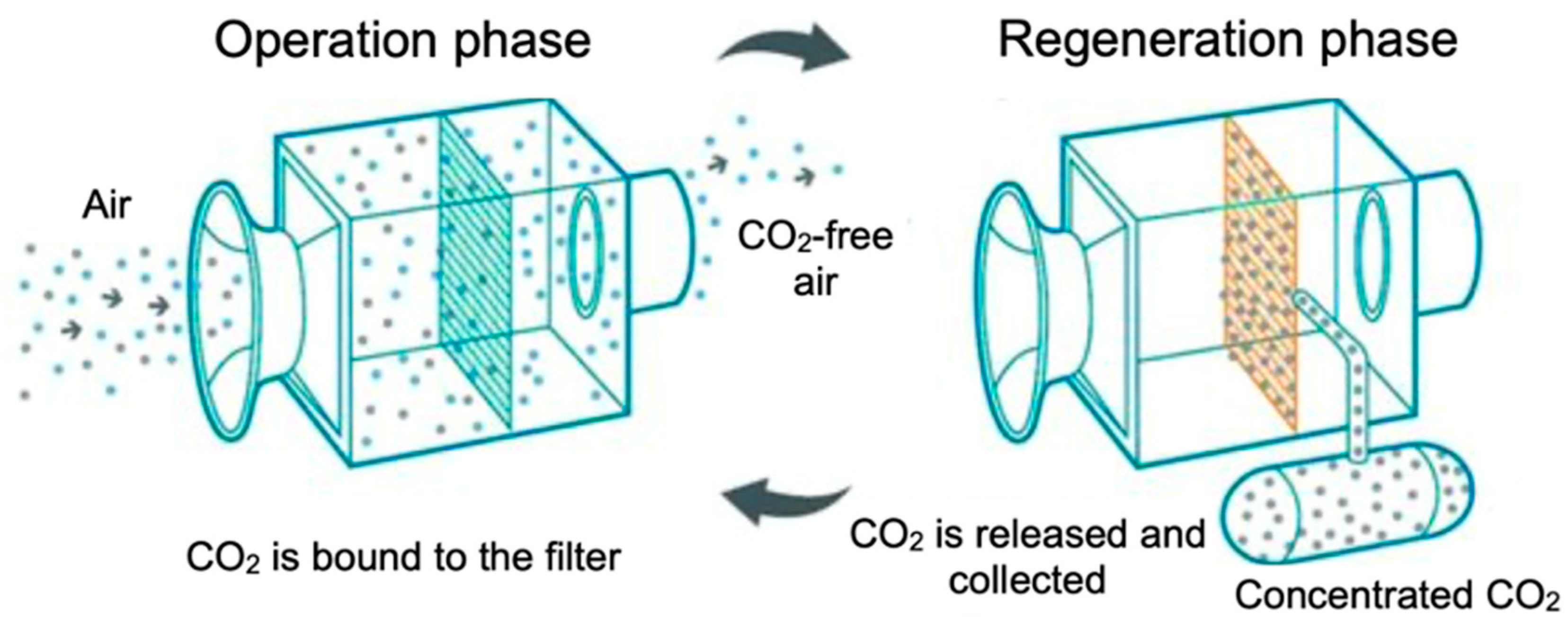
5.1. Fundamental Principle of S-DAC

The core principle of S-DAC technology involves using solid sorbents to capture CO2 from ambient air at room temperature and atmospheric pressure. Subsequently, CO2 is released from the sorbents under low pressure and moderate temperatures (80–100 °C) through a temperature-vacuum swing process. The process flow of this technology is illustrated in Figure 5.
In the current industrial application of S-DAC, the primary solid sorbents utilized are alkaline-functionalized sorbents [92], which are materials with alkaline functional groups such as amine groups [93], hydroxyl groups [93], quaternary ammonium groups [94], and piperidine groups [95]. The primary principle of these sorbents for capturing CO2 is acid–base reaction, supported by their high surface areas and porous structures, which enhance their CO2 adsorption capacities. Particularly, amine-based sorbents, where amine compounds (RNH2) are bonded to filter materials composed of dry porous granulates, are widely employed in S-DAC [24]. The high chemical reactivity, thermodynamic properties, and long-term stability of amine groups under ultralow CO2 concentration conditions make them particularly effective for capturing CO2 molecules [24]. These sorbents fix CO2 at ambient temperatures and, upon heating to the temperature range of 80–100 °C, the increased thermal energy facilitates the release of CO2 from the sorbents. Filter materials support and maintain the solid sorbents, and their porous structure allows air to pass through for adsorption. In S-DAC plants, fans draw air into collectors, where amine-based solid sorbents bind CO2, forming carbamate compounds through amination reactions. The reaction products depend on the presence of water in the system. In the absence of water, the products include ammonium carbamate ions and paired carbamic acid [30]. In the presence of water, the products include ammonium bicarbonate and water-stabilized carbamic acid [30]. This process fixes CO2, concentrating it on the filter, while CO2-free air is expelled from the collector. Once the solid sorbent is saturated with CO2, the adsorption process ends, and the collector is sealed and heated to desorb CO2. During this desorption process, the solid sorbent regenerates and regains its adsorption capacity, while pure CO2 gas is released. This cyclic process of adsorption and desorption enables the continuous capture of CO2 from the air and the release of pure CO2.

5.2. Advantages and Disadvantages of S-DAC

The current industrial-scale S-DAC technology offers advantages such as low energy consumption, low operating costs, and suitability for a wide range of scales. Specifically, compared to L-DAC, which may require temperatures as high as 900 °C for desorption, solid sorbents typically only need temperatures in the range of 80–100 °C, resulting in lower energy consumption and operating costs. Additionally, S-DAC technology operates in a small-scale modular mode, allowing scalability based on the needs of various application scenarios, from small laboratory setups to large industrial implementations [26]. This flexibility makes S-DAC a versatile solution for different CO2 capture applications. Furthermore, S-DAC can extract water from the air during the capture process, eliminating the need for an additional water supply.
The disadvantages of current S-DAC facilities primarily include high construction costs and the sustainability of sorbents. S-DAC relies on batch operations, requiring multiple units to be operated in parallel, resulting in larger, more complex plant structures and increased construction costs [26]. Additionally, the regeneration step in S-DAC necessitates periodic sealing of the entire structure from ambient air, along with cycling temperature, pressure-vacuum conditions, or humidity. These specific construction requirements further increase costs. Additionally, the solid sorbents are required to withstand prolonged exposure to impure environments without experiencing premature degradation or failure in capturing CO2. This necessitates regular replacement of the sorbents, thereby further increasing the operational costs [26,41].

5.3. Technological Advancements of S-DAC

In recent years, the optimization of solid sorbent materials has emerged as a primary advancement in S-DAC technology, aimed at enhancing the efficiency of CO2 capture from ambient air. Current research endeavors primarily focus on two key areas: the optimization of amine-based sorbents, and the utilization of porous materials with microscale-to-macroscale pores or voids.

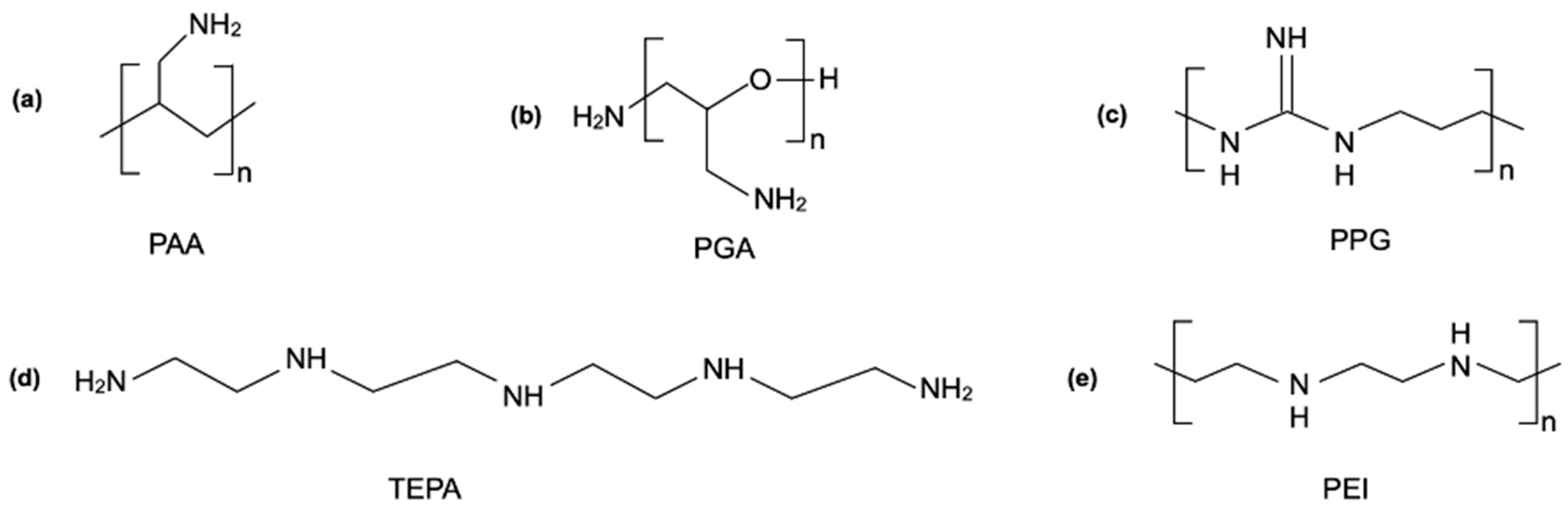
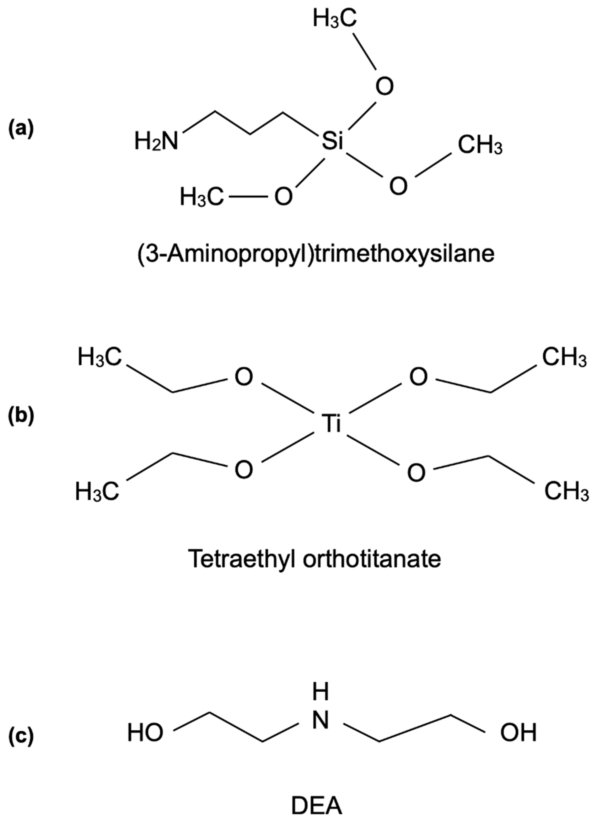
5.3.1. Advances in Amine-Based Sorbents

Recent optimization studies on amine-based solid sorbents have primarily focused on enhancing their adsorption performance by tethering or immobilizing them onto other supporting materials to form amine-modified sorbents [96].
In determining suitable basic amines for S-DAC technology, Heydari-Gorji et al. [97] and Sayari et al. [96] conducted thorough investigations into various types of amine compounds featuring different amine groups and molecular structures, focusing on aspects such as CO2 uptake capacity and stability. Their research confirmed that primary, secondary, and tertiary monoamines all exhibit decomposition at specific temperatures, and the decrease in CO2 uptake was attributed to the formation of urea linkages at the expense of amine groups [96]. The chemical structures of the basic amines commonly used for DAC are depicted in Figure 6. Polyethyleneimine (PEI) is considered to be a more suitable amine-based sorbent due to its structure containing high-temperature-stable monoamines [98], compared to other polyamine materials such as poly(allylamine) (PAA) [99,100], poly(glycidyl amine) (PGA) [101], poly(propylene guanidine) (PPG) [102,103], and tetraethylenepentamine (TEPA) [104,105].
To further optimize the CO2 capture performance of PEI, recent studies have focused on PEI-modified sorbents, a typical class of amine-modified sorbents [106,107,108]. These studies involved chemically modifying the basic structure of PEI. Significant progress has been made in utilizing silica supports to form PEI-based aminosilica materials, also referred to as silica-polyethyleneimine materials. Choi et al. proposed modifying PEI with (3-aminopropyl)trimethoxysilane (Figure 7a) to form A-PEI/silica, and with tetraethyl orthotitanate (Figure 7b) to form T-PEI/silica. Their research confirmed that these modified PEI-based aminosilica sorbents exhibit enhanced adsorption kinetics, higher CO2 adsorption capacities, and greater thermal stability compared to the original PEI. This improvement was attributed to the increased density of amine groups, stronger chemical bonds and interactions, and enhanced surface area and porosity [98]. Sayari et al. proposed loading PEI onto PME (pore-expanded MCM-41e), a silica support with internal surfaces fully covered by a uniform layer of readily accessible long alkyl chains from cetyltrimethylammonium (CTMA+) cations [109]. This PEI/PME material benefits from PME’s larger pore volume and surface area. Furthermore, PME serves as an excellent support due to the enhanced dispersion of PEI within the surface layer, which increases the accessibility of amine groups and improves mass transport [109,110]. These properties result in significantly enhanced CO2 capture performance for this material. Miao et al. introduced and synthesized a novel material, DEA/PEI, through the incorporation of diethanolamine (DEA) into polyethyleneimine (PEI) [106], with the molecular structure of DEA depicted in Figure 7c. This new material fully utilizes the synergistic effect between DEA and PEI to enhance CO2 capture capacity [106]. Specifically, in addition to exhibiting properties of larger pore volume, DEA’s hydroxyl groups facilitate increased accessibility between CO2 and amines while stabilizing the carbamate anion through hydrogen bonding. Additionally, the incorporation of DEA reduces the viscosity of PEI, thereby mitigating PEI’s agglomeration. Furthermore, the appropriate addition of DEA to PEI significantly extends the adsorption period, with a high adsorption rate, leading to enhanced CO2 capacities and amine efficiency [106]. The optimization of this DEA/PEI “mixed amine” system provides practical support for S-DAC applications.

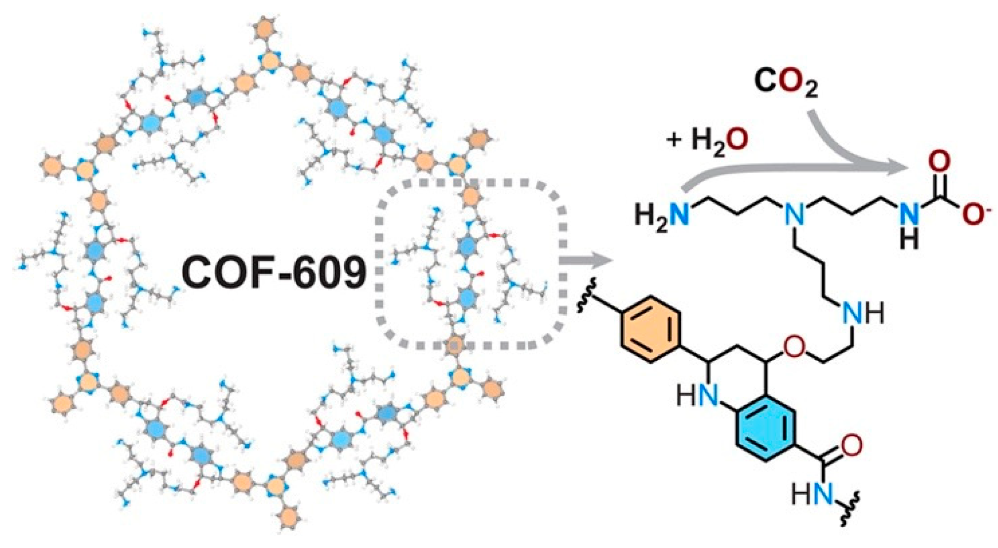
5.3.2. Advances in Porous Material Sorbents

The significant advantages of using porous materials for CO2 capture include their cleanliness, reversibility, and low energy demand [40]. Typically, these materials rely mainly on physisorption, primarily governed by van der Waals forces, although chemisorption may occasionally contribute to CO2 capture and separation. A wide range of porous materials have been studied for their potential application in S-DAC.
Some porous materials utilize their inherent pore structures for CO2 capture, exemplified by activated carbon (AC) [111,112,113], carbon-based materials (CBMs) [111,114,115], zeolites [111,116,117,118], boron nitride (BN) nanomaterials [119,120,121], and porous silica materials [122,123]. Chue et al. discussed the adsorption mechanisms and performance of AC, carbon molecular sieves (CMSs), and zeolites for CO2 capture [111]. AC primarily adsorbs CO2 onto its porous surface due to its high selectivity for CO2. CMSs, derived from CBMs, selectively adsorb CO2 based on pore size and polarity. Zeolites, which are aluminosilicate minerals, capture CO2 due to their adsorption capacities and higher selectivity for CO2 over N2. Abd et al. conducted a comprehensive review of recent advancements in ACs sourced from various origins for CO2 capture, emphasizing that surface modifications of these ACs can further enhance their adsorption performance [124]. Zaker et al. extensively explored CBMs as suitable candidates for CO2 capture, attributed to their cost efficiency, easy regeneration, and robust adsorption capacities for significant amounts of CO2 [125]. They provided detailed insights into the production, modification, and performance of CBMs, with a mechanism of CO2 capture by CBMs depicted in Figure 8a. Kumar et al. conducted a comprehensive analysis of the advancements and future prospects of zeolites as sorbents for CO2 capture, highlighting the significant potential of zeolites in this regard [116]. Their high porosity, ultra-small pores, structural diversity, stability, recyclability, and chemical reactivity contribute to their efficacy. A schematic illustration depicting CO2 capture by zeolites is presented in Figure 8b. Sun et al. demonstrated that porous BN nanomaterials, including BN nanosheets, nanotubes, and nanofibers, can achieve CO2 capture and release by simply controlling the charges carried by BN nanomaterials [119]. The schematic illustration of CO2 capture by BN nanomaterials is depicted in Figure 8c. Subsequently, Liang et al. proposed the utilization of Cu-loaded BN nanofibers, which exhibit significantly enhanced CO2 adsorption capacity and high recyclability for repeated uses compared to BN nanofibers [120]. This enhancement can be attributed to Cu’s ability to modulate electron transfer between porous BN and CO2, as illustrated in Figure 8d. Porous silica materials, characterized by highly ordered pore structures, high surface area, high pore volume, tunable pore size, and good thermal and mechanical stability, are also regarded as suitable candidates for CO2 capture. Amaraweera et al. conducted a comprehensive review of CO2 capture using porous silica materials, detailing various synthesis protocols for different types of mesoporous silica with diverse pore geometries, as well as other significant applications of these porous silica materials beyond CO2 capture [122].
In addition to the aforementioned materials with inherent porous structures, there has been a recent increase in the synthesis of materials specifically designed to have porous structures. These include metal–organic frameworks (MOFs) [126,127,128], covalent organic frameworks (COFs) [40,129,130], porous organic polymers (POPs) [131], porous aromatic frameworks (PAFs) [132,133], and polymers of intrinsic microporosity (PIMs) [134,135]. These materials share common characteristics, such as high porosity, high surface area, and structural tunability, making them promising solid sorbents for DAC applications.
MOFs are a class of hybrid porous materials, formed by tuning the type and arrangement of organic ligands and metal centers to create optimized pore structures and surface properties [126], as illustrated in Figure 9a. Ghanbari et al. conducted a comprehensive analysis of MOFs suitable for CO2 capture, detailing the mechanisms of CO2 selectivity over other gases, the preparation and synthesis methods of MOFs, and strategies to enhance CO2 adsorption on MOFs [126]. MOFs leverage their robust 3D permanent porous structure, extraordinary surface area, surface functionality, and modular nature to achieve CO2 separation and capture. The process of separating CO2 from air using MOFs is depicted in Figure 9b. When air passes through MOFs, several effects may contribute to the CO2 capture process. Among these, the molecular sieving effect is significant, wherein molecules with kinetic diameters matching the pore sizes of MOFs exhibit the highest affinity for the materials. CO2, with a kinetic diameter of 3.3 Å, aligns with the pore diameter of MOFs, enhancing its likelihood of capture within the pores compared to nitrogen [126,127]. Furthermore, the kinetic or thermodynamic equilibrium effect [128] is also significant. This effect arises from CO2’s large quadrupole moment, which, in contrast to the nonpolar nature of N2 molecules, enables the selective adsorption of CO2 by MOFs [126,128]. Furthermore, the presence of functional groups in the framework, such as polar groups [136,137], π-electrons [138], and coordinatively unsaturated metal sites [139,140], further enhances the interaction with CO2, promoting greater adsorption over other gas components [126].
COFs are porous materials composed of organic units connected by covalent bonds, characterized by highly ordered crystalline structures with adjustable pore size and morphology, high surface areas, and low density [141]. They are considered to be suitable candidates for CO2 capture as well as other applications [129,141,142,143,144], such as proton-conducting electrolytes, catalysis, and drug delivery. Li et al. conducted a review on COFs for CO2 capture, focusing on fabricating COFs to enhance CO2 capture efficiency [40]. They emphasized the vital role of COFs’ affinity for CO2, particularly under low-CO2-concentration conditions in DAC. Therefore, introducing CO2 affinity units such as -OH, -COOH, and -NH2 into COFs’ pores, either through covalent incorporation or physical loading, is an effective approach to increase CO2 uptake capacities [40,145]. Notably, Lyu et al. pioneered the covalent incorporation of amines into COFs [130]. In their study, they synthesized a novel material named COF-609, featuring a base-stable tetrahydroquinoline linkage covalently bonded to tris(3-aminopropyl)amine, the chemical structure and CO2 capture mechanism of which are depicted in Figure 10. This optimized material not only offers sufficient pore space to increase the contact area with CO2 but also enhances polarity and introduces a secondary amine into the structure, enabling strong chemisorption of CO2. This material achieves a 1360-fold increase in uptake capacity compared to the original framework for CO2 capture from dry air [130].
POPs, as amorphous porous materials, may not have the ideal structural crystallinity of MOFs and COFs; however, their simplicity of synthesis and low cost make them attractive candidates for large-scale, economical production as solid CO2 sorbents [131]. By using suitable functionalized precursors, the desired functionalities of POPs can be easily adjusted [146]. Different synthesis strategies allow for the incorporation of building blocks such as molecular cages and macrocycles, enabling diverse structures of POPs for complex gas separation tasks [147,148]. Additionally, POPs can act as hosts or directly as heterogeneous catalysts, achieving CO2 capture and conversion simultaneously [131]. Recent studies indicate that incorporating dispersed metal ion catalytic sites, single-atom catalysts (SACs), or nanoparticles such as Al, Zn, Co, Pd, Ir, Ru, and Ni into POPs, forming metal-containing POPs, can further enhance the functionality of heteroatoms within POPs [131,149]. This effectively creates stable, high-affinity binding sites and catalytic sites for CO2, thereby improving the CO2 adsorption and conversion performance of POPs. Song et al. provided profound and comprehensive insights into the significant impacts of different POPs’ structures and properties on CO2 capture, separation, and conversion processes [131]. The schematic illustration of the design principles of POPs for CO2 capture and separation, along with the subsequent conversion of CO2 into value-added products, is shown in Figure 11.
PAFs are high-surface-area materials with tunable chemical functionality, robust structural rigidity, and strong stability, making them highly suitable for applications in gas adsorption and separation, catalysis, and biochemistry. Their extensive benzene ring structures, formed through coupling reactions that create strong carbon–carbon covalent bonds, ensure a stable framework that is resistant to harsh chemical treatments [132]. The schematic illustration of their structure and applications is shown in Figure 12. The specific chemical functionalities of PAFs can be tuned both by the intrinsic properties of the building units and by the pillars formed through coupling reactions [132]. The aromatic groups within PAFs provide physical adsorption sites for CO2 [132,150]. Recent studies have demonstrated that adding polar functional groups, such as dihydrofuran, amine, methoxyl, and hydrogen, to PAFs can enhance their selectivity for CO2 in mixed gases [132,133]. Additionally, the electrostatic interactions between CO2 and PAFs are significant factors influencing CO2 capture performance [132,133,151]. Tian and Zhu conducted an in-depth analysis of the design principles and specific synthesis processes for PAFs in achieving various functions, emphasizing the importance of considering the properties of core building units and different coupling reactions [132].
PIMs share some similarities with other aforementioned porous materials, such as high pore volume, making them suitable for CO2 capture and separation. However, unlike the aforementioned materials, the pores in PIMs result from their contorted molecular structures, which inherently contain micropores due to intra-chain and inter-chain rigidities [135]. These micropores or ultra-micropores enhance the gas permeability of PIMs by fully utilizing the solution diffusion and convective diffusion mechanisms, making them highly efficient for CO2 capture and separation [135,152]. The CO2 adsorption performance of PIMs is affected by factors such as physical aging and plasticization [135]. Therefore, recent research on PIMs has focused on addressing these issues to prevent pore space reduction and decreased capture efficiency during usage. Shamsabadi et al. conducted a detailed evaluation of several newly developed PIMs and their CO2 separation performance, identifying potential PIMs suitable for industrial-scale separation of CO2/N2 and CO2/CH4 gas mixtures [135]. Yu et al. designed and synthesized an improved PIM, known as cyclohexyl-fused spirobiindane-based PIM (CCS-PIM), which exhibits a high specific surface area and excellent CO2-selective adsorption capacity [134,153]. The molecular structure of CCS-PIM is shown in Figure 13. This CCS-PIM features a six-membered ring-locking structure within the polymer backbone, resulting in a non-distorted chain structure with well-regulated micropore spaces. The precisely tuned pore size not only contributes to a highly rigid structure but also significantly enhances the molecular sieving effect, leading to outstanding gas separation performance [134].

6. Emerging DAC Technologies

In addition to the aforementioned established technologies, to address the growing urgency for more efficient and scalable solutions for DAC, some emerging technologies, including electro-swing adsorption (ESA), moisture-swing adsorption (MSA), and membrane-based separation (m-DAC), have been studied as promising alternatives.

6.1. Electro-Swing Adsorption (ESA)

ESA is a method that separates CO2 from high-concentration sources and the air by altering the charge to achieve capture and release of CO2 [154]. Specifically, CO2 is adsorbed when the solid electrode is negatively charged and released when the electrode is positively charged. The notable advantages of this CO2 separation method include several key aspects. Firstly, it allows for flexible adjustment and efficient operation by enabling the stacking and expansion of electrochemical cells according to the required capacity within a limited space. Secondly, the adsorption and release processes only require charge control, simplifying the operation and reducing the energy consumption associated with the regeneration of liquid solvents and solid sorbents. Additionally, this method simplifies the system’s complexity by eliminating the need for additional equipment, thereby reducing maintenance and operational costs in terms of time, labor, and economics. These advantages highlight the significant potential of ESA in carbon capture technology, making it highly efficient and adaptable to various scales and conditions of carbon capture requirements.
To enable ESA for the capture and release of CO2, electrochemical cells or electrode materials are required to facilitate the electrochemical processes [154]. Studies have shown that compounds such as quinones [154,155], 4,4′-bipyridine [154,156], and thiolates [157,158] can serve as carrier molecules for CO2 during the electrochemical processes of adsorption and desorption. Quinones, in particular, exhibit superior electrochemical performance and have the potential to achieve near 100% purity of released CO2 [154], making them the preferred material for CO2 oxidation–reduction activity carriers in electrochemically mediated separation processes [154,155].
Voskian and Hatton designed a faradaic electrochemical cell utilizing quinones for CO2 capture and release [154]. The structure and operational principle of this cell are illustrated in Figure 14. The cell comprises two cathode electrode substrates coated with polyanthraquinone–CNT (PAQ-CNT), a composite material of quinone and carbon nanotubes (Q–CNT), which serves as a mediator for the adsorption and desorption of CO2 molecules via its redox reactions. An anode electrode substrate coated with polyvinylferrocene–CNT (PVFc-CNT), a composite of ferrocene and CNTs (Fc–CNT), is positioned between the two cathode substrates to provide electrons for the quinone’s redox reactions. Separator membranes are placed between the cathode and anode substrates to prevent direct electron transfer and allow ion passage. The use of CNT composite materials, with their high surface area and conductivity, facilitates effective ion transfer through the electrolyte during electrode activation and deactivation, allowing for CO2 diffusion during the capture process. During CO2 capture with this cell, a reduction potential is applied to the outer cathode electrode, causing the PAQ-CNT composite to absorb electrons and undergo a reduction reaction, leading to a carboxylation reaction between CO2 and quinone for CO2 capture. Subsequently, when an oxidation potential is applied to the outer cathode electrode, the PAQ-CNT releases electrons and undergoes an oxidation reaction, releasing the adsorbed CO2. The inner PVFc-CNT electrode serves as the electron source and sink for the quinone reduction and oxidation [154]. These electrochemical cells can be stacked to form a contactor with parallel passages in a flow device, thereby providing a larger surface area for contact with CO2 in the feed stream, enhancing the efficiency of CO2 capture in the ESA process [154]. This solid-state faradaic ESA system has demonstrated exceptional performance in CO2 capture. Its compact and flexible architecture allows for stacking to create a suitable contactor with a large surface area for efficient CO2 capture. The system exhibits effective CO2 capture capacity, maintaining up to 10% CO2 even at concentrations as low as 0.6%. It achieves a high faradaic efficiency of over 90% and low energy consumption ranging from 40 to 90 kJ per mole of CO2 captured. Additionally, the electrochemical cells show great durability, with less than 30% capacity loss after 7000 cycles [154]. These promising results underscore the significant potential of this ESA system for industrial applications.
The current status of this technology is in the laboratory-scale testing phase, with ongoing research focusing on enhancing the performance characteristics of the redox materials [159], such as capacity [160], kinetics [159,160], and chemical and physical stability [148]. Simultaneously, relevant cost analyses are being conducted to advance potential large-scale deployment in the future [160].

6.2. Moisture-Swing Adsorption (MSA)

With its advantage of reduced energy consumption, MSA is considered to be a method capable of replacing the current temperature-swing process in S-DAC [161,162,163]. Specifically, MSA involves adsorbing CO2 under dry conditions and desorbing it under humid conditions by altering the environmental water vapor pressure at low temperatures (45 °C). Compared to the temperature-swing method used in current S-DAC systems, MSA requires humidity control and lower temperature conditions, making it more operationally convenient while reducing the energy consumption associated with heating. Furthermore, its low temperature requirement facilitates integration with other processes and energy systems, such as utilizing solar energy or waste heat to provide the energy needed for humidification [164].
The fundamental mechanism for CO2 adsorption and desorption in MSA is the change in the free energy of the chemical reaction between carbonate ions and water molecules. Specially, the decrease in the number of water molecules in sorbents leads to a decrease in the free energy change, thereby promoting the capture of CO2 [165]. The adsorbent used in MSA is moisture-sensitive, interacting with water to affect the energy states of carbonate, bicarbonate, and hydroxide ions through hydration and dehydration. As a result, the equilibrium between these ions is altered to achieve CO2 capture and release. The schematic diagram of MSA for CO2 capture and release, along with the potential moisture-driven sorbents, is shown in Figure 15.
Recent studies have proven that ion-exchange resins are ideal moisture-driven sorbents in MSA due to their excellent ion-exchange capacity, sensitivity to changes in ambient humidity, and low sorption heat for energy saving [165]. Shi et al. demonstrated through simulation [166] and experimental results [165] that ion-exchange resins can serve as moisture-driven CO2 sorbents by enabling CO2’s capture and release through the manipulation of water activity in the surroundings of the sorbent, leveraging the isolated carbonate ion hydration in these materials. Specifically, low humidity causes the functional groups of the ion-exchange resin to compete with water molecules, leading to water dissociation on the surface and the formation of bicarbonate ions. This process facilitates direct CO2 capture by adsorbing CO2 onto hydroxide ions. Conversely, increasing the humidity results in more water molecules on the sorbent’s surface, causing bicarbonate ions to revert to carbonate and release CO2. The authors experimentally demonstrated that quaternary ammonium ions or functional groups provide a fixed positive charge capable of carrying CO32− ions. Using polystyrene resin with quaternary ammonium ions, they observed significant changes in CO2 concentration due to its capture and release under varying humidity conditions [165]. Subsequently, based on the properties of quaternary ammonium ions, some studies have focused on further optimizing ion-exchange resins as moisture-driven sorbents [161,167]. Wang et al. proposed an advanced method for improving the properties of ion-exchange resins by grafting quaternary ammonium functional groups onto high-surface-area mesoporous polymers, resulting in a sorbent with ultra-high kinetics [167]. This method effectively utilizes the uniform cylindrical pore structure to efficiently attach quaternary ammonium functional groups to active substitution sites. This optimized structure not only enhances the efficiency of the functional groups but also leverages the capillary action of the pore structure [167,168,169,170,171], further enhancing the CO2 capture capacity. Building on the properties of quaternary ammonium ions, Biery et al. further optimized the mechanical performance of sorbents containing quaternary ammonium ions. Specifically, they designed and synthesized sulfone-based multiblock copolymers containing ammonium functionalities [161]. This synthesis leverages the combined properties of polysulfones, which offer excellent strength and thermal stability, and quaternary ammonium polymers, which provide superior ion-exchange properties. A series of multiblock copolymers containing both polydiallyldimethylammonium (PDADMA) and polysulfone (PSf) blocks were synthesized, where the PDADMA blocks directly capture CO2 and the PSf blocks provide mechanical integrity. These optimizations of moisture-driven sorbents enhance the capture efficiency and durability during application, promoting the broader practical use of moisture-driven DAC.

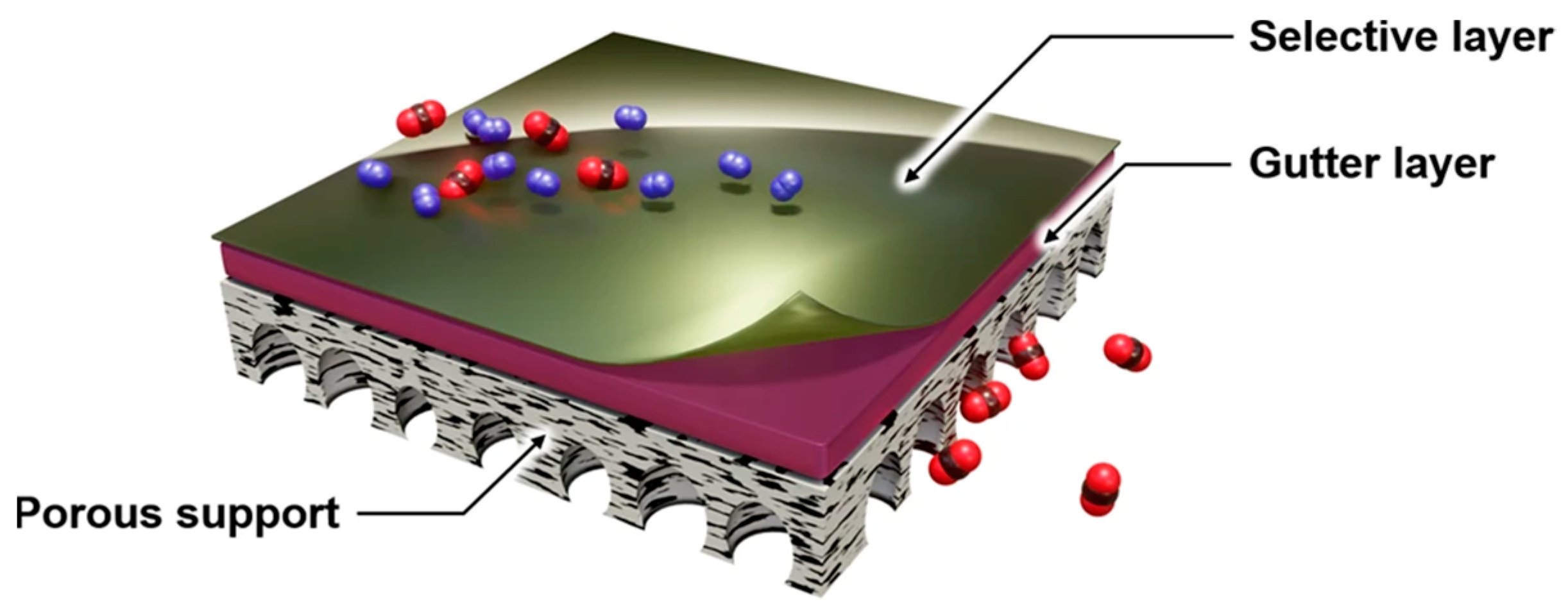
6.3. Membrane-Based Separation (m-DAC)

Applying membrane separation technology to DAC is known as m-DAC [33]. The core principle of membrane separation technology lies in utilizing specific permeable membranes to control the transfer of substances across the membrane, thus achieving the separation and capture of target substances. Therefore, using membranes with high CO2 permeability, m-DAC allows CO2 to pass through while retaining other gases on the opposite side, effectively separating CO2 from the air.
When compared to other DAC technologies, m-DAC stands out for its low energy consumption, making it a potentially viable energy-saving solution [40]. Additionally, it offers straightforward and stable operation, along with a small footprint [32]. However, a current challenge limiting the widespread adoption of this technology is the low flux associated with membrane separation due to the low partial pressure of CO2 in air [172,173], resulting in poor economic viability. Addressing this challenge, recent efforts in optimizing m-DAC technology have primarily focused on the development of membrane materials with high CO2 permeability and selectivity. Significant progress has been achieved in advancing membrane materials.
Thin-film composite or ultrathin-film composite (TFC) membranes, characterized by nanometer-scale thicknesses, are recognized ideal for m-DAC [174]. The structural composition of TFC membranes is depicted in Figure 16, comprising a selective layer, a gutter layer (alternatively referred to as the intermediate layer), and a porous support. Building on the fundamental principle that the ethylene oxide (EO) unit facilitates favorable interactions with CO2 over light gases for separation [175], Fu et al. proposed a class of TFC membranes containing high-molecular-weight amorphous polyethylene oxide (PEO) with high EO moieties to enhance CO2 permeability and flux [172]. Specifically, this optimized membrane system comprises a polymer membrane matrix with a selective layer containing PEO and a gutter layer composed of polydimethylsiloxane (PDMS). The incorporation of multiple PEO blocks interspaced with a specially designed terephthalic spacer into the base polymer membrane matrix significantly enhances the CO2 separation ability without inducing crystallinity [172]. Meanwhile, the PDMS gutter layer serves as a protective coating to maintain membrane surface smoothness and efficiency by preventing penetration of the diluted polymer solution into the porous structure, ensuring smooth gas separation [172,176]. Moreover, researchers have sought to enhance gas permeance by reducing membrane thickness, given the general inverse relationship between gas flux and membrane thickness. Yoo et al. proposed using the Teflon-based material AF2400 instead of PDMS as the gutter layer, with a thickness of only 75 nm, coupled with a 70 nm selective layer, forming an ultrathin membrane [174]. This optimization reduces membrane thickness and significantly enhances CO2 permeance sixfold compared to membranes with PDMS as the gutter layer, thus greatly improving the CO2 separation efficiency. To further reduce membrane thickness, Fujikawa et al. proposed utilizing the inherent gas permeance property of PDMS due to its dynamic polymer chain nature, enabling the direct production of free-standing PDMS nanomembranes for CO2 separation [177]. By controlling the spinning speed and PDMS concentration during the spin-coating process, they achieved a thickness of 34 nm. The experimental results demonstrated a fourfold increase in CO2 permeance from 10,000 GPU to 40,000 GPU when reducing the PDMS membrane thickness from over 100 nm to 34 nm. These optimizations result in TFC membranes with higher CO2 permeance and selectivity, reducing the gas permeance resistance and making CO2 gas capture from diluted emission sources more feasible.
Mixed-matrix membranes (MMMs) are another promising candidate for m-DAC. These membranes incorporate various porous fillers, such as carbon molecular sieves [178], zeolites [179,180], MOFs [181], and COFs [182,183], into a polymer matrix to enhance CO2 separation and enable repeated use. MMMs combine the high adsorption capacity of porous fillers with the mechanical strength of polymers. Typically, MMMs can be fabricated using techniques similar to conventional polymeric membranes [184,185], with fillers ranging from spherical with a low aspect ratio to thin platelet-type with a very high aspect ratio [186]. Research on MOF-based and COF-based MMMs has been increasing due to their advantages as porous materials with tunable pore sizes and properties [181,182,183,185].
MOF-based MMMs improve CO2 separation efficiency by altering the microenvironment of the MOF and polymer matrix [187], enhancing their adhesion [188], and rationally designing them for desired interfacial properties [188]. Additionally, research suggests that the mechanical properties of MOF-based MMMs, including thermomechanical, stress–strain, and viscoelastic properties, can be enhanced through interactions between the MOF and the polymer matrix [189,190]. COF-based MMMs show potential for m-DAC due to the thermal and chemical stability of covalently bonded COFs as ideal fillers. While direct use of pristine COFs as fillers in MMMs is feasible [191,192], studies have shown that modifying COFs before use can further improve CO2 separation performance [193,194]. Liu et al. proposed a multi-function integration strategy to enhance COF-based MMMs’ CO2 separation performance [194]. They optimized the COF fillers’ properties by considering their entire morphological structure, aperture adjustment, and channel decoration. The inner and outer surfaces of the improved COF fillers were then modified with polyethylene glycol monomethyl ether (PEG) to form hollow microspheres, reducing the mass transport resistance. Finally, these modified COF fillers were incorporated into a commercial Pebax polymer matrix to create the designed COF-based MMM for CO2 capture. This COF-based MMM utilizes PEG functionalization to modify the COF inter-surface by providing ethylene oxide groups, which have an affinity for quadrupolar CO2 and decrease the pore size to enhance CO2’s solubility selectivity and diffusion selectivity. Meanwhile, PEG chains on COFs’ outer surface improve compatibility between the COF fillers and the Pebax matrix. As a result, this COF-based MMM achieves superior CO2 separation performance.
It is noteworthy that the evaluation of different membranes for m-DAC can be effectively conducted using advanced simulation software and computational modeling tools [195]. Platforms such as ASPEN HYSYS [196], Aspen Plus V11 flowsheeting software [33], and COMSOL Multiphysics [195] are invaluable for predicting and optimizing the performance of various membrane materials, providing a cost-efficient means to assess and enhance their performance.

7. Comparison of DAC Technologies

In the preceding sections, L-DAC, S-DAC, and emerging DAC technologies have been comprehensively introduced. The principles, commonly employed materials, advantages, and disadvantages of these technologies are summarized in Table 3 for a more intuitive comparison.
L-DAC and S-DAC, as extensively industrialized technologies, are notable for their technical maturity. However, their drawbacks cannot be overlooked. L-DAC suffers from high energy consumption and requires corrosion-resistant equipment. S-DAC’s challenges include complex plant structures due to batch operations and specialized construction for cycling temperature and pressure conditions, resulting in high investment costs. These significant drawbacks may limit their broader global adoption.
Emerging DAC technologies, including ESA, MSA, and m-DAC, show considerable promise, albeit they are still in the research and development phase, with limited large-scale applications. These technologies boast significant advantages, particularly in their low energy consumption for CO2 capture and separation. Their operational simplicity positions them as highly viable for future DAC applications. Notably, innovative polymer materials used as moisture-sensitive sorbents in MSA technology, along with their synthesis routes, have been submitted for patent applications [197,198]. The Mechanical TreesTM based on MSA technology utilizing these sorbents are currently undergoing commercialization through a collaboration between Arizona State University and Carbon Collect.

8. Practical Applications of DAC

The application status of DAC technology serves to inform global industries about its practical implementation. According to the IEA, as of 2023, there are 27 operational DAC plants globally, mainly situated in North America, Europe, Japan, and the Middle East. These facilities collectively capture nearly 0.01 Mt CO2 annually. Furthermore, plans are underway for the development of at least 130 additional DAC facilities, at various stages of implementation [199]. Globally, the leading companies focused on DAC include North American companies such as Carbon Engineering, Global Thermostat, CarbonCapture, and Baker Hughes. European companies in this field include Climeworks, Antecy, Skytree, Carbon Collect, and Hydrocell [30].
Currently, North America hosts several notable DAC plants, exemplifying the region’s engagement with DAC technology [26]. The basic information of typical representative DAC facilities in North America is shown in Table 4.
Notably, the United States stands out for its robust policy support. With the introduction of the Inflation Reduction Act (IRA) in 2022, the 45Q tax credit for CO2 capture was increased to USD 180 per ton stored. This policy support, coupled with a capture threshold as low as 1000 tons of CO2 annually, positions the United States as a global leader in DAC applications. The current notable projects under development in the United States include STRATOS in Texas, the Oxy-CE Kleberg County project, the HIF eFuels Matagorda County project, the Bison project, and the Adams County project [199].
In the United States, DAC plants widely adopt the mature and well-developed L-DAC technology using alkaline solutions, as discussed in Section 4. This technology, developed and improved by Carbon Engineering (CE), a Canadian-based clean energy company, utilizes KOH solution as the liquid solvent. It features a contactor with a cross-flow pattern for air and the alkaline solution, ensuring efficient contact for the reaction. Aspen Plus simulation is employed to determine the operational parameters related to energy and material balances [41]. Typical industrial-scale applications of this technology include the STRAROS DAC1 and the Oxy-CE Kleberg County project, both located in Texas, USA. The STRAROS DAC1, which employs CE’s L-DAC technology, was constructed by Oxy Low Carbon Ventures (OLCV) through its subsidiary 1PointFive (Houston, TX, USA). This facility, using a scalable setup, aims to capture 1.0 Mt CO2/year and, ultimately, sends compressed pure CO2 to geological storage sites for permanent sequestration. Expected to commence operation in 2024, it is currently the world’s largest DAC facility [199,200]. The Oxy-CE Kleberg County project, the second DAC facility site in the United States, employs the same design as STRAROS DAC1, with CE’s L-DAC technology [201]. Located in the Gulf Coast region, the DAC plant leverages ideal porous formations for geological storage, ensuring safe and verifiable CO2 removal and storage. The project adopts an innovative deployment approach to standardize factory design, accelerate construction, and establish a supplier supply chain for local partners, facilitating rapid progress.
The HIF eFuels Matagorda County project, a collaboration between Baker Hughes (BKR) (Houston, TX, USA) and HIF Globa (Houston, TX, USA), involves testing Baker Hughes’s Mosaic DAC technology pilot units in Matagorda County, Texas. This technology utilizes MOFs as the primary sorbent material and aims to accelerate DAC’s deployment at a commercial scale [202]. By leveraging the porous structure and adsorption capabilities of MOFs, the project implements a groundbreaking low-cost DAC initiative to accelerate CO2 capture. The captured CO2 is then combined with green hydrogen to produce 150,000 barrels of eFuels per day, contributing to the decarbonization of over 5 million vehicles in use.
Project Basin in Wyoming utilizes a low-cost modular DAC system developed by CarbonCapture Inc. (Los Angeles, CA, USA) to filter CO2 from the air [199]. The technology allows for scalability and integration with extensive renewable energy facilities like wind and solar power. Subsequently, Frontier Carbon Solutions (Dallas, TX, USA) collects this captured CO2 and injects it into deep saline aquifers using Class VI injection wells managed by the Wyoming Department of Environmental Quality, as per EPA regulations [203]. The Adams County project by Global Thermostat (Denver, CO, USA) features one of the world’s largest DAC machines. This project has been capturing over 1000 tonnes of CO2 annually since late 2022, using S-DAC [203].
Furthermore, the Carbon Engineering Innovation Center, situated in Squamish, British Columbia, Canada, stands as the world’s largest facility dedicated to research and development in DAC, established by CE since 2015 [41]. It serves as an advanced research platform where CE’s DAC technologies undergo testing before implementation in practical applications, including the aforementioned STRAROS DAC1 and Oxy-CE Kleberg County project.
In Europe, several countries have established DAC plants, including Switzerland, Iceland, the United Kingdom, Norway, Italy, Germany, and the Netherlands. Among these, Germany and the Netherlands host DAC plants of modest scale, capturing below 50 t CO2/year. DAC plants with larger CO2 capture capacities are predominantly found in the United Kingdom, Norway, and Iceland. The basic information of these typical DAC plants is detailed in Table 5.
The DAC facility located in the northeastern part of Scotland, UK, is a collaborative effort between Storegga, a UK-based company, and Carbon Engineering. Expected to start operations in 2026, this DAC plant will mark Europe’s inaugural large-scale DAC facility, integrating DAC technology with geological storage, with support from Scotland’s renewable energy and oil and gas industry expertise. It is expected to permanently remove between 500,000 and 1,000,000 tonnes of CO2 annually [205].
The Kollsnes DAC project, located in Norway, is a collaborative effort involving three companies: Carbon Removal, Carbon Engineering, and Oxy Low Carbon Ventures [206]. This DAC project utilizes L-DAC technology and is expected to capture between 500,000 and 1,000,000 tonnes of CO2 from the atmosphere annually. Leveraging policy support from the Norwegian government and mature technologies from the reliable renewable energy, oil, and natural gas industries, significant amounts of CO2 will be permanently stored in subsea geological storage sites through this project.
The DAC plants in Switzerland and Iceland primarily employ S-DAC technology with filters containing solid sorbent materials, as described in Section 5. This technology is designed and developed by Climeworks, a Swiss company specializing in direct air capture and storage (DAC+S). These S-DAC facilities exclusively use renewable energy, waste-to-energy, or other waste heat sources, significantly minimizing their carbon footprint and enhancing the sustainability and efficiency of their energy usage. Typical DAC plants employing S-DAC technology include the Capricorn plant in Switzerland and the Artic Fox, Orca, and Mammoth plants in Iceland. The Capricorn project, situated near the town of Hinwil, Switzerland, started operations in 2017, marking Climeworks’ first industrial-scale DAC plant [207]. It consists of 18 CO2 collectors and utilizes waste heat from a local waste incineration plant to power the capture process. This facility is capable of capturing hundreds of tons of CO2 annually. A portion of the CO2 captured from the air is delivered to nearby greenhouses for vegetable fertilization, while another portion, after liquefaction, is transported to the beverage industry for utilization.
The three DAC projects in Iceland are all based in Hellisheidi, using renewable energy such as geothermal energy from local geothermal power plants to power the DAC plants. Among these projects, Arctic Fox, which launched in 2017, is the first DAC facility built by Climeworks in Iceland [208]. One CO2 collector was established in this project, with the ability to capture 50 tons of CO2 annually. The captured CO2 is mixed with water using Carbfix’s technology and then pumped deep underground, where a natural mineralization reaction occurs between CO2 and basalt rocks, achieving permanent geological storage of CO2. After the successful operation of this project, Climeworks established another DAC plant named Orca in 2021 [209]. This project adopts an improved design and uses eight collectors, each with a collection capacity of 500 tons. The entire plant can capture up to 4000 tons of CO2 per year, making it the largest direct air capture and storage plant in the world. Starting in 2022, Climeworks began the construction of a DAC plant called “Mammoth”, which is expected to be completed and put into use in 2024 [210]. It is expected that, after the plant is put into use, it will be able to capture up to 36,000 tons of CO2 per year, which will constitute an important milestone in increasing the carbon removal capacity from thousands to tens of thousands of tons per year.
Despite the current global application of DAC technology being primarily small-scale, increasing emphasis on CO2 emissions worldwide is leading to greater funding for DAC research and implementation, which will accelerate its large-scale deployment. In 2021, the United States allocated USD 3.5 billion for DAC hubs and launched a DAC Prize program with USD 115 million for commercial and pre-commercial projects [26]. Similarly, new R&D funding in countries such as Australia, Canada, Japan, and the UK underscores the international recognition of the importance of developing and scaling up DAC technologies [26]. Additionally, regions with high renewable energy potential, including the Middle East, China, Europe, North Africa, and the United States, have been identified as some of the least-cost locations for DAC deployment [26]. The abundance of renewable energy in these regions will significantly reduce DAC costs, making them ideal for the large-scale implementation of DAC in the future.

9. Challenges and Future Directions

Compared to point sources of high-concentration CO2, such as refineries, power plants, or cement factories, the inherent dilution of CO2 in the atmosphere results in significantly lower concentrations. This characteristic necessitates denser deployment, larger operational scales, increased energy supply, and more effective but higher-cost materials for DAC facilities. Consequently, the cost of DAC significantly exceeds that of traditional capture techniques when capturing the same amount of CO2. Thus, the economic feasibility of DAC faces significant challenges, which are pivotal factors limiting its widespread application. To address these challenges, efforts can be directed towards optimizing energy supply, refining technologies and process designs, and strengthening financial support and incentive measures from governments and international organizations.
Currently, DAC plants primarily rely on natural gas as their primary energy source, with some utilizing waste heat from nearby incineration plants and geothermal energy. Transitioning towards greater utilization of low-cost renewable energy sources instead of natural gas could markedly decrease operational expenses for DAC facilities. Renewable sources like wind, solar (or photovoltaic), and geothermal energy stand out as particularly promising alternatives. Fasihi et al. conducted techno-economic analyses of DAC technologies and demonstrated that DAC plants powered by hybrid PV–wind–battery energy systems could position DAC facilities to compete on cost with traditional carbon capture methods used in CO2 point sources [163]. Further in-depth research focusing on cost analysis of low-carbon energy sources such as geothermal energy, solar power, nuclear power, electricity supply, and waste heat for DAC holds the promise of significantly reducing operational costs and promoting wider adoption of DAC plants.
In the advancement of technology and processes, experimental studies and on-site testing of DAC plants in different environments are crucial for the global application of DAC technology. One significant advantage of DAC technology lies in its flexibility in site selection, which should be fully utilized to achieve global net-zero carbon emissions. Based on the current operational status of DAC facilities worldwide, DAC plants can operate successfully in diverse environmental conditions, even in harsh environments like Iceland. However, some uncertainties still persist, particularly in extremely dry or humid climates, or in areas with severe air pollution, where the feasibility of DAC facilities’ operation remains undetermined. Extremely dry climatic conditions may further reduce the concentration of CO2 in the air, while humid conditions could affect the performance and durability of DAC equipment. Additionally, polluted air may contain other chemical substances that could interfere with or damage DAC facilities. To address these issues, future research can begin by using simulation software and conducting small-scale laboratory experiments under simulated environmental conditions to optimize airflow and relevant parameters after air enters the equipment. Subsequently, small-scale testing should be conducted in real environments, equipped with necessary monitoring devices to collect operational data and validate the laboratory findings. For highly polluted conditions, effective air filtration and pretreatment technologies could be integrated into DAC facilities to remove harmful substances that may affect DAC equipment’s performance, ensuring smooth CO2 capture operations.
The continuous investment in research and development and comprehensive policy support are crucial for the advancement of DAC technology. Sufficient government funding and investment, along with effective market mechanisms like an improved carbon trading market system, tax incentives, and subsides, as well as strong policy support, can incentivize relevant researchers and companies to actively improve process workflows, optimize equipment designs, reduce raw material costs, and conduct more on-site testing. Furthermore, given the global impact of climate change, international cooperation and coordination are particularly important. The sharing of technology and expertise facilitates the more effective and rapid deployment of DAC plants worldwide.
Furthermore, broader utilization of CO2 can significantly contribute to creating an ideal market and reducing costs for DAC. One important and typical application involves using CO2 captured by DAC technology for synthetic fuel production. Current research has achieved the synthesis of fuels by reacting CO2 captured by DAC with hydrogen [28,211,212]. In such studies, renewable energy sources such as wind and solar power are utilized to provide heat or electricity for electrolysis, facilitating sustainable hydrogen generation to react with CO2 for synthetic fuel production. Through this approach, various fuels, including methane, methanol, and diesel, can be produced [213]. These synthetic fuels find notable application prospects in the transportation sector, particularly in aviation, offering a viable solution for reducing emissions from conventional fossil fuels [26]. However, compared to fossil fuels, the current cost of synthesizing such fuels remains relatively high. Therefore, future research efforts will focus on reducing the synthesis costs of these fuels. Additionally, integrating appropriate electrochemical conversion processes to react CO2 captured by DAC with other raw materials to produce engineering polymers/resin precursors, specialty chemicals, and bulk chemicals will be a promising future research direction [2].
Additionally, it is worth noting that artificial intelligence (AI) methodologies have gained considerable attention in recent years for their ability to efficiently process and analyze complex data patterns and optimize system operations in CCUS and DAC [214,215]. AI, including related machine learning (ML) methods, has been studied and used for modeling, simulation, and optimization in carbon capture to accelerate the optimization of material selection and expedite the design of capture/utilization systems [216,217]. Future development of more accurate predictive models and optimization algorithms will further promote the broader application of AI technology in the CCUS and DAC fields, with its capacity for rapid analysis of large amounts of real-time data, resulting in higher carbon capture efficiency and lower costs.

10. Conclusions

DAC technology, with its capacity to directly capture low-concentration CO2 from the atmosphere without requiring connection to specific emission sources, presents a versatile and scalable solution for mitigating atmospheric CO2 emissions. It is recognized as a pivotal technology in attaining net-zero or negative emissions targets, thereby positioning DAC as a promising pathway for global carbon reduction initiatives and enabling broader carbon neutrality objectives worldwide.
L-DAC and S-DAC, as mature technologies, have been implemented on an industrial scale. Recent advancements in L-DAC have predominantly concentrated on enhancing engineering aspects in practical applications to ensure projects’ economic feasibility. This involves optimizing engineering costs while maximizing capture efficiency. Additionally, significant recent research progress has been achieved in exploring alternative solvents for L-DAC, beyond alkaline solutions. Progress in S-DAC has focused on enhancing the performance of amine-based sorbents and assessing porous materials with microscale-to-macroscale pores or voids as potential sorbents for industrial applications.
ESA, MSA, and m-DAC are emerging DAC technologies aimed at providing more efficient and scalable solutions for DAC. Although these new technologies are still in the research and development phase and have not yet been widely implemented, they possess several obvious advantages, such as lower energy consumption, simpler operation, and reduced maintenance and operational costs. These benefits will facilitate their broader application in the future, enabling more efficient atmospheric CO2 capture.
Currently, industrial-scale DAC plants operating in North America and Europe are performing well. The primary constraint on the broader deployment of DAC technology is its economic feasibility. Promoting DAC on a global scale can be achieved by optimizing energy supply, refining technologies and process designs, and strengthening financial support and incentives from governments and international organizations. Additionally, expanding the utilization of CO2, such as using CO2 captured by DAC for synthetic fuel production and the synthesis of other valuable chemical materials, will also help advance the adoption of DAC technology worldwide.

Author Contributions

G.L.: original draft writing, resources, and visualization; J.Y.: conceptualization, original draft writing, review, and editing. All authors have read and agreed to the published version of the manuscript.

Funding

This research received no external funding.

Institutional Review Board Statement

Not applicable.

Informed Consent Statement

Not applicable.

Data Availability Statement

Not applicable.

Acknowledgments

The authors are grateful to the Departments of Chemical Engineering and Petroleum Engineering at the University of Wyoming for their support.

Conflicts of Interest

The authors declare no competing interests.

References

  1. Baker, H.S.; Millar, R.J.; Karoly, D.J.; Beyerle, U.; Guillod, B.P.; Mitchell, D.; Shiogama, H.; Sparrow, S.; Woollings, T.; Allen, M.R. Higher CO2 Concentrations Increase Extreme Event Risk in a 1.5 °C World. Nat. Clim. Change 2018, 8, 604–608. [Google Scholar] [CrossRef]
  2. Yao, J.; Han, H.; Yang, Y.; Song, Y.; Li, G. A Review of Recent Progress of Carbon Capture, Utilization, and Storage (CCUS) in China. Appl. Sci. 2023, 13, 1169. [Google Scholar] [CrossRef]
  3. Storrs, K.; Lyhne, I.; Drustrup, R. A Comprehensive Framework for Feasibility of CCUS Deployment: A Meta-Review of Literature on Factors Impacting CCUS Deployment. Int. J. Greenh. Gas Control 2023, 125, 103878. [Google Scholar] [CrossRef]
  4. Han, J.; Li, J.; Tang, X.; Wang, L.; Yang, X.; Ge, Z.; Yuan, F. Coal-Fired Power Plant CCUS Project Comprehensive Benefit Evaluation and Forecasting Model Study. J. Clean. Prod. 2023, 385, 135657. [Google Scholar] [CrossRef]
  5. Ritchie, H. Sector by Sector: Where Do Global Greenhouse Gas Emissions Come From? OurWorldInData.org. Available online: https://ourworldindata.org/ghg-emissions-by-sector (accessed on 18 September 2020).
  6. Bai, X.; Yan, G.; Kong, S.; Yao, J.; Wen, P.; Li, G.; Li, J.; Zhang, J. Suppression of Anthracite Dust by a Composite of Oppositely-Charged Ionic Surfactants with Ultra-High Surface Activity: Theoretical Calculation and Experiments. Fuel 2023, 344, 128075. [Google Scholar] [CrossRef]
  7. Bai, X.; Yan, G.; Kong, S.; Yang, T.; Yao, J.; Wen, P.; Li, G. Study on the Mechanism of the Influence of Surfactant Alkyl Chain Length on the Wettability of Anthracite Dust Based on EDLVO Theory and Inverse Gas Chromatography. Fuel 2023, 353, 129187. [Google Scholar] [CrossRef]
  8. Yao, J.; Li, G.; Wu, J. Application of In-Situ Combustion for Heavy Oil Production in China: A Review. J. Oil Gas Petrochem. Sci. 2018, 1, 69–72. [Google Scholar] [CrossRef]
  9. Yao, J.; Song, Y. Dynamic Analysis Approach to Evaluate In-Situ Combustion Performance for Heavy Oil Production. J. Oil Gas Petrochem. Sci. 2019, 2, 42–47. [Google Scholar] [CrossRef]
  10. Ivanova, S.; Vesnina, A.; Fotina, N.; Prosekov, A. An Overview of Carbon Footprint of Coal Mining to Curtail Greenhouse Gas Emissions. Sustainability 2022, 14, 15135. [Google Scholar] [CrossRef]
  11. Yang, B.; Bai, Z.; Zhang, J. Environmental Impact of Mining-Associated Carbon Emissions and Analysis of Cleaner Production Strategies in China. Environ. Sci. Pollut. Res. 2021, 28, 13649–13659. [Google Scholar] [CrossRef]
  12. Marron, D.B.; Toder, E.J. Tax Policy Issues in Designing a Carbon Tax. Am. Econ. Rev. 2014, 104, 563–568. [Google Scholar] [CrossRef]
  13. Norouzi, M.; Haddad, A.N.; Jiménez, L.; Hoseinzadeh, S.; Boer, D. Carbon Footprint of Low-Energy Buildings in the United Kingdom: Effects of Mitigating Technological Pathways and Decarbonization Strategies. Sci. Total Environ. 2023, 882, 163490. [Google Scholar] [CrossRef] [PubMed]
  14. Silaev, V.I.; Klyuev, R.V.; Eremeev, D.V.; Martynova, T.A.; Danilchenko, Y.V. Analysis of the carbon footprint created by mining enterprises. MIAB Min. Inf. Anal. Bull. 2023, 11, 265–277. [Google Scholar] [CrossRef]
  15. Hickmann, T.; Widerberg, O.; Lederer, M.; Pattberg, P. The United Nations Framework Convention on Climate Change Secretariat as an Orchestrator in Global Climate Policymaking. Int. Rev. Adm. Sci. 2021, 87, 21–38. [Google Scholar] [CrossRef]
  16. Falkner, R. The Paris Agreement and the New Logic of International Climate Politics. Int. Aff. 2016, 92, 1107–1125. [Google Scholar] [CrossRef]
  17. Khan, J.; Arsalan, M.H. Solar Power Technologies for Sustainable Electricity Generation—A Review. Renew. Sustain. Energy Rev. 2016, 55, 414–425. [Google Scholar] [CrossRef]
  18. Hosseini, S.E.; Wahid, M.A. Hydrogen from Solar Energy, a Clean Energy Carrier from a Sustainable Source of Energy. Int. J. Energy Res. 2020, 44, 4110–4131. [Google Scholar] [CrossRef]
  19. Maka, A.O.M.; Alabid, J.M. Solar Energy Technology and Its Roles in Sustainable Development. Clean Energy 2022, 6, 476–483. [Google Scholar] [CrossRef]
  20. Li, G.; Yao, J.; Song, Y.; Tang, J.; Han, H.; Cui, X. A Review of the Metallogenic Mechanisms of Sandstone-Type Uranium Deposits in Hydrocarbon-Bearing Basins in China. Eng 2023, 4, 1723–1741. [Google Scholar] [CrossRef]
  21. Li, G.; Yao, J. A Review of In Situ Leaching (ISL) for Uranium Mining. Mining 2024, 4, 120–148. [Google Scholar] [CrossRef]
  22. Tavner, P. Wind Power as a Clean-Energy Contributor. Energy Policy 2008, 36, 4397–4400. [Google Scholar] [CrossRef]
  23. Kaygusuz, K. Wind Power for a Clean and Sustainable Energy Future. Energy Sources Part B Econ. Plan Policy 2009, 4, 122–133. [Google Scholar] [CrossRef]
  24. Mon, M.T.; Tansuchat, R.; Yamaka, W. CCUS Technology and Carbon Emissions: Evidence from the United States. Energies 2024, 17, 1748. [Google Scholar] [CrossRef]
  25. Vishal, V.; Chandra, D.; Singh, U.; Verma, Y. Understanding Initial Opportunities and Key Challenges for CCUS Deployment in India at Scale. Resour. Conserv. Recycl. 2021, 175, 105829. [Google Scholar] [CrossRef]
  26. IEA. Direct Air Capture: A Key Technology for Net Zero; OECD: Paris, France, 2022; ISBN 9789264585874. [Google Scholar]
  27. Erans, M.; Sanz-Pérez, E.S.; Hanak, D.P.; Clulow, Z.; Reiner, D.M.; Mutch, G.A. Direct Air Capture: Process Technology, Techno-Economic and Socio-Political Challenges. Energy Environ. Sci. 2022, 15, 1360–1405. [Google Scholar] [CrossRef]
  28. Gao, R.; Zhang, C.; Jun, K.-W.; Kim, S.K.; Park, H.-G.; Zhao, T.; Wang, L.; Wan, H.; Guan, G. Transformation of CO2 into Liquid Fuels and Synthetic Natural Gas Using Green Hydrogen: A Comparative Analysis. Fuel 2021, 291, 120111. [Google Scholar] [CrossRef]
  29. Kasturi, A.; Gug Jang, G.; Dona-Tella Akin, A.; Jackson, A.; Jun, J.; Stamberga, D.; Custelcean, R.; Sholl, D.S.; Yiacoumi, S.; Tsouris, C. An Effective Air–Liquid Contactor for CO2 Direct Air Capture Using Aqueous Solvents. Sep. Purif. Technol. 2023, 324, 124398. [Google Scholar] [CrossRef]
  30. Zhu, X.; Xie, W.; Wu, J.; Miao, Y.; Xiang, C.; Chen, C.; Ge, B.; Gan, Z.; Yang, F.; Zhang, M.; et al. Recent Advances in Direct Air Capture by Adsorption. Chem. Soc. Rev. 2022, 51, 6574–6651. [Google Scholar] [CrossRef] [PubMed]
  31. Custelcean, R. Direct Air Capture of CO2 Using Solvents. Annu. Rev. Chem. Biomol. Eng. 2022, 13, 217–234. [Google Scholar] [CrossRef]
  32. Castro-Muñoz, R.; Zamidi Ahmad, M.; Malankowska, M.; Coronas, J. A New Relevant Membrane Application: CO2 Direct Air Capture (DAC). Chem. Eng. J. 2022, 446, 137047. [Google Scholar] [CrossRef]
  33. Fujikawa, S.; Selyanchyn, R.; Kunitake, T. A New Strategy for Membrane-Based Direct Air Capture. Polym. J. 2021, 53, 111–119. [Google Scholar] [CrossRef]
  34. Lackner, K.S. Capture of Carbon Dioxide from Ambient Air. Eur. Phys. J. Spec. Top. 2009, 176, 93–106. [Google Scholar] [CrossRef]
  35. Bisotti, F.; Hoff, K.A.; Mathisen, A.; Hovland, J. Direct Air Capture (DAC) Deployment: A Review of the Industrial Deployment. Chem. Eng. Sci. 2024, 283, 119416. [Google Scholar] [CrossRef]
  36. An, K.; Li, K.; Yang, C.-M.; Brechtl, J.; Nawaz, K. A Comprehensive Review on Regeneration Strategies for Direct Air Capture. J. CO2 Util. 2023, 76, 102587. [Google Scholar] [CrossRef]
  37. Ozkan, M.; Nayak, S.P.; Ruiz, A.D.; Jiang, W. Current Status and Pillars of Direct Air Capture Technologies. iScience 2022, 25, 103990. [Google Scholar] [CrossRef] [PubMed]
  38. Chauvy, R.; Dubois, L. Life Cycle and Techno-economic Assessments of Direct Air Capture Processes: An Integrated Review. Int. J. Energy Res. 2022, 46, 10320–10344. [Google Scholar] [CrossRef]
  39. McQueen, N.; Gomes, K.V.; McCormick, C.; Blumanthal, K.; Pisciotta, M.; Wilcox, J. A Review of Direct Air Capture (DAC): Scaling up Commercial Technologies and Innovating for the Future. Prog. Energy 2021, 3, 032001. [Google Scholar] [CrossRef]
  40. Li, H.; Dilipkumar, A.; Abubakar, S.; Zhao, D. Covalent Organic Frameworks for CO2 Capture: From Laboratory Curiosity to Industry Implementation. Chem. Soc. Rev. 2023, 52, 6294–6329. [Google Scholar] [CrossRef] [PubMed]
  41. Keith, D.W.; Holmes, G.; St. Angelo, D.; Heidel, K. A Process for Capturing CO2 from the Atmosphere. Joule 2018, 2, 1573–1594. [Google Scholar] [CrossRef]
  42. Mostafa, M.; Antonicelli, C.; Varela, C.; Barletta, D.; Zondervan, E. Capturing CO2 from the Atmosphere: Design and Analysis of a Large-Scale DAC Facility. Carbon. Capture Sci. Technol. 2022, 4, 100060. [Google Scholar] [CrossRef]
  43. Wang, J.; Li, S.; Deng, S.; Zeng, X.; Li, K.; Liu, J.; Yan, J.; Lei, L. Energetic and Life Cycle Assessment of Direct Air Capture: A Review. Sustain. Prod. Consum. 2023, 36, 1–16. [Google Scholar] [CrossRef]
  44. Elsener, B.; Addari, D.; Coray, S.; Rossi, A. Stainless Steel Reinforcing Bars—Reason for Their High Pitting Corrosion Resistance. Mater. Corros. 2011, 62, 111–119. [Google Scholar] [CrossRef]
  45. Sequeira, C.A.C.; Cardoso, D.S.P.; Amaral, L.; Šljukić, B.; Santos, D.M.F. On the Performance of Commercially Available Corrosion-Resistant Nickel Alloys: A Review. Corros. Rev. 2016, 34, 187–200. [Google Scholar] [CrossRef]
  46. Presuel-Moreno, F.; Jakab, M.A.; Tailleart, N.; Goldman, M.; Scully, J.R. Corrosion-Resistant Metallic Coatings. Mater. Today 2008, 11, 14–23. [Google Scholar] [CrossRef]
  47. Holmes, G.; Keith, D.W. An Air–Liquid Contactor for Large-Scale Capture of CO2 from Air. Philos. Trans. R. Soc. A Math. Phys. Eng. Sci. 2012, 370, 4380–4403. [Google Scholar] [CrossRef]
  48. Prats-Salvado, E.; Jagtap, N.; Monnerie, N.; Sattler, C. Solar-Powered Direct Air Capture: Techno-Economic and Environmental Assessment. Environ. Sci. Technol. 2024, 58, 2282–2292. [Google Scholar] [CrossRef] [PubMed]
  49. Nieves-Remacha, M.J.; Kulkarni, A.A.; Jensen, K.F. Gas–Liquid Flow and Mass Transfer in an Advanced-Flow Reactor. Ind. Eng. Chem. Res. 2013, 52, 8996–9010. [Google Scholar] [CrossRef]
  50. Calautit, J.K.; Hughes, B.R. A Passive Cooling Wind Catcher with Heat Pipe Technology: CFD, Wind Tunnel and Field-Test Analysis. Appl. Energy 2016, 162, 460–471. [Google Scholar] [CrossRef]
  51. Akinjide, J.; Lee, J.-Y.; Priye, A. Harnessing Wind with a Passive Direct Air Capture (PDAC) System for CO2 Capture: Insights from Computational Fluid Dynamics Modeling. Ind. Eng. Chem. Res. 2023, 62, 18780–18791. [Google Scholar] [CrossRef]
  52. Faisal Elmobarak, W.; Almomani, F.; Tawalbeh, M.; Al-Othman, A.; Martis, R.; Rasool, K. Current Status of CO2 Capture with Ionic Liquids: Development and Progress. Fuel 2023, 344, 128102. [Google Scholar] [CrossRef]
  53. Bak, C.; Asif, M.; Kim, W.-S. Experimental Study on CO2 Capture by Chilled Ammonia Process. Chem. Eng. J. 2015, 265, 1–8. [Google Scholar] [CrossRef]
  54. Chehrazi, M.; Moghadas, B.K. A Review on CO2 Capture with Chilled Ammonia and CO2 Utilization in Urea Plant. J. CO2 Util. 2022, 61, 102030. [Google Scholar] [CrossRef]
  55. Darde, V.; Thomsen, K.; van Well, W.J.M.; Stenby, E.H. Chilled Ammonia Process for CO2 Capture. Energy Procedia 2009, 1, 1035–1042. [Google Scholar] [CrossRef]
  56. Perry, R.J. Aminosilicone Systems for Post-Combustion CO2 Capture. In Absorption-Based Post-combustion Capture of Carbon Dioxide; Elsevier: Amsterdam, The Netherlands, 2016; pp. 121–144. [Google Scholar]
  57. Westendorf, T.; Farnum, R.; Rubinsztajn, G.; Wood, B.; Perry, R.; McDermott, J.; Enick, R.; Tapriyal, D. Measurement of CO2 Diffusivity in Phase-Changing Aminosilicone CO2 Capture Solvent. Energy Fuels 2018, 32, 6901–6909. [Google Scholar] [CrossRef]
  58. Perry, R.J.; Grocela-Rocha, T.A.; O’Brien, M.J.; Genovese, S.; Wood, B.R.; Lewis, L.N.; Lam, H.; Soloveichik, G.; Rubinsztajn, M.; Kniajanski, S.; et al. Aminosilicone Solvents for CO2 Capture. ChemSusChem 2010, 3, 919–930. [Google Scholar] [CrossRef] [PubMed]
  59. Soltani, S.M.; Fennell, P.S.; Mac Dowell, N. A Parametric Study of CO2 Capture from Gas-Fired Power Plants Using Monoethanolamine (MEA). Int. J. Greenh. Gas Control 2017, 63, 321–328. [Google Scholar] [CrossRef]
  60. Li, K.; Leigh, W.; Feron, P.; Yu, H.; Tade, M. Systematic Study of Aqueous Monoethanolamine (MEA)-Based CO2 Capture Process: Techno-Economic Assessment of the MEA Process and Its Improvements. Appl. Energy 2016, 165, 648–659. [Google Scholar] [CrossRef]
  61. Luis, P. Use of Monoethanolamine (MEA) for CO2 Capture in a Global Scenario: Consequences and Alternatives. Desalination 2016, 380, 93–99. [Google Scholar] [CrossRef]
  62. Rochelle, G.T. Amine Scrubbing for CO2 Capture. Science 2009, 325, 1652–1654. [Google Scholar] [CrossRef]
  63. Tamajón, F.J.; Álvarez, E.; Cerdeira, F.; Gómez-Díaz, D. CO2 Absorption into N-Methyldiethanolamine Aqueous-Organic Solvents. Chem. Eng. J. 2016, 283, 1069–1080. [Google Scholar] [CrossRef]
  64. Khan, S.N.; Hailegiorgis, S.M.; Man, Z.; Shariff, A.M.; Garg, S. Thermophysical Properties of Concentrated Aqueous Solution of N -Methyldiethanolamine (MDEA), Piperazine (PZ), and Ionic Liquids Hybrid Solvent for CO2 Capture. J. Mol. Liq. 2017, 229, 221–229. [Google Scholar] [CrossRef]
  65. Fu, D.; Zhang, P. Investigation of the Absorption Performance and Viscosity for CO2 Capture Process Using [Bmim][Gly] Promoted MDEA (N-Methyldiethanolamine) Aqueous Solution. Energy 2015, 87, 165–172. [Google Scholar] [CrossRef]
  66. Zhang, Z.; Yan, Y.; Chen, Y.; Zhang, L. Investigation of CO2 Absorption in Methyldiethanolamine and 2-(1-Piperazinyl)-Ethylamine Using Hollow Fiber Membrane Contactors: Part C. Effect of Operating Variables. J. Nat. Gas. Sci. Eng. 2014, 20, 58–66. [Google Scholar] [CrossRef]
  67. Brennecke, J.F.; Gurkan, B.E. Ionic Liquids for CO2 Capture and Emission Reduction. J. Phys. Chem. Lett. 2010, 1, 3459–3464. [Google Scholar] [CrossRef]
  68. Vaidya, P.D.; Kenig, E.Y. CO2—Alkanolamine Reaction Kinetics: A Review of Recent Studies. Chem. Eng. Technol. 2007, 30, 1467–1474. [Google Scholar] [CrossRef]
  69. Ramdin, M.; de Loos, T.W.; Vlugt, T.J.H. State-of-the-Art of CO2 Capture with Ionic Liquids. Ind. Eng. Chem. Res. 2012, 51, 8149–8177. [Google Scholar] [CrossRef]
  70. Majeed, H.; Svendsen, H.F. Characterization of Aerosol Emissions from CO2 Capture Plants Treating Various Power Plant and Industrial Flue Gases. Int. J. Greenh. Gas Control 2018, 74, 282–295. [Google Scholar] [CrossRef]
  71. Yi, N.; Fang, M.; Di, W.; Xia, Z.; Wang, T.; Wang, Q. Aerosol Emissions of Amine-Based CO2 Absorption System: Effects of Condensation Nuclei and Operating Conditions. Environ. Sci. Technol. 2021, 55, 5152–5160. [Google Scholar] [CrossRef] [PubMed]
  72. Yu, X.; Wu, H.; Li, W.; Zhang, Q.; Yang, H. Formation Mechanisms and Emission Characteristics of Aerosol in CO2 Capture by Chemical Absorption Based on Ethanolamine Solution. Energy Fuels 2024, 38, 6230–6237. [Google Scholar] [CrossRef]
  73. Mazari, S.A.; Alaba, P.; Saeed, I.M. Formation and Elimination of Nitrosamines and Nitramines in Freshwaters Involved in Post-Combustion Carbon Capture Process. J. Environ. Chem. Eng. 2019, 7, 103111. [Google Scholar] [CrossRef]
  74. Yu, K.; Mitch, W.A.; Dai, N. Nitrosamines and Nitramines in Amine-Based Carbon Dioxide Capture Systems: Fundamentals, Engineering Implications, and Knowledge Gaps. Environ. Sci. Technol. 2017, 51, 11522–11536. [Google Scholar] [CrossRef]
  75. Chen, X.; Huang, G.; An, C.; Yao, Y.; Zhao, S. Emerging N-Nitrosamines and N-Nitramines from Amine-Based Post-Combustion CO2 Capture—A Review. Chem. Eng. J. 2018, 335, 921–935. [Google Scholar] [CrossRef]
  76. Corvo, M.C.; Sardinha, J.; Casimiro, T.; Marin, G.; Seferin, M.; Einloft, S.; Menezes, S.C.; Dupont, J.; Cabrita, E.J. A Rational Approach to CO2 Capture by Imidazolium Ionic Liquids: Tuning CO2 Solubility by Cation Alkyl Branching. ChemSusChem 2015, 8, 1935–1946. [Google Scholar] [CrossRef]
  77. Palomar, J.; Gonzalez-Miquel, M.; Polo, A.; Rodriguez, F. Understanding the Physical Absorption of CO2 in Ionic Liquids Using the COSMO-RS Method. Ind. Eng. Chem. Res. 2011, 50, 3452–3463. [Google Scholar] [CrossRef]
  78. Kazarian, S.G.; Briscoe, B.J.; Welton, T. Combining Ionic Liquids and Supercritical Fluids: In Situ ATR-IR Study of CO2 Dissolved in Two Ionic Liquids at High Pressures. Chem. Commun. 2000, 20, 2047–2048. [Google Scholar] [CrossRef]
  79. Cadena, C.; Anthony, J.L.; Shah, J.K.; Morrow, T.I.; Brennecke, J.F.; Maginn, E.J. Why Is CO2 So Soluble in Imidazolium-Based Ionic Liquids? J. Am. Chem. Soc. 2004, 126, 5300–5308. [Google Scholar] [CrossRef]
  80. Anthony, J.L.; Anderson, J.L.; Maginn, E.J.; Brennecke, J.F. Anion Effects on Gas Solubility in Ionic Liquids. J. Phys. Chem. B 2005, 109, 6366–6374. [Google Scholar] [CrossRef] [PubMed]
  81. Aki, S.N.; Mellein, B.R.; Saurer, E.M.; Brennecke, J.F. High-Pressure Phase Behavior of Carbon Dioxide with Imidazolium-Based Ionic Liquids. J. Phys. Chem. B 2004, 108, 20355–20365. [Google Scholar] [CrossRef]
  82. Almantariotis, D.; Gefflaut, T.; Pádua, A.A.H.; Coxam, J.-Y.; Costa Gomes, M.F. Effect of Fluorination and Size of the Alkyl Side-Chain on the Solubility of Carbon Dioxide in 1-Alkyl-3-Methylimidazolium Bis(Trifluoromethylsulfonyl)Amide Ionic Liquids. J. Phys. Chem. B 2010, 114, 3608–3617. [Google Scholar] [CrossRef]
  83. Bates, E.D.; Mayton, R.D.; Ntai, I.; Davis, J.H. CO2 Capture by a Task-Specific Ionic Liquid. J. Am. Chem. Soc. 2002, 124, 926–927. [Google Scholar] [CrossRef]
  84. Gurkan, B.E.; de la Fuente, J.C.; Mindrup, E.M.; Ficke, L.E.; Goodrich, B.F.; Price, E.A.; Schneider, W.F.; Brennecke, J.F. Equimolar CO2 Absorption by Anion-Functionalized Ionic Liquids. J. Am. Chem. Soc. 2010, 132, 2116–2117. [Google Scholar] [CrossRef] [PubMed]
  85. Taheri, M.; Dai, C.; Lei, Z. CO2 Capture by Methanol, Ionic Liquid, and Their Binary Mixtures: Experiments, Modeling, and Process Simulation. AIChE J. 2018, 64, 2168–2180. [Google Scholar] [CrossRef]
  86. Klähn, M.; Seduraman, A. What Determines CO2 Solubility in Ionic Liquids? A Molecular Simulation Study. J. Phys. Chem. B 2015, 119, 10066–10078. [Google Scholar] [CrossRef]
  87. Ma, T.; Wang, J.; Du, Z.; Abdeltawab, A.A.; Al-Enizi, A.M.; Chen, X.; Yu, G. A Process Simulation Study of CO2 Capture by Ionic Liquids. Int. J. Greenh. Gas Control 2017, 58, 223–231. [Google Scholar] [CrossRef]
  88. Uludag-Demirer, S.; Smerigan, A.; Hsiao, P.; Marks, A.; Smith, M.R.; Liao, W. Enhanced Carbon Dioxide Capture Using a Mixed Amino Acid Salt Solution. Ind. Eng. Chem. Res. 2023, 62, 4064–4072. [Google Scholar] [CrossRef]
  89. Rahim, N.A.; Ghasem, N.; Al-Marzouqi, M. Absorption of CO2 from Natural Gas Using Different Amino Acid Salt Solutions and Regeneration Using Hollow Fiber Membrane Contactors. J. Nat. Gas Sci. Eng. 2015, 26, 108–117. [Google Scholar] [CrossRef]
  90. Xu, X.; Myers, M.B.; Versteeg, F.G.; Adam, E.; White, C.; Crooke, E.; Wood, C.D. Next Generation Amino Acid Technology for CO2 Capture. J. Mater. Chem. A Mater. 2021, 9, 1692–1704. [Google Scholar] [CrossRef]
  91. Zhang, Z.; Li, Y.; Zhang, W.; Wang, J.; Soltanian, M.R.; Olabi, A.G. Effectiveness of Amino Acid Salt Solutions in Capturing CO2: A Review. Renew. Sustain. Energy Rev. 2018, 98, 179–188. [Google Scholar] [CrossRef]
  92. Beuttler, C.; Charles, L.; Wurzbacher, J. The Role of Direct Air Capture in Mitigation of Anthropogenic Greenhouse Gas Emissions. Front. Clim. 2019, 1, 10. [Google Scholar] [CrossRef]
  93. You, J.K.; Park, H.; Yang, S.H.; Hong, W.H.; Shin, W.; Kang, J.K.; Yi, K.B.; Kim, J.-N. Influence of Additives Including Amine and Hydroxyl Groups on Aqueous Ammonia Absorbent for CO2 Capture. J. Phys. Chem. B 2008, 112, 4323–4328. [Google Scholar] [CrossRef]
  94. Hou, C.; Kumar, D.R.; Jin, Y.; Wu, Y.; Lee, J.J.; Jones, C.W.; Wang, T. Porosity and Hydrophilicity Modulated Quaternary Ammonium-Based Sorbents for CO2 Capture. Chem. Eng. J. 2021, 413, 127532. [Google Scholar] [CrossRef]
  95. Park, D.J.; Choi, J.H.; Kim, Y.E.; Nam, S.C.; Lee, K.B.; Yoon, Y. Il Chemical Absorption of Carbon Dioxide Using Aqueous Piperidine Derivatives. Chem. Eng. Technol. 2017, 40, 2266–2273. [Google Scholar] [CrossRef]
  96. Sayari, A.; Heydari-Gorji, A.; Yang, Y. CO2—Induced Degradation of Amine-Containing Adsorbents: Reaction Products and Pathways. J. Am. Chem. Soc. 2012, 134, 13834–13842. [Google Scholar] [CrossRef] [PubMed]
  97. Heydari-Gorji, A.; Belmabkhout, Y.; Sayari, A. Degradation of Amine-Supported CO2 Adsorbents in the Presence of Oxygen-Containing Gases. Microporous Mesoporous Mater. 2011, 145, 146–149. [Google Scholar] [CrossRef]
  98. Choi, S.; Gray, M.L.; Jones, C.W. Amine-Tethered Solid Adsorbents Coupling High Adsorption Capacity and Regenerability for CO2 Capture from Ambient Air. ChemSusChem 2011, 4, 628–635. [Google Scholar] [CrossRef] [PubMed]
  99. Alkhabbaz, M.A.; Khunsupat, R.; Jones, C.W. Guanidinylated Poly(Allylamine) Supported on Mesoporous Silica for CO2 Capture from Flue Gas. Fuel 2014, 121, 79–85. [Google Scholar] [CrossRef]
  100. Chaikittisilp, W.; Khunsupat, R.; Chen, T.T.; Jones, C.W. Poly(Allylamine)–Mesoporous Silica Composite Materials for CO2 Capture from Simulated Flue Gas or Ambient Air. Ind. Eng. Chem. Res. 2011, 50, 14203–14210. [Google Scholar] [CrossRef]
  101. Sujan, A.R.; Kumar, D.R.; Sakwa-Novak, M.; Ping, E.W.; Hu, B.; Park, S.J.; Jones, C.W. Poly(Glycidyl Amine)-Loaded SBA-15 Sorbents for CO2 Capture from Dilute and Ultradilute Gas Mixtures. ACS Appl. Polym. Mater. 2019, 1, 3137–3147. [Google Scholar] [CrossRef]
  102. Park, S.J.; Lee, J.J.; Hoyt, C.B.; Kumar, D.R.; Jones, C.W. Silica Supported Poly(Propylene Guanidine) as a CO2 Sorbent in Simulated Flue Gas and Direct Air Capture. Adsorption 2020, 26, 89–101. [Google Scholar] [CrossRef]
  103. Hamdy, L.B.; Goel, C.; Rudd, J.A.; Barron, A.R.; Andreoli, E. The Application of Amine-Based Materials for Carbon Capture and Utilisation: An Overarching View. Mater. Adv. 2021, 2, 5843–5880. [Google Scholar] [CrossRef]
  104. Irani, M.; Jacobson, A.T.; Gasem, K.A.M.; Fan, M. Modified Carbon Nanotubes/Tetraethylenepentamine for CO2 Capture. Fuel 2017, 206, 10–18. [Google Scholar] [CrossRef]
  105. Fisher, J.C.; Tanthana, J.; Chuang, S.S.C. Oxide-supported Tetraethylenepentamine for CO2 Capture. Environ. Prog. Sustain. Energy 2009, 28, 589–598. [Google Scholar] [CrossRef]
  106. Miao, Y.; Wang, Y.; Ge, B.; He, Z.; Zhu, X.; Li, J.; Liu, S.; Yu, L. Mixed Diethanolamine and Polyethyleneimine with Enhanced CO2 Capture Capacity from Air. Adv. Sci. 2023, 10, 2207253. [Google Scholar] [CrossRef] [PubMed]
  107. Al-Absi, A.A.; Benneker, A.M.; Mahinpey, N. Ambient and Sub-Ambient Temperature Direct Air CO2 Capture (DAC) by Novel Supported in Situ Polymerized Amines. J. Mater. Chem. A Mater. 2024, 12, 10507–10527. [Google Scholar] [CrossRef]
  108. Zhang, W.; Liu, H.; Sun, C.; Drage, T.C.; Snape, C.E. Capturing CO2 from Ambient Air Using a Polyethyleneimine–Silica Adsorbent in Fluidized Beds. Chem. Eng. Sci. 2014, 116, 306–316. [Google Scholar] [CrossRef]
  109. Sayari, A.; Liu, Q.; Mishra, P. Enhanced Adsorption Efficiency through Materials Design for Direct Air Capture over Supported Polyethylenimine. ChemSusChem 2016, 9, 2796–2803. [Google Scholar] [CrossRef]
  110. Heydari-Gorji, A.; Belmabkhout, Y.; Sayari, A. Polyethylenimine-Impregnated Mesoporous Silica: Effect of Amine Loading and Surface Alkyl Chains on CO2 Adsorption. Langmuir 2011, 27, 12411–12416. [Google Scholar] [CrossRef] [PubMed]
  111. Chue, K.T.; Kim, J.N.; Yoo, Y.J.; Cho, S.H.; Yang, R.T. Comparison of Activated Carbon and Zeolite 13X for CO2 Recovery from Flue Gas by Pressure Swing Adsorption. Ind. Eng. Chem. Res. 1995, 34, 591–598. [Google Scholar] [CrossRef]
  112. Sreńscek-Nazzal, J.; Kiełbasa, K. Advances in Modification of Commercial Activated Carbon for Enhancement of CO2 Capture. Appl. Surf. Sci. 2019, 494, 137–151. [Google Scholar] [CrossRef]
  113. Abuelnoor, N.; AlHajaj, A.; Khaleel, M.; Vega, L.F.; Abu-Zahra, M.R.M. Activated Carbons from Biomass-Based Sources for CO2 Capture Applications. Chemosphere 2021, 282, 131111. [Google Scholar] [CrossRef]
  114. Creamer, A.E.; Gao, B. Carbon-Based Adsorbents for Postcombustion CO2 Capture: A Critical Review. Environ. Sci. Technol. 2016, 50, 7276–7289. [Google Scholar] [CrossRef] [PubMed]
  115. Zhang, Z.; Cano, Z.P.; Luo, D.; Dou, H.; Yu, A.; Chen, Z. Rational Design of Tailored Porous Carbon-Based Materials for CO2 Capture. J. Mater. Chem. A Mater. 2019, 7, 20985–21003. [Google Scholar] [CrossRef]
  116. Kumar, S.; Srivastava, R.; Koh, J. Utilization of Zeolites as CO2 Capturing Agents: Advances and Future Perspectives. J. CO2 Util. 2020, 41, 101251. [Google Scholar] [CrossRef]
  117. Krishna, R.; van Baten, J.M. A Comparison of the CO2 Capture Characteristics of Zeolites and Metal–Organic Frameworks. Sep. Purif. Technol. 2012, 87, 120–126. [Google Scholar] [CrossRef]
  118. Cecilia, J.A.; Vilarrasa-García, E.; Morales-Ospino, R.; Finocchio, E.; Busca, G.; Sapag, K.; Villarroel-Rocha, J.; Bastos-Neto, M.; Azevedo, D.C.S.; Rodríguez-Castellón, E. Kaolinite-Based Zeolites Synthesis and Their Application in CO2 Capture Processes. Fuel 2022, 320, 123953. [Google Scholar] [CrossRef]
  119. Sun, Q.; Li, Z.; Searles, D.J.; Chen, Y.; Lu, G.; Du, A. Charge-Controlled Switchable CO2 Capture on Boron Nitride Nanomaterials. J. Am. Chem. Soc. 2013, 135, 8246–8253. [Google Scholar] [CrossRef] [PubMed]
  120. Liang, J.; Song, Q.; Lin, J.; Li, G.; Fang, Y.; Guo, Z.; Huang, Y.; Lee, C.-S.; Tang, C. In Situ Cu-Loaded Porous Boron Nitride Nanofiber as an Efficient Adsorbent for CO2 Capture. ACS Sustain. Chem. Eng. 2020, 8, 7454–7462. [Google Scholar] [CrossRef]
  121. Yang, C.; Liu, D.; Chen, Y.; Chen, C.; Wang, J.; Fan, Y.; Huang, S.; Lei, W. Three-Dimensional Functionalized Boron Nitride Nanosheets/ZnO Superstructures for CO2 Capture. ACS Appl. Mater. Interfaces 2019, 11, 10276–10282. [Google Scholar] [CrossRef]
  122. Amaraweera, S.M.; Gunathilake, C.A.; Gunawardene, O.H.P.; Dassanayake, R.S.; Cho, E.-B.; Du, Y. Carbon Capture Using Porous Silica Materials. Nanomaterials 2023, 13, 2050. [Google Scholar] [CrossRef] [PubMed]
  123. Vittoni, C.; Gatti, G.; Paul, G.; Mangano, E.; Brandani, S.; Bisio, C.; Marchese, L. Non-Porous versus Mesoporous Siliceous Materials for CO2 Capture. ChemistryOpen 2019, 8, 719–727. [Google Scholar] [CrossRef]
  124. Abd, A.A.; Othman, M.R.; Kim, J. A Review on Application of Activated Carbons for Carbon Dioxide Capture: Present Performance, Preparation, and Surface Modification for Further Improvement. Environ. Sci. Pollut. Res. 2021, 28, 43329–43364. [Google Scholar] [CrossRef] [PubMed]
  125. Zaker, A.; ben Hammouda, S.; Sun, J.; Wang, X.; Li, X.; Chen, Z. Carbon-Based Materials for CO2 Capture: Their Production, Modification and Performance. J. Environ. Chem. Eng. 2023, 11, 109741. [Google Scholar] [CrossRef]
  126. Ghanbari, T.; Abnisa, F.; Wan Daud, W.M.A. A Review on Production of Metal Organic Frameworks (MOF) for CO2 Adsorption. Sci. Total Environ. 2020, 707, 135090. [Google Scholar] [CrossRef] [PubMed]
  127. Zhuang, W.; Yuan, D.; Liu, D.; Zhong, C.; Li, J.-R.; Zhou, H.-C. Robust Metal–Organic Framework with An Octatopic Ligand for Gas Adsorption and Separation: Combined Characterization by Experiments and Molecular Simulation. Chem. Mater. 2012, 24, 18–25. [Google Scholar] [CrossRef]
  128. Bae, Y.-S.; Mulfort, K.L.; Frost, H.; Ryan, P.; Punnathanam, S.; Broadbelt, L.J.; Hupp, J.T.; Snurr, R.Q. Separation of CO2 from CH4 Using Mixed-Ligand Metal−Organic Frameworks. Langmuir 2008, 24, 8592–8598. [Google Scholar] [CrossRef] [PubMed]
  129. Wu, M.-X.; Yang, Y.-W. Applications of Covalent Organic Frameworks (COFs): From Gas Storage and Separation to Drug Delivery. Chin. Chem. Lett. 2017, 28, 1135–1143. [Google Scholar] [CrossRef]
  130. Lyu, H.; Li, H.; Hanikel, N.; Wang, K.; Yaghi, O.M. Covalent Organic Frameworks for Carbon Dioxide Capture from Air. J. Am. Chem. Soc. 2022, 144, 12989–12995. [Google Scholar] [CrossRef] [PubMed]
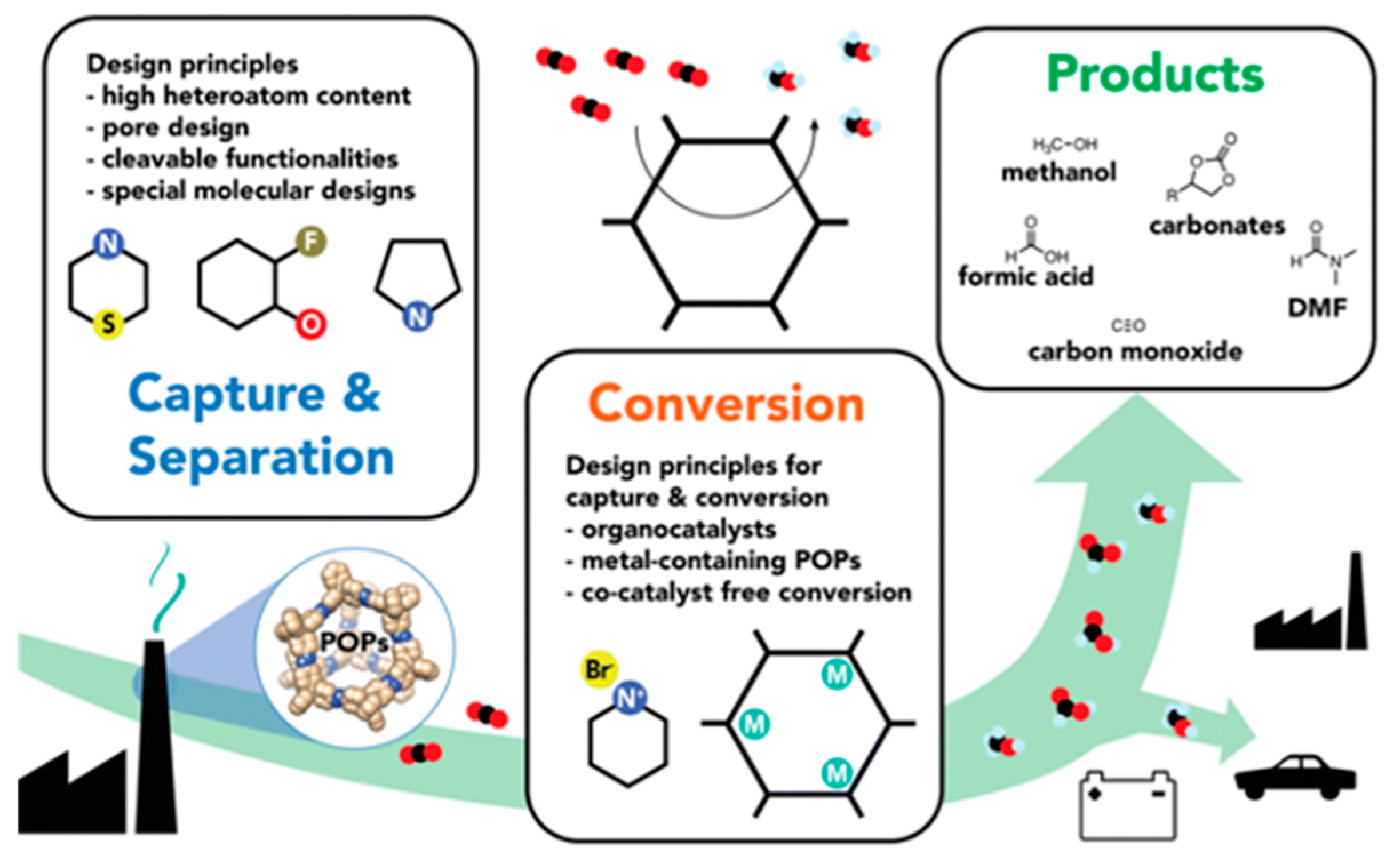
  131. Song, K.S.; Fritz, P.W.; Coskun, A. Porous Organic Polymers for CO2 Capture, Separation and Conversion. Chem. Soc. Rev. 2022, 51, 9831–9852. [Google Scholar] [CrossRef] [PubMed]
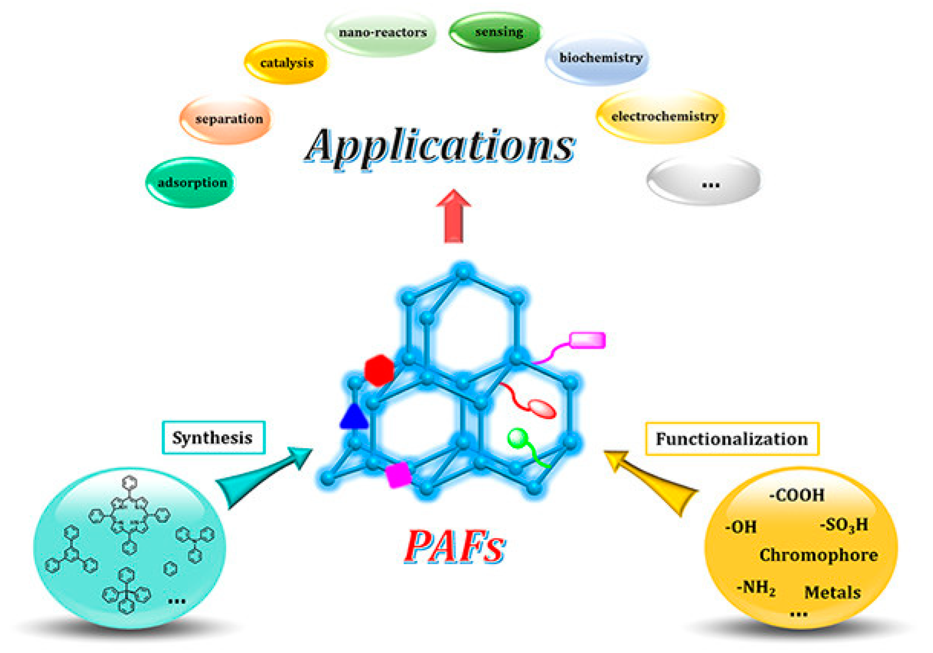
  132. Tian, Y.; Zhu, G. Porous Aromatic Frameworks (PAFs). Chem. Rev. 2020, 120, 8934–8986. [Google Scholar] [CrossRef]
  133. Babarao, R.; Dai, S.; Jiang, D. Functionalizing Porous Aromatic Frameworks with Polar Organic Groups for High-Capacity and Selective CO2 Separation: A Molecular Simulation Study. Langmuir 2011, 27, 3451–3460. [Google Scholar] [CrossRef]
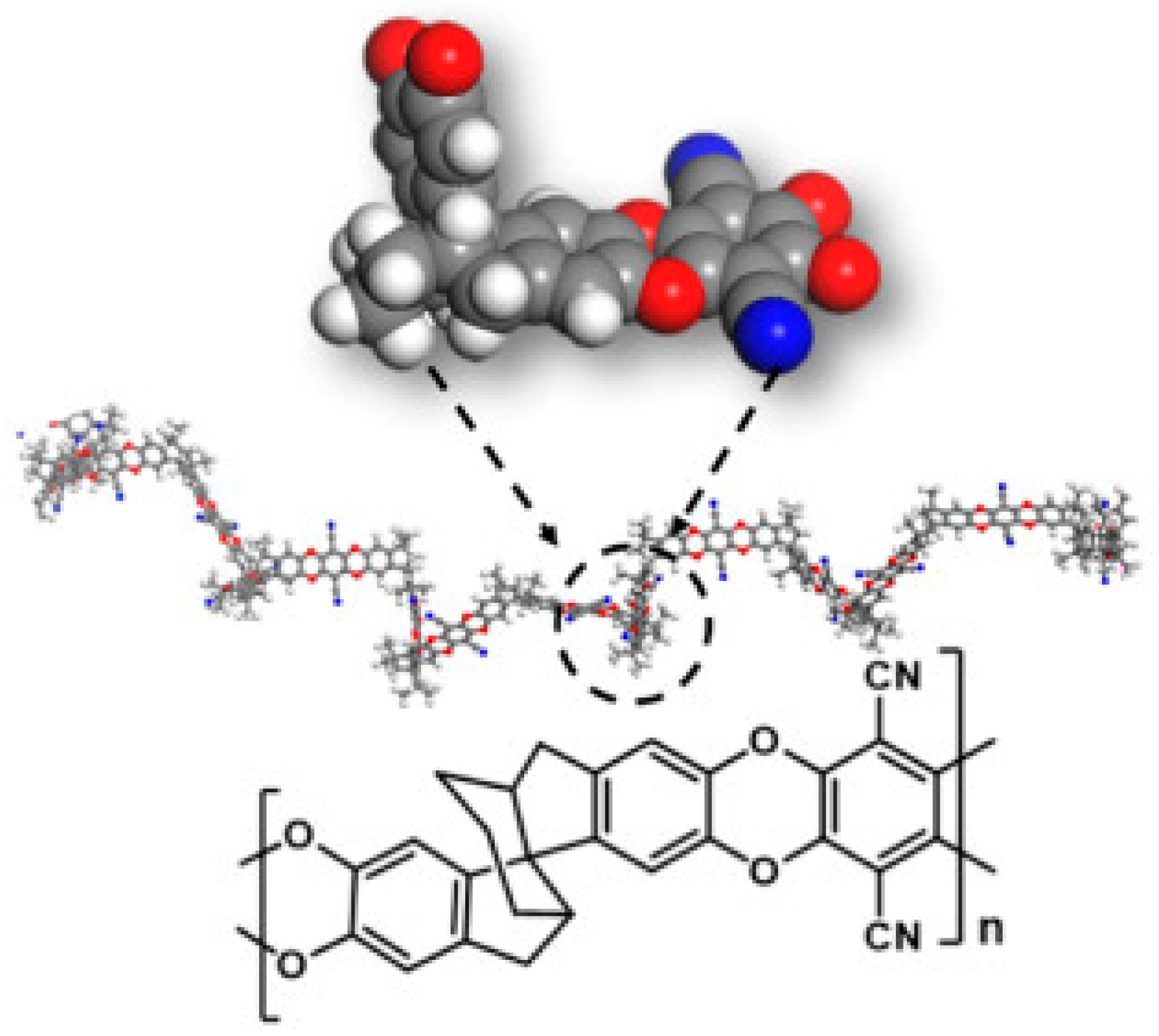
  134. Yu, C.; Wang, Y.; Xia, Y.; Luo, S.; Ma, X.; Yin, B.H.; Wang, X. Polymers of Intrinsic Microporosity with Internal Dihedral Lock for Efficient Gas Separation. Adv. Membr. 2024, 4, 100097. [Google Scholar] [CrossRef]
  135. Arabi Shamsabadi, A.; Rezakazemi, M.; Seidi, F.; Riazi, H.; Aminabhavi, T.; Soroush, M. Next Generation Polymers of Intrinsic Microporosity with Tunable Moieties for Ultrahigh Permeation and Precise Molecular CO2 Separation. Prog. Energy Combust. Sci. 2021, 84, 100903. [Google Scholar] [CrossRef]
  136. Yan, Q.; Lin, Y.; Wu, P.; Zhao, L.; Cao, L.; Peng, L.; Kong, C.; Chen, L. Designed Synthesis of Functionalized Two-Dimensional Metal–Organic Frameworks with Preferential CO2 Capture. Chempluschem 2013, 78, 86–91. [Google Scholar] [CrossRef]
  137. Chakraborty, G.; Das, P.; Mandal, S.K. Efficient and Highly Selective CO2 Capture, Separation, and Chemical Conversion under Ambient Conditions by a Polar-Group-Appended Copper(II) Metal–Organic Framework. Inorg. Chem. 2021, 60, 5071–5080. [Google Scholar] [CrossRef]
  138. Khan, N.A.; Jhung, S.H. Adsorptive Removal and Separation of Chemicals with Metal-Organic Frameworks: Contribution of π-Complexation. J. Hazard. Mater. 2017, 325, 198–213. [Google Scholar] [CrossRef] [PubMed]
  139. Gupta, V.; Mandal, S.K. Effect of Unsaturated Metal Site Modulation in Highly Stable Microporous Materials on CO2 Capture and Fixation. Inorg. Chem. 2022, 61, 3086–3096. [Google Scholar] [CrossRef]
  140. Kökçam-Demir, Ü.; Goldman, A.; Esrafili, L.; Gharib, M.; Morsali, A.; Weingart, O.; Janiak, C. Coordinatively Unsaturated Metal Sites (Open Metal Sites) in Metal–Organic Frameworks: Design and Applications. Chem. Soc. Rev. 2020, 49, 2751–2798. [Google Scholar] [CrossRef] [PubMed]
  141. Zhai, L.; Yao, Y.; Ma, B.; Hasan, M.M.; Han, Y.; Mi, L.; Nagao, Y.; Li, Z. Accumulation of Sulfonic Acid Groups Anchored in Covalent Organic Frameworks as an Intrinsic Proton-Conducting Electrolyte. Macromol. Rapid Commun. 2022, 43, 2100590. [Google Scholar] [CrossRef]
  142. Liu, J.; Wang, N.; Ma, L. Recent Advances in Covalent Organic Frameworks for Catalysis. Chem. Asian J. 2020, 15, 338–351. [Google Scholar] [CrossRef]
  143. Sahoo, R.; Mondal, S.; Pal, S.C.; Mukherjee, D.; Das, M.C. Covalent-Organic Frameworks (COFs) as Proton Conductors. Adv. Energy Mater. 2021, 11, 2102300. [Google Scholar] [CrossRef]
  144. Duong, P.H.H.; Shin, Y.K.; Kuehl, V.A.; Afroz, M.M.; Hoberg, J.O.; Parkinson, B.; van Duin, A.C.T.; Li-Oakey, K.D. Molecular Interactions and Layer Stacking Dictate Covalent Organic Framework Effective Pore Size. ACS Appl. Mater. Interfaces 2021, 13, 42164–42175. [Google Scholar] [CrossRef] [PubMed]
  145. Deng, L.; Ding, Z.; Ye, X.; Jiang, D. Covalent Organic Frameworks: Chemistry of Pore Interface and Wall Surface Perturbation and Impact on Functions. Acc. Mater. Res. 2022, 3, 879–893. [Google Scholar] [CrossRef]
  146. Buyukcakir, O.; Seo, Y.; Coskun, A. Thinking Outside the Cage: Controlling the Extrinsic Porosity and Gas Uptake Properties of Shape-Persistent Molecular Cages in Nanoporous Polymers. Chem. Mater. 2015, 27, 4149–4155. [Google Scholar] [CrossRef]
  147. Je, S.H.; Buyukcakir, O.; Kim, D.; Coskun, A. Direct Utilization of Elemental Sulfur in the Synthesis of Microporous Polymers for Natural Gas Sweetening. Chem 2016, 1, 482–493. [Google Scholar] [CrossRef]
  148. Patel, H.A.; Je, S.H.; Park, J.; Jung, Y.; Coskun, A.; Yavuz, C.T. Directing the Structural Features of N2—Phobic Nanoporous Covalent Organic Polymers for CO2 Capture and Separation. Chem—A Eur. J. 2014, 20, 772–780. [Google Scholar] [CrossRef] [PubMed]
  149. Song, K.S.; Kim, D.; Polychronopoulou, K.; Coskun, A. Synthesis of Highly Porous Coordination Polymers with Open Metal Sites for Enhanced Gas Uptake and Separation. ACS Appl. Mater. Interfaces 2016, 8, 26860–26867. [Google Scholar] [CrossRef]
  150. Zhang, P.; Zhang, C.; Wang, L.; Dong, J.; Gai, D.; Wang, W.; Nguyen, T.S.; Yavuz, C.T.; Zou, X.; Zhu, G. Basic Alkylamine Functionalized PAF-1 Hybrid Membrane with High Compatibility for Superior CO2 Separation from Flue Gas. Adv. Funct. Mater. 2023, 33, 2210091. [Google Scholar] [CrossRef]
  151. Lu, W.; Yuan, D.; Sculley, J.; Zhao, D.; Krishna, R.; Zhou, H.-C. Sulfonate-Grafted Porous Polymer Networks for Preferential CO2 Adsorption at Low Pressure. J. Am. Chem. Soc. 2011, 133, 18126–18129. [Google Scholar] [CrossRef] [PubMed]
  152. Vopička, O.; Friess, K.; Hynek, V.; Sysel, P.; Zgažar, M.; Šípek, M.; Pilnáček, K.; Lanč, M.; Jansen, J.C.; Mason, C.R.; et al. Equilibrium and Transient Sorption of Vapours and Gases in the Polymer of Intrinsic Microporosity PIM-1. J. Memb. Sci. 2013, 434, 148–160. [Google Scholar] [CrossRef]
  153. Wang, X.; Guo, H.; Yu, C.; Jing, Y.; Han, Z.; Ma, X.; Yang, C.; Liu, M.; Zhai, D.; Zheng, D.; et al. Practical Enantioselective Synthesis of Chiroptical Polymers of Intrinsic Microporosity with Circular Polarized Luminescence. Macromolecules 2021, 54, 11180–11186. [Google Scholar] [CrossRef]
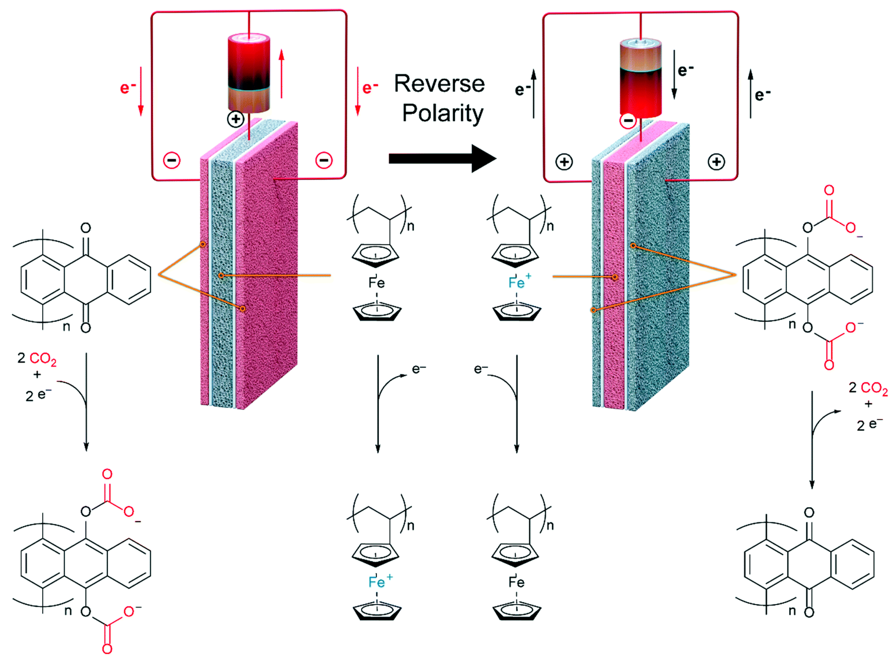
  154. Voskian, S.; Hatton, T.A. Faradaic Electro-Swing Reactive Adsorption for CO2 Capture. Energy Environ. Sci. 2019, 12, 3530–3547. [Google Scholar] [CrossRef]
  155. Gurkan, B.; Simeon, F.; Hatton, T.A. Quinone Reduction in Ionic Liquids for Electrochemical CO2 Separation. ACS Sustain. Chem. Eng. 2015, 3, 1394–1405. [Google Scholar] [CrossRef]
  156. Ranjan, R.; Olson, J.; Singh, P.; Lorance, E.D.; Buttry, D.A.; Gould, I.R. Reversible Electrochemical Trapping of Carbon Dioxide Using 4,4′-Bipyridine That Does Not Require Thermal Activation. J. Phys. Chem. Lett. 2015, 6, 4943–4946. [Google Scholar] [CrossRef]
  157. Rheinhardt, J.H.; Singh, P.; Tarakeshwar, P.; Buttry, D.A. Electrochemical Capture and Release of Carbon Dioxide. ACS Energy Lett. 2017, 2, 454–461. [Google Scholar] [CrossRef]
  158. Singh, P.; Rheinhardt, J.H.; Olson, J.Z.; Tarakeshwar, P.; Mujica, V.; Buttry, D.A. Electrochemical Capture and Release of Carbon Dioxide Using a Disulfide–Thiocarbonate Redox Cycle. J. Am. Chem. Soc. 2017, 139, 1033–1036. [Google Scholar] [CrossRef] [PubMed]
  159. Hatton, T.A.; Voskian, S. Electro-Swing Adsorption for CO2 Emissions Mitigation—From Concept to Start-Up. ECS Meet. Abstr. 2023, MA2023-01, 1760. [Google Scholar] [CrossRef]
  160. Wilcox, J. An Electro-Swing Approach. Nat. Energy 2020, 5, 121–122. [Google Scholar] [CrossRef]
  161. Biery, A.R.; Shokrollahzadeh Behbahani, H.; Green, M.D.; Knauss, D.M. Polydiallylammonium-Polysulfone Multiblock Copolymers for Moisture-Swing Direct Air Capture of Carbon Dioxide. ACS Appl. Polym. Mater. 2024, 6, 2649–2658. [Google Scholar] [CrossRef]
  162. Wang, T.; Lackner, K.S.; Wright, A.B. Moisture-Swing Sorption for Carbon Dioxide Capture from Ambient Air: A Thermodynamic Analysis. Phys. Chem. Chem. Phys. 2013, 15, 504–514. [Google Scholar] [CrossRef]
  163. Fasihi, M.; Efimova, O.; Breyer, C. Techno-Economic Assessment of CO2 Direct Air Capture Plants. J. Clean. Prod. 2019, 224, 957–980. [Google Scholar] [CrossRef]
  164. Hou, C.; Wu, Y.; Jiao, Y.; Huang, J.; Wang, T.; Fang, M.; Zhou, H. Integrated Direct Air Capture and CO2 Utilization of Gas Fertilizer Based on Moisture Swing Adsorption. J. Zhejiang Univ.-Sci. A 2017, 18, 819–830. [Google Scholar] [CrossRef]
  165. Shi, X.; Xiao, H.; Kanamori, K.; Yonezu, A.; Lackner, K.S.; Chen, X. Moisture-Driven CO2 Sorbents. Joule 2020, 4, 1823–1837. [Google Scholar] [CrossRef]
  166. Shi, X.; Xiao, H.; Liao, X.; Armstrong, M.; Chen, X.; Lackner, K.S. Humidity Effect on Ion Behaviors of Moisture-Driven CO2 Sorbents. J. Chem. Phys. 2018, 149, 164708. [Google Scholar] [CrossRef] [PubMed]
  167. Wang, T.; Wang, X.; Hou, C.; Liu, J. Quaternary Functionalized Mesoporous Adsorbents for Ultra-High Kinetics of CO2 Capture from Air. Sci. Rep. 2020, 10, 21429. [Google Scholar] [CrossRef] [PubMed]
  168. Li, G.; Yao, J. Snap-Off during Imbibition in Porous Media: Mechanisms, Influencing Factors, and Impacts. Eng 2023, 4, 2896–2925. [Google Scholar] [CrossRef]
  169. Yao, J.; Oakey, J. Geometrically-Mediated Snap-off of Water-in-Oil Emulsion Droplets in Microfluidic Flow Focusing Devices. J. Oil Gas Petrochem. Sci. 2018, 1, 42. [Google Scholar] [CrossRef] [PubMed]
  170. Yao, J. A Microfluidic Model for Visualizing Snap-off During Imbibition. Ph.D. Dissertation, University of Wyoming, Laramie, WY, USA, 2017. [Google Scholar]
  171. Qu, Z.; Yao, J.; Yang, Y.; Wang, B.; He, L. Laboratory Experiments of a Microfluidic Model for Imbibition. J. Petrochem. Univ. 2014, 37, 64–66. [Google Scholar]
  172. Fu, Q.; Halim, A.; Kim, J.; Scofield, J.M.P.; Gurr, P.A.; Kentish, S.E.; Qiao, G.G. Highly Permeable Membrane Materials for CO2 Capture. J. Mater. Chem. A Mater. 2013, 1, 13769. [Google Scholar] [CrossRef]
  173. Merkel, T.C.; Lin, H.; Wei, X.; Baker, R. Power Plant Post-Combustion Carbon Dioxide Capture: An Opportunity for Membranes. J. Memb. Sci. 2010, 359, 126–139. [Google Scholar] [CrossRef]
  174. Yoo, M.J.; Kim, K.H.; Lee, J.H.; Kim, T.W.; Chung, C.W.; Cho, Y.H.; Park, H.B. Ultrathin Gutter Layer for High-Performance Thin-Film Composite Membranes for CO2 Separation. J. Memb. Sci. 2018, 566, 336–345. [Google Scholar] [CrossRef]
  175. Lin, H.; Van Wagner, E.; Freeman, B.D.; Toy, L.G.; Gupta, R.P. Plasticization-Enhanced Hydrogen Purification Using Polymeric Membranes. Science 2006, 311, 639–642. [Google Scholar] [CrossRef] [PubMed]
  176. Li, S.; Wang, Z.; Zhang, C.; Wang, M.; Yuan, F.; Wang, J.; Wang, S. Interfacially Polymerized Thin Film Composite Membranes Containing Ethylene Oxide Groups for CO2 Separation. J. Memb. Sci. 2013, 436, 121–131. [Google Scholar] [CrossRef]
  177. Fujikawa, S.; Ariyoshi, M.; Selyanchyn, R.; Kunitake, T. Ultra-Fast, Selective CO2 Permeation by Free-Standing Siloxane Nanomembranes. Chem. Lett. 2019, 48, 1351–1354. [Google Scholar] [CrossRef]
  178. Das, M.; Perry, J.D.; Koros, W.J. Gas-Transport-Property Performance of Hybrid Carbon Molecular Sieve−Polymer Materials. Ind. Eng. Chem. Res. 2010, 49, 9310–9321. [Google Scholar] [CrossRef]
  179. Clarizia, G.; Algieri, C.; Regina, A.; Drioli, E. Zeolite-Based Composite PEEK-WC Membranes: Gas Transport and Surface Properties. Microporous Mesoporous Mater. 2008, 115, 67–74. [Google Scholar] [CrossRef]
  180. Li, Y.; Chung, T.; Cao, C.; Kulprathipanja, S. The Effects of Polymer Chain Rigidification, Zeolite Pore Size and Pore Blockage on Polyethersulfone (PES)-Zeolite A Mixed Matrix Membranes. J. Memb. Sci. 2005, 260, 45–55. [Google Scholar] [CrossRef]
  181. Erucar, I.; Yilmaz, G.; Keskin, S. Recent Advances in Metal–Organic Framework-Based Mixed Matrix Membranes. Chem. Asian J. 2013, 8, 1692–1704. [Google Scholar] [CrossRef] [PubMed]
  182. Xin, Q.; Zhang, X.; Shao, W.; Li, H.; Zhang, Y. COF-Based MMMs with Light-Responsive Properties Generating Unexpected Surface Segregation for Efficient SO2/N2 Separation. J. Memb. Sci. 2023, 665, 121109. [Google Scholar] [CrossRef]
  183. Zhang, Y.; Ma, L.; Lv, Y.; Tan, T. Facile Manufacture of COF-Based Mixed Matrix Membranes for Efficient CO2 Separation. Chem. Eng. J. 2022, 430, 133001. [Google Scholar] [CrossRef]
  184. Nasir, R.; Mukhtar, H.; Man, Z.; Mohshim, D.F. Material Advancements in Fabrication of Mixed-Matrix Membranes. Chem. Eng. Technol. 2013, 36, 717–727. [Google Scholar] [CrossRef]
  185. Perez, E.; Karunaweera, C.; Musselman, I.; Balkus, K.; Ferraris, J. Origins and Evolution of Inorganic-Based and MOF-Based Mixed-Matrix Membranes for Gas Separations. Processes 2016, 4, 32. [Google Scholar] [CrossRef]
  186. Goh, P.S.; Ismail, A.F.; Sanip, S.M.; Ng, B.C.; Aziz, M. Recent Advances of Inorganic Fillers in Mixed Matrix Membrane for Gas Separation. Sep. Purif. Technol. 2011, 81, 243–264. [Google Scholar] [CrossRef]
  187. Ban, Y.; Li, Z.; Li, Y.; Peng, Y.; Jin, H.; Jiao, W.; Guo, A.; Wang, P.; Yang, Q.; Zhong, C.; et al. Confinement of Ionic Liquids in Nanocages: Tailoring the Molecular Sieving Properties of ZIF-8 for Membrane-Based CO2 Capture. Angew. Chem. Int. Ed. 2015, 54, 15483–15487. [Google Scholar] [CrossRef] [PubMed]
  188. Lin, R.; Ge, L.; Diao, H.; Rudolph, V.; Zhu, Z. Ionic Liquids as the MOFs/Polymer Interfacial Binder for Efficient Membrane Separation. ACS Appl. Mater. Interfaces 2016, 8, 32041–32049. [Google Scholar] [CrossRef] [PubMed]
  189. Smith, S.J.D.; Lau, C.H.; Mardel, J.I.; Kitchin, M.; Konstas, K.; Ladewig, B.P.; Hill, M.R. Physical Aging in Glassy Mixed Matrix Membranes; Tuning Particle Interaction for Mechanically Robust Nanocomposite Films. J. Mater. Chem. A Mater. 2016, 4, 10627–10634. [Google Scholar] [CrossRef]
  190. Mahdi, E.M.; Tan, J.-C. Dynamic Molecular Interactions between Polyurethane and ZIF-8 in a Polymer-MOF Nanocomposite: Microstructural, Thermo-Mechanical and Viscoelastic Effects. Polymer 2016, 97, 31–43. [Google Scholar] [CrossRef]
  191. Shan, M.; Liu, X.; Wang, X.; Yarulina, I.; Seoane, B.; Kapteijn, F.; Gascon, J. Facile Manufacture of Porous Organic Framework Membranes for Precombustion CO2 Capture. Sci. Adv. 2018, 4, aau1698. [Google Scholar] [CrossRef] [PubMed]
  192. Gao, X.; Zou, X.; Ma, H.; Meng, S.; Zhu, G. Highly Selective and Permeable Porous Organic Framework Membrane for CO2 Capture. Adv. Mater. 2014, 26, 3644–3648. [Google Scholar] [CrossRef] [PubMed]
  193. Zhao, R.; Wu, H.; Yang, L.; Ren, Y.; Liu, Y.; Qu, Z.; Wu, Y.; Cao, L.; Chen, Z.; Jiang, Z. Modification of Covalent Organic Frameworks with Dual Functions Ionic Liquids for Membrane-Based Biogas Upgrading. J. Memb. Sci. 2020, 600, 117841. [Google Scholar] [CrossRef]
  194. Liu, Y.; Wu, H.; Wu, S.; Song, S.; Guo, Z.; Ren, Y.; Zhao, R.; Yang, L.; Wu, Y.; Jiang, Z. Multifunctional Covalent Organic Framework (COF)-Based Mixed Matrix Membranes for Enhanced CO2 Separation. J. Memb. Sci. 2021, 618, 118693. [Google Scholar] [CrossRef]
  195. Keskin, S.; Alsoy Altinkaya, S. A Review on Computational Modeling Tools for MOF-Based Mixed Matrix Membranes. Computation 2019, 7, 36. [Google Scholar] [CrossRef]
  196. Peters, L.; Hussain, A.; Follmann, M.; Melin, T.; Hägg, M.-B. CO2 Removal from Natural Gas by Employing Amine Absorption and Membrane Technology—A Technical and Economical Analysis. Chem. Eng. J. 2011, 172, 952–960. [Google Scholar] [CrossRef]
  197. Green, M.; Behbahani, H.S.; Yang, Y. Ammonium-Functionalized Polysulfone Copolymers for Moisture-Swing CO2 Capture 2023. U.S. Patent Application 17/793,925, 9 February 2023. [Google Scholar]
  198. Green, M.; Korah, M.M.; Culp, K. Polymeric Materials for Carbon Dioxide Capture 2024. U.S. Patent Application 18/361,657, 1 February 2024. [Google Scholar]
  199. IEA. Direct Air Capture. Available online: https://www.iea.org/energy-system/carbon-capture-utilisation-and-storage/direct-air-capture (accessed on 25 April 2024).
  200. IEA. CCUS around the World in 2021; IEA: Paris, France, 2021; Available online: https://www.iea.org/reports/ccus-around-the-world-in-2021 (accessed on 1 April 2021).
  201. Carbon Engineering Carbon Engineering Begins Work on Supporting Multi-Million Tonne Direct Air Capture Facilities in South Texas. Available online: https://carbonengineering.com/news-updates/multi-million-tonne-south-texas/ (accessed on 31 October 2022).
  202. Baker Hughes Baker Hughes and HIF Global to Collaborate on Direct Air Capture Technology. Available online: https://investors.bakerhughes.com/node/27516/pdf (accessed on 7 March 2023).
  203. CarbonCapture Project Bison. Available online: https://www.carboncapture.com/project-bison (accessed on 8 September 2022).
  204. Energy Monitor Global Thermostat Unveils Direct Air Capture Plant in Colorado. Available online: https://www.energymonitor.ai/carbon-removal/global-thermostat-unveils-direct-air-capture-plant-in-colorado/?cf-view (accessed on 17 April 2023).
  205. Carbon Engineering Engineering Begins on UK’s First Large-Scale Facility That Captures Carbon Dioxide out of the Atmosphere. Available online: https://carbonengineering.com/news-updates/uks-first-large-scale-dac-facility/ (accessed on 23 June 2021).
  206. Carbon Engineering New Partnership to Deploy Large-Scale Direct Air Capture in Norway. Available online: https://carbonengineering.com/news-updates/partnership-dac-norway/ (accessed on 23 November 2021).
  207. Climeworks Capricorn. Available online: https://climeworks.com/plant-capricorn (accessed on 15 May 2017).
  208. Climeworks Arctic Fox. Available online: https://climeworks.com/plant-arctic-fox (accessed on 15 October 2017).
  209. Climeworks Orca: The First Large-Scale Plant. Available online: https://climeworks.com/plant-orca (accessed on 8 September 2021).
  210. Climeworks Mammoth: Our Newest Facility. Available online: https://climeworks.com/plant-mammoth (accessed on 28 June 2022).
  211. van der Giesen, C.; Kleijn, R.; Kramer, G.J. Energy and Climate Impacts of Producing Synthetic Hydrocarbon Fuels from CO2. Environ. Sci. Technol. 2014, 48, 7111–7121. [Google Scholar] [CrossRef] [PubMed]
  212. König, D.H.; Baucks, N.; Dietrich, R.-U.; Wörner, A. Simulation and Evaluation of a Process Concept for the Generation of Synthetic Fuel from CO2 and H2. Energy 2015, 91, 833–841. [Google Scholar] [CrossRef]
  213. Ishaq, H.; Crawford, C. CO2-based Alternative Fuel Production to Support Development of CO2 Capture, Utilization and Storage. Fuel 2023, 331, 125684. [Google Scholar] [CrossRef]
  214. Al-Sakkari, E.G.; Ragab, A.; Dagdougui, H.; Boffito, D.C.; Amazouz, M. Carbon Capture, Utilization and Sequestration Systems Design and Operation Optimization: Assessment and Perspectives of Artificial Intelligence Opportunities. Sci. Total Environ. 2024, 917, 170085. [Google Scholar] [CrossRef] [PubMed]
  215. Yan, Y.; Borhani, T.N.; Subraveti, S.G.; Pai, K.N.; Prasad, V.; Rajendran, A.; Nkulikiyinka, P.; Asibor, J.O.; Zhang, Z.; Shao, D.; et al. Harnessing the Power of Machine Learning for Carbon Capture, Utilisation, and Storage (CCUS)—A State-of-the-Art Review. Energy Environ. Sci. 2021, 14, 6122–6157. [Google Scholar] [CrossRef]
  216. Al-Sakkari, E.G.; Ragab, A.; So, T.M.Y.; Shokrollahi, M.; Dagdougui, H.; Navarri, P.; Elkamel, A.; Amazouz, M. Machine Learning-Assisted Selection of Adsorption-Based Carbon Dioxide Capture Materials. J. Environ. Chem. Eng. 2023, 11, 110732. [Google Scholar] [CrossRef]
  217. Anderson, R.; Rodgers, J.; Argueta, E.; Biong, A.; Gómez-Gualdrón, D.A. Role of Pore Chemistry and Topology in the CO2 Capture Capabilities of MOFs: From Molecular Simulation to Machine Learning. Chem. Mater. 2018, 30, 6325–6337. [Google Scholar] [CrossRef]
Figure 1. Global greenhouse gas emissions by sector. Reproduced based on data from [5] under the CC BY license.
Eng 05 00069 g001
Figure 2. Schematic diagram of CO2 capture in DAC.
Eng 05 00069 g002
Figure 3. Schematic diagram of L-DAC processes. Technological parameters are indicated in blue, and electricity demands are indicated in red with the unit of megawatts (MW), both based on industry-scale conditions [41]. Reproduced with permission from [43]. Copyright 2023, Elsevier.
Eng 05 00069 g003
Figure 4. Simplified schematic of the air contactor structure used in L-DAC technology.
Eng 05 00069 g004
Figure 5. Schematic diagram of S-DAC’s process flow. Reproduced with permission from [92] under the CC BY license.
Eng 05 00069 g005
Figure 6. Chemical structures of commonly employed amines for S-DAC: (a) poly(allylamine) (PAA); (b) poly(glycidyl amine) (PGA); (c) poly(propylene guanidine) (PPG); (d) tetraethylenepentamine (TEPA); (e) polyethyleneimine (PEI).
Eng 05 00069 g006
Figure 7. Molecular structures of some support materials used in synthesizing PEI-modified sorbents: (a) (3-aminopropyl)trimethoxysilane; (b) tetraethyl orthotitanate; (c) diethanolamine (DEA).
Eng 05 00069 g007
Figure 8. Mechanistic illustration of CO2 capture by some materials with inherent pore structures: (a) CO2 capture by CBMs. Reprinted with permission from [125]. Copyright 2023, Elsevier. (b) CO2 capture by zeolites. Reprinted with permission from [116]. Copyright 2020, Elsevier. (c) CO2 capture by boron nitride nanomaterials. Reproduced with permission from [119]. Copyright 2013, American Chemical Society. (d) CO2 capture by Cu-loaded porous boron nitride nanofibers. Reproduced with permission from [120]. Copyright 2020, American Chemical Society.
Eng 05 00069 g008
Figure 9. Schematic diagram of MOFs’ formation and CO2 capture mechanism: (a) Formation of MOF. (b) Selective gas adsorption in MOFs. Reprinted with permission from [126]. Copyright 2020, Elsevier.
Eng 05 00069 g009
Figure 10. Schematic diagram of COF-609 chemical structure and its CO2 capture mechanism. Reprinted with permission from [130]. Copyright 2022, American Chemical Society.
Eng 05 00069 g010
Figure 11. Schematic illustration of the design principles of POPs for CO2 capture and separation, and subsequent conversion of CO2. Reproduced with permission from [131] under the CC BY-NC license.
Eng 05 00069 g011
Figure 12. Schematic illustration of the structure and applications of PAFs. Reprinted with permission from [132]. Copyright 2020, American Chemical Society.
Eng 05 00069 g012
Figure 13. Chemical structure of CCS-PIM featuring a non-distorted chain structure with well-regulated micropore spaces for enhanced CO2 separation performance. Reprinted with permission from [134] under the CC BY-NC license.
Eng 05 00069 g013
Figure 14. Schematic diagram of a single ESA electrochemical cell for CO2 capture and release. Reprinted with permission from [154] under the CC BY-NC license.
Eng 05 00069 g014
Figure 15. Schematic diagram of MSA for CO2 capture and release with potential moisture-driven sorbents. Reprinted with permission from [165]. Copyright 2020, Elsevier.
Eng 05 00069 g015
Figure 16. Schematic illustration of a thin-film composite membrane for m-DAC. Reprinted with permission from [33] under the CC BY license.
Eng 05 00069 g016
Table 1. Comparison of DAC and other CO2 capture technologies [2].
TechnologyApplicabilityAdvantageDisadvantage
DACNo significant limitationsFlexible deployment options;
Capture of low-concentration CO2;
Integration with renewable energy
High investment costs;
High operating costs;
Technological limitations
Pre-combustion captureIntegrated gasification combined cycle (IGCC) power plantMature technology;
High efficiency and easy separation
Limited applicability
Post-combustion capturePulverized coal (PC) power plant;
Natural gas combined cycle (NGCC) power plant;
Fossil fuel power plant
Mature technology;
Wide applicability to existing plants;
Retrofit application
Generation inefficiency
Oxy-fuel combustion capturePulverized coal (PC) power plant;
Integrated gasification combined cycle (IGCC) power plant
Mature technology;
High purity and concentration;
Simple procedures;
Retrofit and repowering option
High investment costs due to additional equipment required
Table 2. Summary of representative review studies on DAC.
AuthorsContentsYearReferences
Bisotti et al.This study introduces the challenges in scaling up DAC technologies from pilot to industrial scale, along with limiting factors such as the supply of critical materials and competition with the energy transition.2024[35]
An et al.This study highlights the critical role of energy efficiency and regeneration energy in enabling DAC for negative emissions and discusses potential methods to lower the regeneration energy demand.2023[36]
Ozkan et al.This study provides an overview of current commercial DAC technologies, highlighting the need for technological advancements to reduce costs and meet global climate goals.2022[37]
Erans et al.This study explores the role of DAC as a carbon dioxide removal technology in mitigating CO2 emissions, highlighting its potential alongside other negative emissions technologies and identifying research challenges across the process technology, techno-economic, and socio-political domains.2022[27]
Chauvy et al.This study evaluates the environmental and economic performance of DAC through life-cycle and techno-economic assessments, highlighting potential improvements to enhance DAC’s efficiency and affordability.2022[38]
CustelceanThis study explores the solvent-based approach to DAC, detailing its chemistry, engineering aspects, and solvent options, along with regeneration methods, to assess its potential for large-scale CO2 removal.2022[31]
McQueen et al.This study explores the potential of DAC using solid sorbents and liquid solvents to combat climate change, analyzing their properties and deployment considerations to enable rapid scaling and cost reduction.2021[39]
Table 3. Comparison of different DAC technologies.
TechnologyPrincipleCommonly Employed MaterialAdvantageDisadvantage
L-DACThe liquid solvent reacts with CO2 to form carbonates for capture, and it releases CO2 upon heatingAlkaline solutionsLarge-scale operation;
Continuous operation at steady state without interruption;
Low-cost raw materials with good selectivity and capture capacity
High temperature requirement;
High energy consumption;
Requirement for corrosion-resistant equipment
S-DACThe solid sorbent captures CO2 from ambient air at room temperature and atmospheric pressure, and then releases CO2 under low pressure and moderate temperatures through a temperature-vacuum swing processAmine-based sorbentsModular and scalable operations;
Lower energy consumption than L-DAC
Batch operations causing complex plant structures;
Special construction required for cycling temperature and pressure conditions;
High construction costs;
Sorbents with low sustainability
Emerging DAC technologiesESAThe electrochemical cell utilizes charge modulation to control the adsorption and desorption processes, capturing CO2 when negatively charged and releasing it when positively chargedElectrochemical cell;
Electrode materials
Space-efficient structure;
Convenient operation with no additional equipment required;
Low energy consumption;
Effective capture capacity;
Good durability
High investment costs
MSAThe moisture-sensitive sorbents rely on chemical reactions between carbonate ions and water molecules to alter energy states, facilitating CO2 capture in dry conditions and CO2 release in wet conditionsIon-exchange resinsLow energy consumption;
Convenient integration with low-carbon energies
Consumption of a large amount of water;
Sensitive to practical weather conditions
m-DACThe membrane utilizes selective permeability properties to enable the separation and capture of CO2 from airUltrathin-film composite (TFC) membrane;
Mixed-matrix membranes (MMMs)
Low energy consumption;
Low carbon footprint
Low throughput;
High material costs
Table 4. Representative DAC facilities in North America.
ProjectLocationOperating CompanyCapture CapacityCapture TechnologyTypes of Utilization and StorageReferences
STRAROS DAC1Texas Permian Basin1 PointFive (a subsidiary of Occidental) and Carbon Engineering1.0 Mt CO2/yearL-DACGeological storage[200]
Oxy-CE Kleberg County projectGulf Coast region, Texas, US1 PointFive (a subsidiary of Occidental) and Carbon Engineering30 Mt CO2/yearL-DACGeological storage[201]
HIF eFuels Matogorda County projectMatagorda County, Texas, USHighly Innovative Fuels (HIF) and Baker Hughes25 Mt CO2/yearMOFs as primary sorbentseFuel production[202]
Project BasinWyoming, USCarbonCapture and Frontier Carbon Solutions5-Megaton-scaleS-DAC as the primary method, possibly combined with MOFs and hybrid solutionsDeep saline aquifer storage[199,203]
Adams County projectColorado, USGlobal Thermostat1000 tonnes CO2/yearS-DACValuable products[199,204]
DAC R&D facilitySquamish, British Columbia, CanadaCarbon Engineering1 Mt CO2/yearL-DACFuel production[41]
Table 5. Representative DAC facilities in Europe.
ProjectLocationOperating CompanyCapture CapacityCapture TechnologyTypes of Utilization and StorageReferences
North-East Scotland DAC ProjectUnited KingdomStoregga and Carbon Engineering500,000 to 1,000,000 tonnes of CO2/yearL-DACGeological storage[205]
Kollsnes DAC projectNorwayCarbon Removal, Carbon Engineering, and Oxy Low Carbon Ventures500,000 to 1,000,000 tonnes of CO2/yearL-DACOffshore geological storage[206]
CapricornHinwil, SwitzerlandClimeworksSeveral hundred tons of CO2/yearS-DACVegetable fertilization and beverage industry[207]
Arctic FoxHellishidi, IcelandClimeworks50 tons of CO2/yearS-DACGeological stroage[208]
OrcaHellisheidi, IcelandClimeworks4000 tons of CO2/yearS-DACGeological storage[209]
MammothHellisheidi, IcelandClimeworks and Carbfix36,000 tons of CO2/yearS-DACGeological storage[210]
Disclaimer/Publisher’s Note: The statements, opinions and data contained in all publications are solely those of the individual author(s) and contributor(s) and not of MDPI and/or the editor(s). MDPI and/or the editor(s) disclaim responsibility for any injury to people or property resulting from any ideas, methods, instructions or products referred to in the content.

