

Towards Sustainable Perovskite Solar Cells: Lead-Free High Efficiency Designs with Tin and Germanium

Abstract
:1. Introduction
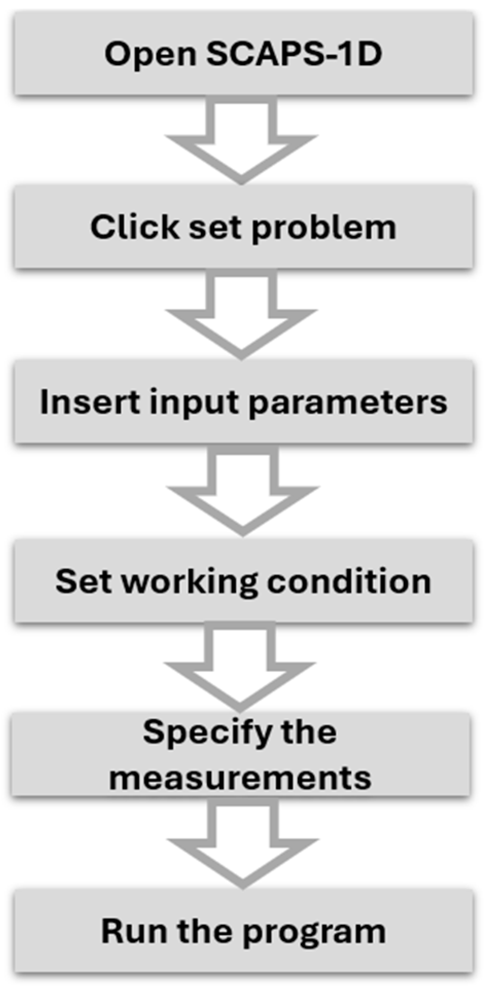
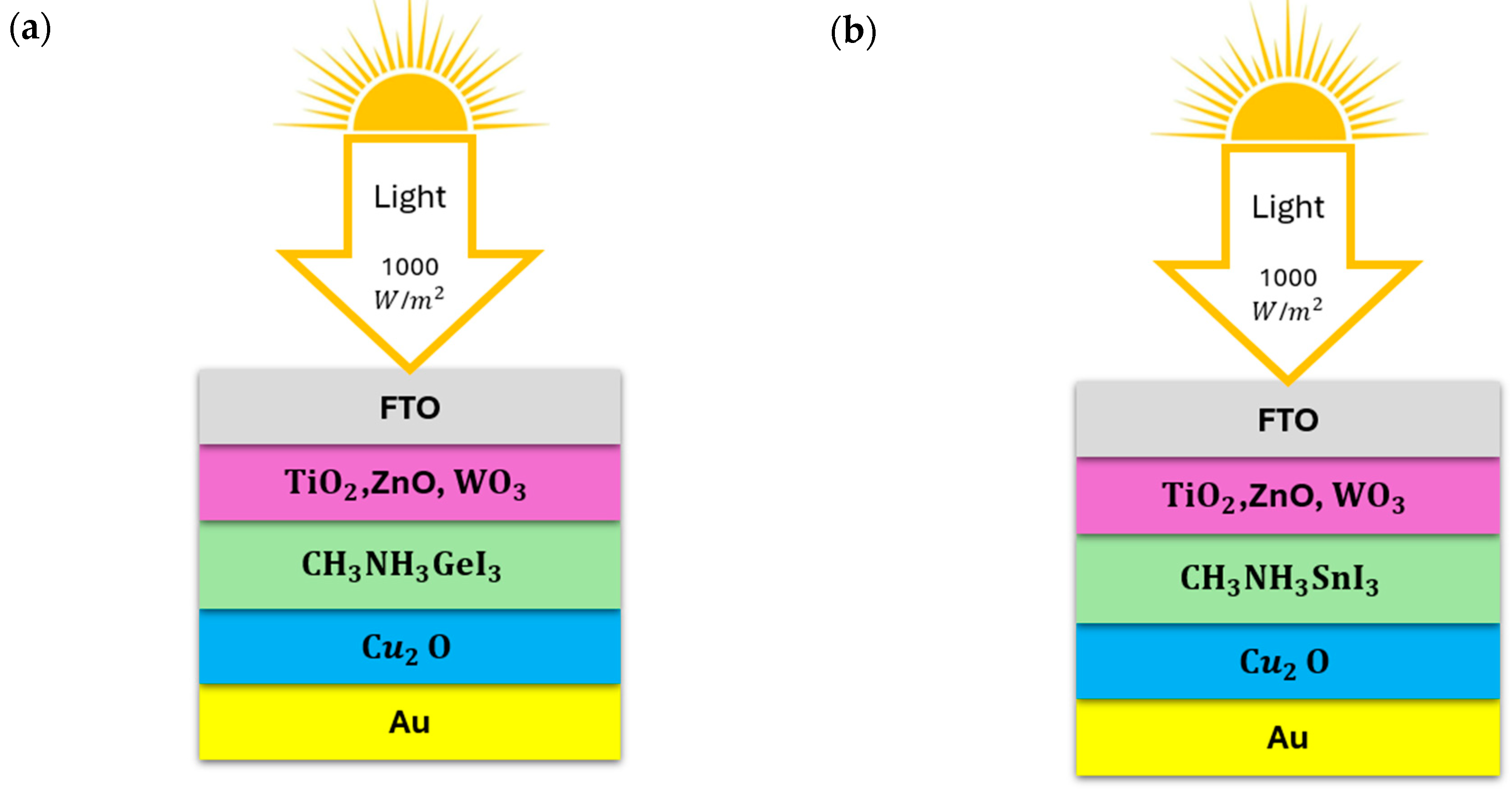
2. Materials and Methods
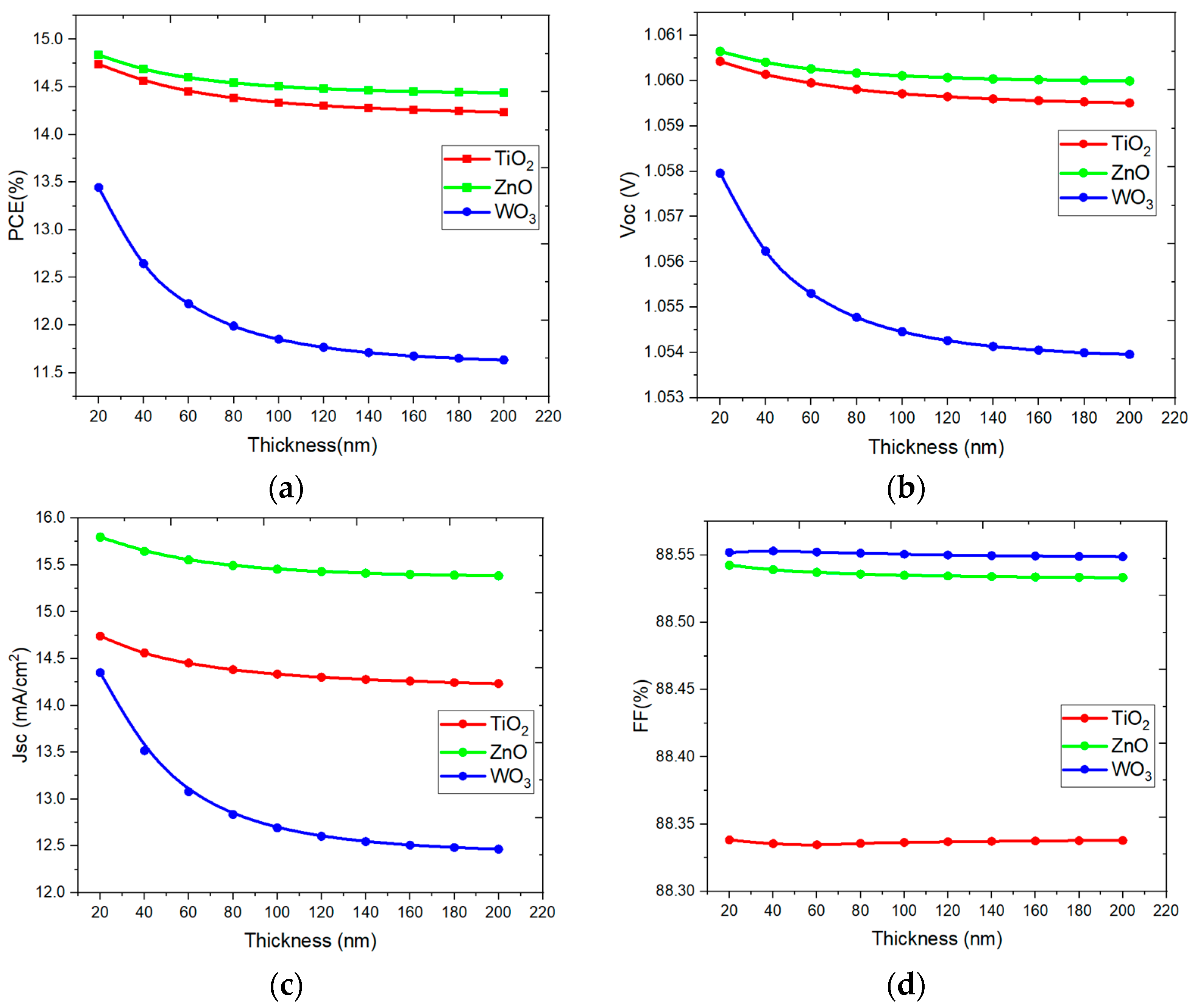
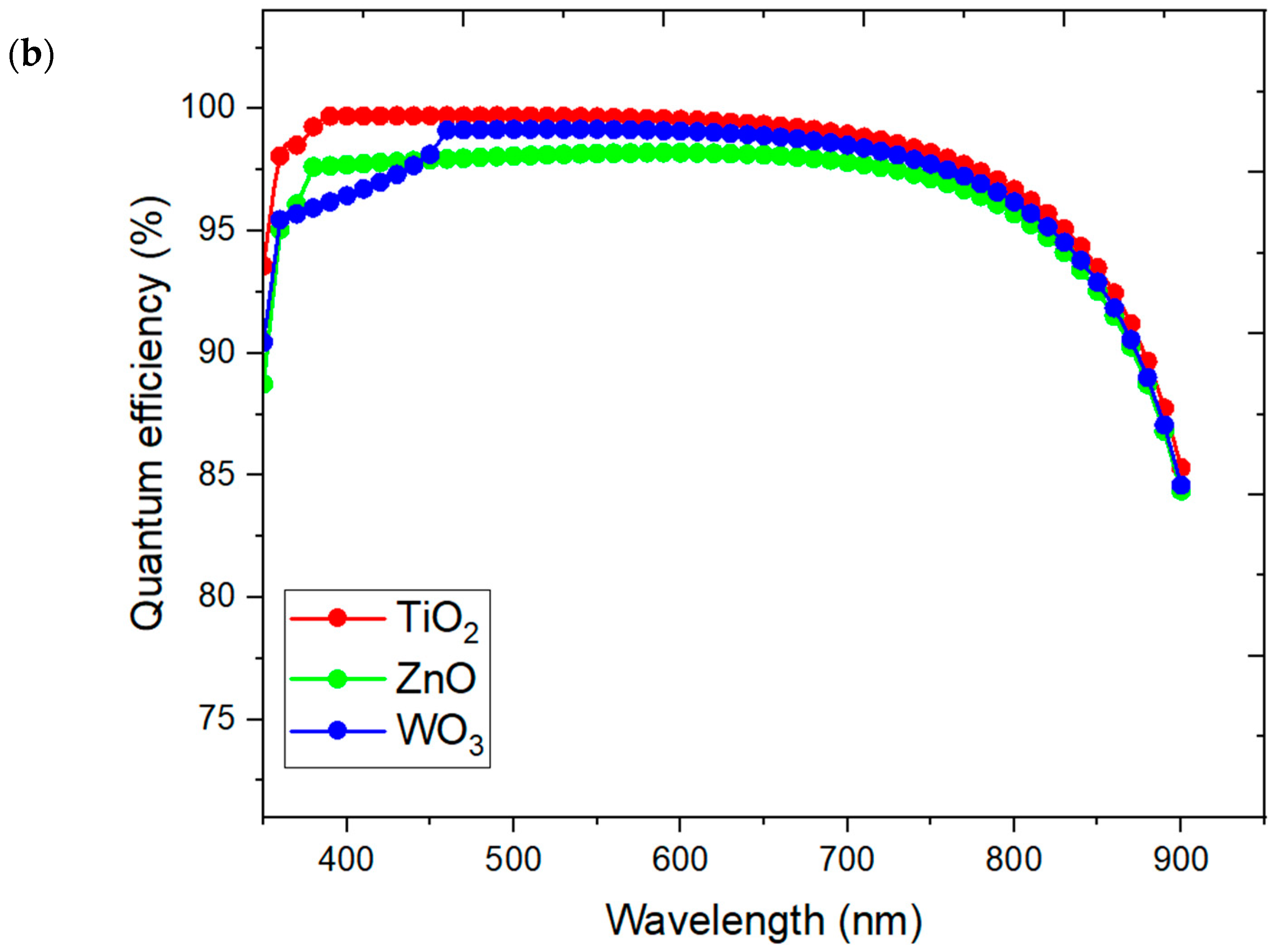
3. Results and Discussion
4. Conclusions
Author Contributions
Funding
Institutional Review Board Statement
Informed Consent Statement
Data Availability Statement
Acknowledgments
Conflicts of Interest
References
- Bhattacharya, S.; John, S. Beyond 30% Conversion Efficiency in Silicon Solar Cells: A Numerical Demonstration. Sci. Rep. 2019, 9, 12482. [Google Scholar] [CrossRef] [PubMed]
- Grätzel, M. The light and shade of perovskite solar cells. Nat. Mater. 2014, 13, 838–842. [Google Scholar] [CrossRef] [PubMed]
- Singh, A.; Umakanth, V.; Tyagi, N.; Baghel, A.K.; Kumar, S. Comparative study of commercial crystalline solar cells. Results Opt. 2023, 11, 100379. [Google Scholar] [CrossRef]
- Arul Prishya, A.S.; Chopra, L.; Manikanika. Comprehensive review on uses of silicon dioxide in solar cell. Mater. Today Proc. 2022, 72, 1471–1478. [Google Scholar] [CrossRef]
- Suresh Kumar, N.; Chandra Babu Naidu, K. A review on perovskite solar cells (PSCs), materials and applications. J. Mater. 2021, 7, 940–956. [Google Scholar] [CrossRef]
- Wu, T.; Qin, Z.; Wang, Y.; Wu, Y.; Chen, W.; Zhang, S.; Cai, M.; Dai, S.; Zhang, J.; Liu, J.; et al. The Main Progress of Perovskite Solar Cells in 2020–2021. Nano-Micro Lett. 2021, 13, 152. [Google Scholar] [CrossRef]
- Zafoschnig, L.A.; Nold, S.; Goldschmidt, J.C. The Race for Lowest Costs of Electricity Production: Techno-Economic Analysis of Silicon, Perovskite and Tandem Solar Cells. IEEE J. Photovolt. 2020, 10, 1632–1641. [Google Scholar] [CrossRef]
- Roose, B.; Tennyson, E.M.; Meheretu, G.; Kassaw, A.; Tilahun, S.A.; Allen, L.; Stranks, S.D. Local manufacturing of perovskite solar cells, a game-changer for low- and lower-middle income countries? Energy Environ. Sci. 2022, 15, 3571–3582. [Google Scholar] [CrossRef]
- Li, B.; Zhang, W. Improving the stability of inverted perovskite solar cells towards commercialization. Commun. Mater. 2022, 3, 65. [Google Scholar] [CrossRef]
- Aranda, C.A.; Caliò, L.; Salado, M. Toward commercialization of stable devices: An overview on encapsulation of hybrid organic-inorganic perovskite solar cells. Crystals 2021, 11, 519. [Google Scholar] [CrossRef]
- Tockhorn, P.; Tockhorn, P.; Sutter, J.; Cruz, A.; Wagner, P.; Jäger, K.; Yoo, D.; Lang, F.; Grischek, M.; Li, B.; et al. Nano-optical designs for high-efficiency monolithic perovskite–silicon tandem solar cells. Nat. Nanotechnol. 2022, 17, 1214–1221. [Google Scholar] [CrossRef] [PubMed]
- Yang, T.; Ma, C.; Cai, W.; Wang, S.; Wu, Y.; Feng, J.; Wu, N.; Li, H.; Huang, W.; Ding, Z.; et al. Amidino-based Dion-Jacobson 2D perovskite for efficient and stable 2D/3D heterostructure perovskite solar cells. Joule 2023, 7, 574–586. [Google Scholar] [CrossRef]
- Wu, T.; Liu, X.; Luo, X.; Lin, X.; Cui, D.; Wang, Y.; Setgawa, H.; Zhang, Y.; Han, L. Lead-free tin perovskite solar cells. Joule 2021, 5, 863–886. [Google Scholar] [CrossRef]
- Chi, W.; Banerjee, S.K. Development of perovskite solar cells by incorporating quantum dots. Chem. Eng. J. 2021, 426, 131588. [Google Scholar] [CrossRef]
- Masum, M.A.H.; Tuhin, S.I.; Sani, M.S.H.; Siddiki, M.N.A.; Arefin, M.S. Enhancing the Efficiency of Pb-Based Perovskite Solar Cells Using Layer Thickness Optimization. In Proceedings of the 2024 3rd International Conference on Smart Technologies and Systems for Next Generation Computing (ICSTSN), Villupuram, India, 18–19 July 2024. [Google Scholar] [CrossRef]
- Su, P.; Liu, Y.; Zhang, J.; Chen, C.; Yang, B.; Zhang, C.; Zhao, X. Pb-Based Perovskite Solar Cells and the Underlying Pollution behind Clean Energy: Dynamic Leaching of Toxic Substances from Discarded Perovskite Solar Cells. J. Phys. Chem. Lett. 2020, 11, 2812–2817. [Google Scholar] [CrossRef]
- Zhao, Z.; Sun, M.; Ji, Y.; Mao, K.; Huang, Z.; Yuan, C.; Yang, Y.; Ding, H.; Yang, Y.; Li, Y.; et al. Efficient Homojunction Tin Perovskite Solar Cells Enabled by Gradient Germanium Doping. Nano Lett. 2024, 24, 5513–5520. [Google Scholar] [CrossRef]
- Li, B.; Chang, B.; Pan, L.; Li, Z.; Fu, L.; He, Z.; Yin, L. Tin-Based Defects and Passivation Strategies in Tin-Related Perovskite Solar Cells. ACS Energy Lett. 2020, 5, 3752–3772. [Google Scholar] [CrossRef]
- Meng, X.; Tang, T.; Zhang, R.; Liu, K.; Li, W.; Yang, L.; Song, Y.; Ma, X.; Cheng, Z.; Wu, J. Optimization of germanium-based perovskite solar cells by SCAPS simulation. Opt. Mater. 2022, 128, 112427. [Google Scholar] [CrossRef]
- Lakhdar, N.; Hima, A. Electron transport material effect on performance of perovskite solar cells based on CH3NH3GeI3. Opt. Mater. 2020, 99, 109517. [Google Scholar] [CrossRef]
- Pindolia, G.; Shinde, S.M.; Jha, P.K. Optimization of an inorganic lead free RbGeI3 based perovskite solar cell by SCAPS-1D simulation. Sol. Energy 2022, 236, 802–821. [Google Scholar] [CrossRef]
- Salih, M.A.; Mustafa, M.A.; Yousef, B.A.A. Developing Lead-Free Perovskite-Based Solar Cells with Planar Structure in Confined Mode Arrangement Using SCAPS-1D. Sustainability 2023, 15, 1607. [Google Scholar] [CrossRef]
- Shao, S.; Liu, J.; Portale, G.; Fang, H.; Blake, G.R.; Brink, G.H.T.; Koster, L.J.A.; Loi, M.A. Highly Reproducible Sn-Based Hybrid Perovskite Solar Cells with 9% Efficiency. Adv. Energy Mater. 2018, 8, 1702019. [Google Scholar] [CrossRef]
- Wang, C.; Gu, F.; Zhao, Z.; Rao, H.; Qiu, Y.; Cai, Z.; Zhan, G.; Li, X.; Sun, B.; Yu, X.; et al. Self-Repairing Tin-Based Perovskite Solar Cells with a Breakthrough Efficiency Over 11%. Adv. Mater. 2020, 32, e1907623. [Google Scholar] [CrossRef] [PubMed]
- Burgelman, M.; Nollet, P.; Degrave, S. Modelling polycrystalline semiconductor solar cells. Thin Solid Films 2000, 361–362, 527–532. [Google Scholar] [CrossRef]
- Wu, H.; Wang, L.S. A study of nickel monoxide (NiO), nickel dioxide (ONiO), and Ni(O2) complex by anion photoelectron spectroscopy. J. Chem. Phys. 1997, 107, 16–21. [Google Scholar] [CrossRef]
- Mandadapu, U.; Vedanayakam, S.V.; Thyagarajan, K.; Reddy, M.R.; Babu, B.J. Design and Simulation of High Efficiency Tin Halide Perovskite Solar Cell. Int. J. Renew. Energy Res. 2017, 7, 1603–1612. [Google Scholar] [CrossRef]
- Dubey, P.; Sadanand; Rai, S.; Pandey, B.K.; Dwivedi, D.K. Simulation Engineering of Heterojunction Colloidal Quantum Dot- Solar Cell Using Tungsten Trioxide (WO3) as an Electron Transport Layer. In VLSI, Communication, and Signal Processing; Lecture Notes in Electrical Engineering; Springer: Singapore, 2022; Volume 911, pp. 223–231. [Google Scholar]
- Slami, A.; Belkaid, A.B. Numerical Study of Based Perovskite Solar Cells by SCAPS-1D. Int. J. Energy Enviorn. 2019, 13, 17–21. Available online: https://www.researchgate.net/publication/337797426 (accessed on 1 December 2019).
- Hussain, C.I.; Hassan, Y.M.; Abed, F.A. Optimization of Organic-Inorganic Perovskite Solar Cell Layers. Res. Sq. 2022. [Google Scholar] [CrossRef]


| Parameters | FTO | Cu2O | CH3NH3SnI3 | CH3NH3GeI3 | TiO2 | ZnO | WO3 |
|---|---|---|---|---|---|---|---|
| Thickness (nm) | 0.3 | 100 | 500 | 50 | 100 | 50 | 50 |
| Bandgap energy Eg (eV) | 3.5 | 2.170 | 1.3 | 1.9 | 3.25 | 3.3 | 2.7 |
| Electron affinity χ (eV) | 4 | 3.100 | 4.170 | 3.980 | 4 | 4 | 3.7 |
| Relative permittivity ∈ r | 9 | 7 | 6.5 | 10 | 10 | 9 | 22 |
| Effective conduction band density CB (1/cm3) | 2.2 × 10¹⁸ | 2.2 × 10¹⁹ | 2.2 × 10¹⁹ | 2.2 × 10¹⁶ | 2.2 × 10¹⁸ | 2 × 10¹⁸ | 1 × 10¹⁸ |
| Effective valence band density VB (1/cm3) | 2.2 × 10¹⁹ | 2.2 × 10¹⁹ | 2.2 × 10¹⁹ | 2.2 × 10¹⁵ | 1.1 × 10¹⁹ | 1.8 × 10¹⁹ | 1.1 × 10¹⁹ |
| Electron thermal velocity (cm/s) | 1 × 10⁷ | 1 × 10⁷ | 1 × 10⁷ | 1 × 10⁷ | 1 × 10⁷ | 1 × 10⁷ | 1 × 10⁷ |
| Hole thermal velocity (cm/s) | 1 × 10⁷ | 1 × 10⁷ | 1 × 10⁷ | 1 × 10⁷ | 1 × 10⁷ | 1 × 10⁷ | 1 × 10⁷ |
| Electron mobility µn (cm2/Vs) | 20 | 80 | 1.600 | 1.620 × 10³ | 100 | 100 | 10 |
| Hole mobility µp (cm2/Vs) | 10 | 80 | 1.600 | 1.100 × 10³ | 25 | 25 | 1 |
| Shallow uniform donor density ND (1/cm3) | 1019 | 0 | 0 | 0 | 1019 | 1018 | 1 × 10¹⁷ |
| Shallow uniform acceptor density NA (1/cm3) | 0 | 1018 | 3.2 × 10¹⁵ | 9 × 10 | 0 | 0 | 1 × 10¹⁵ |
| Defect type | Neutral | Neutral | Neutral | Neutral | Neutral | Neutral | Neutral |
| Capture cross-section hole (cm2) | 2 × 10⁻¹⁵ | 1 × 10⁻¹⁵ | 2 × 10⁻¹⁵ | 2 × 10⁻¹⁵ | 1 × 10⁻¹⁴ | 1 × 10⁻¹⁵ | 1 × 10⁻¹⁵ |
| Capture cross-section electrons (cm2) | 2 × 10⁻¹⁵ | 1 × 10⁻¹⁵ | 2 × 10⁻¹⁵ | 2 × 10⁻¹⁵ | 1 × 10⁻¹⁴ | 1 × 10⁻¹⁵ | 1 × 10⁻¹⁵ |
| Energetic distribution | Single | Single | Single | Single | Single | Single | Single |
| Reference for defect energy level Et | Above Ev | Above Ev | Above Ev | Above Ev | Above Ev | Above Ev | Above Ev |
| Energy level with respect to Reference (eV) | 0.600 | 0.650 | 0.650 | 0.650 | 0.600 | 0.600 | 0.600 |
| Defect density Nt (1/cm3) uniform | 1 × 10¹⁶ | 1 × 10¹⁶ | 1 × 10¹³ | 1 × 10¹³ | 1 × 10¹⁶ | 1 × 10¹⁵ | 1 × 10¹⁵ |
| Parameters | HTL/Perovskite | ETL/Perovskite |
|---|---|---|
| Defect type | Neutral | Neutral |
| Capture cross-section hole (cm2) | 1 × 10⁻¹⁴ | 2 × 10⁻¹⁵ |
| Capture cross-section electrons (cm2) | 1 × 10⁻¹⁵ | 2 × 10⁻¹⁵ |
| Energetic distribution | Single | Single |
| Reference for defect energy level Et | Above Ev | Above Ev |
| Energy level with respect to Reference (eV) | 0.650 | 0.650 |
| Defect density Nt (1/cm3) uniform | 1 × 10¹³ | 1 × 10¹³ |
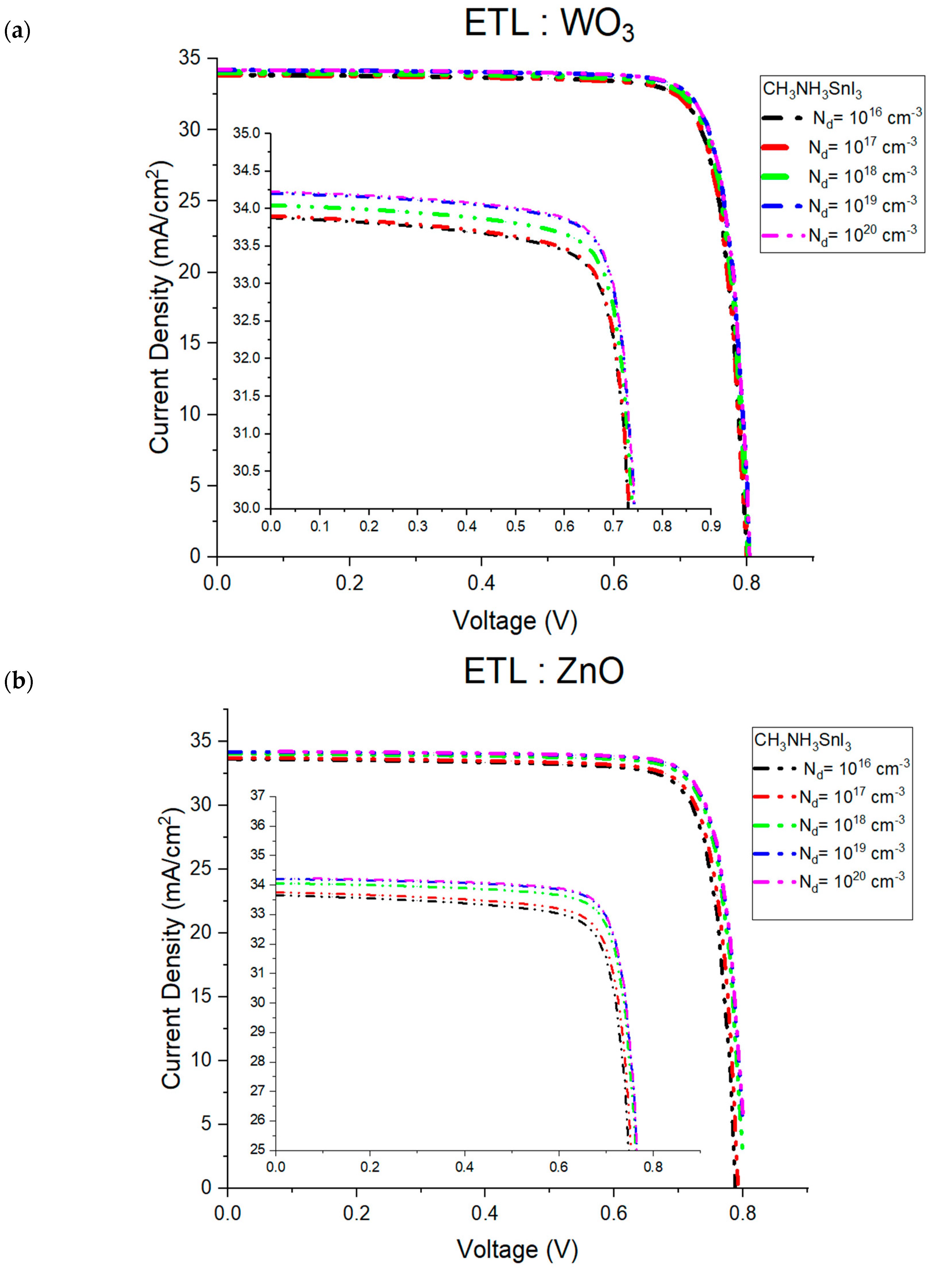
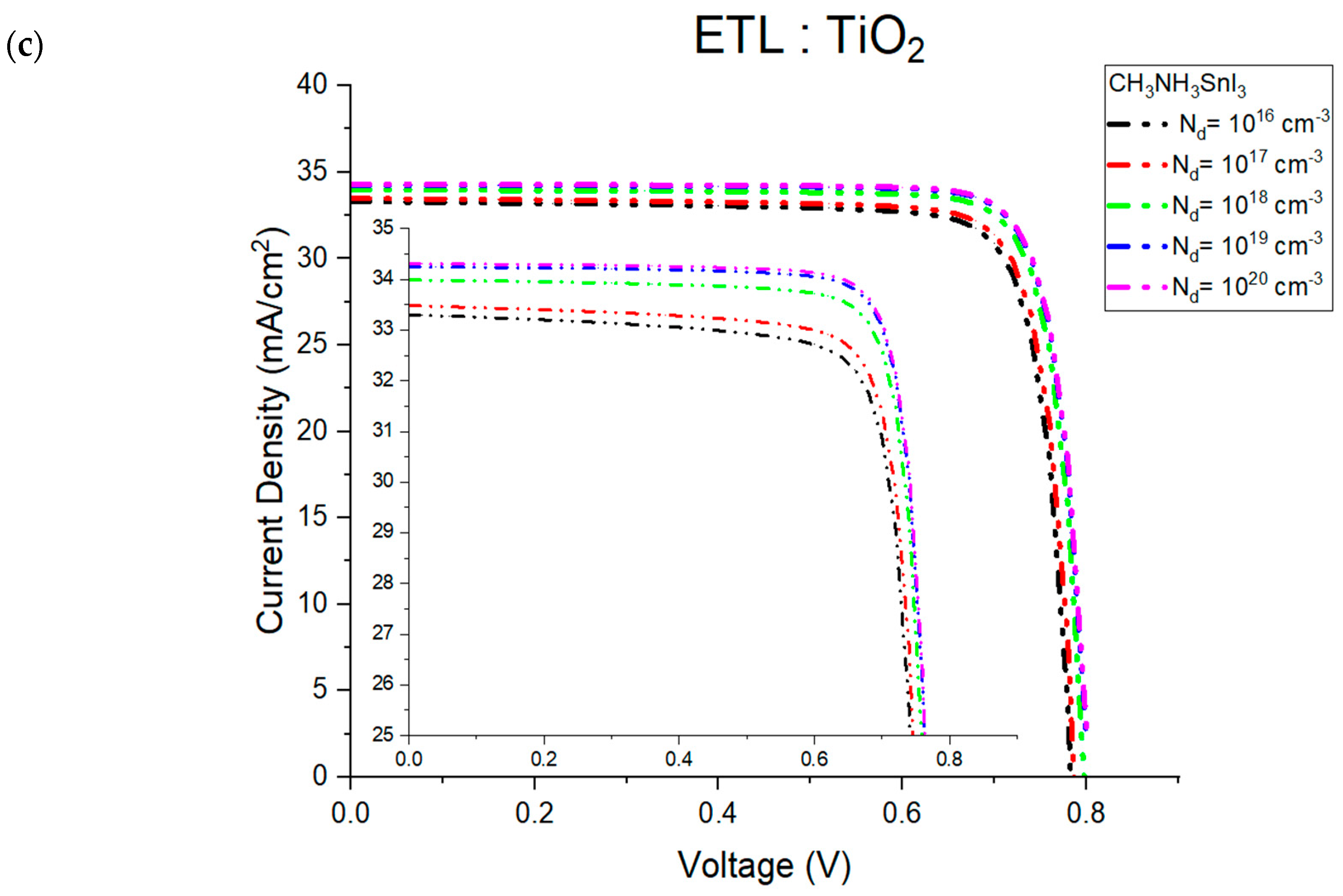
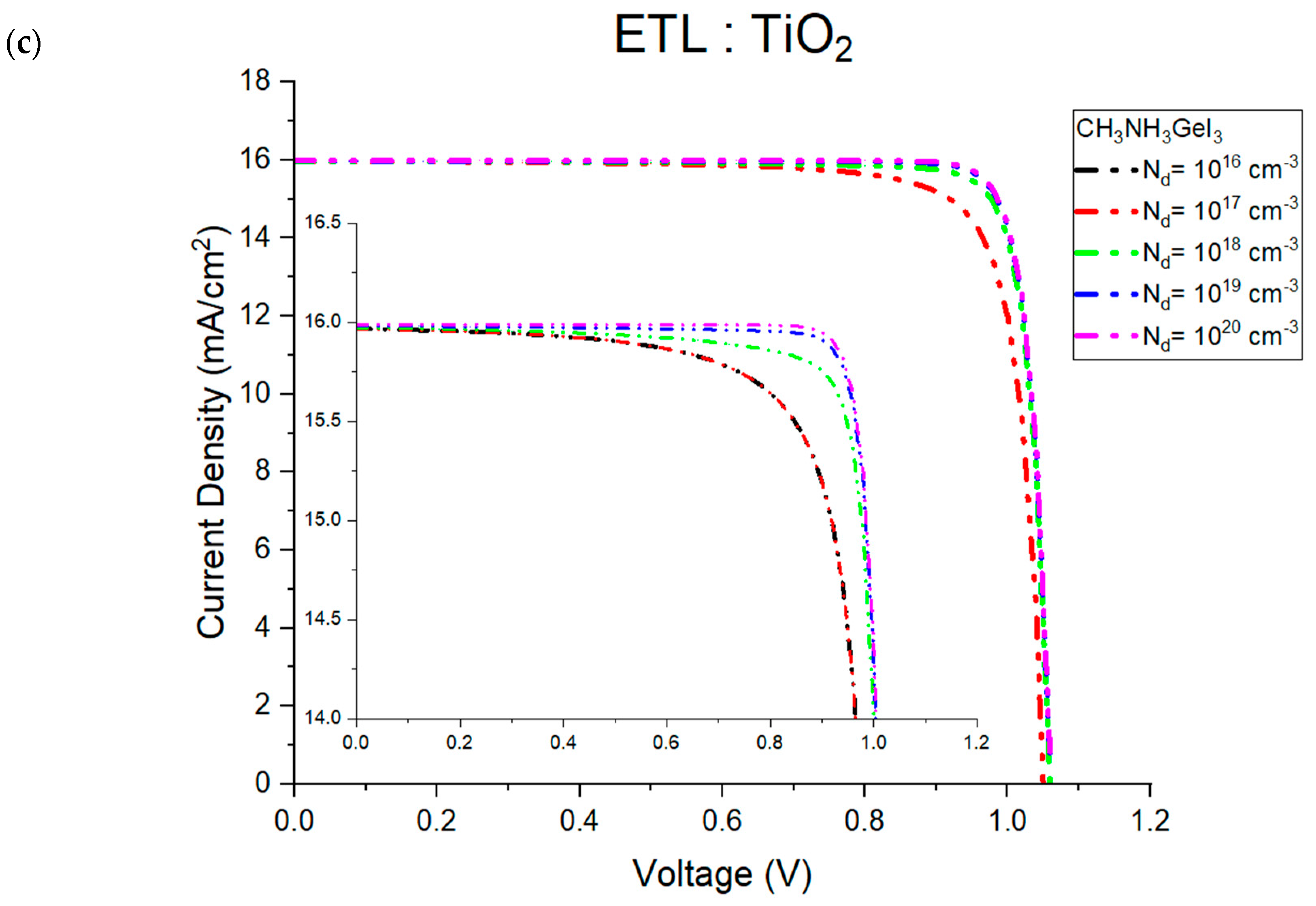
| Parameters | CH3NH3SnI3 (Tin-Based) | CH3NH3GeI3 (Germanium-Based) |
|---|---|---|
| Power Conversion Efficiency (PCE) | 23.19% | 14.83% |
| Open-circuit Voltage (Voc) | ~0.80 V | ~1.06 V |
| Short-circuit Current Density (Jsc) | ~34 mA/cm2 | ~15.7 mA/cm2 |
| Fill Factor (FF) | ~83% | ~88% |
| Bandgap | 1.3 eV | 1.9 eV |
| ETL Material (Optimized) | TiO2 | ZnO |
| ETL Thickness (Optimized) | <50 nm | <30 nm |
| Impact of ETL Material | TiO2 > ZnO > WO3 | ZnO > TiO2 > WO3 |
| ETL Doping Concentration Effect | Minimal effect on PCE | Minimal effect on PCE |
Disclaimer/Publisher’s Note: The statements, opinions and data contained in all publications are solely those of the individual author(s) and contributor(s) and not of MDPI and/or the editor(s). MDPI and/or the editor(s) disclaim responsibility for any injury to people or property resulting from any ideas, methods, instructions or products referred to in the content. |
© 2025 by the authors. Licensee MDPI, Basel, Switzerland. This article is an open access article distributed under the terms and conditions of the Creative Commons Attribution (CC BY) license (https://creativecommons.org/licenses/by/4.0/).
Share and Cite
Al Atem, M.; Makableh, Y. Towards Sustainable Perovskite Solar Cells: Lead-Free High Efficiency Designs with Tin and Germanium. Eng 2025, 6, 38. https://doi.org/10.3390/eng6020038
Al Atem M, Makableh Y. Towards Sustainable Perovskite Solar Cells: Lead-Free High Efficiency Designs with Tin and Germanium. Eng. 2025; 6(2):38. https://doi.org/10.3390/eng6020038
Chicago/Turabian StyleAl Atem, Marc, and Yahia Makableh. 2025. "Towards Sustainable Perovskite Solar Cells: Lead-Free High Efficiency Designs with Tin and Germanium" Eng 6, no. 2: 38. https://doi.org/10.3390/eng6020038
APA StyleAl Atem, M., & Makableh, Y. (2025). Towards Sustainable Perovskite Solar Cells: Lead-Free High Efficiency Designs with Tin and Germanium. Eng, 6(2), 38. https://doi.org/10.3390/eng6020038