Abstract
Tropical climate is characterized by hot temperatures throughout the year. In areas subject to this climate, air conditioning represents an important share of total energy consumption. In some tropical islands, there is no electric grid; in these cases, electricity is often provided by diesel generators. In this study, in order to decarbonize electricity and cooling production and to improve autonomy in a standalone application, a microgrid producing combined cooling and electrical power was proposed. The presented system was composed of photovoltaic panels, a battery, an electrolyzer, a hydrogen tank, a fuel cell, power converters, a heat pump, electrical loads, and an adsorption cooling system. Electricity production and storage were provided by photovoltaic panels and a hydrogen storage system, respectively, while cooling production and storage were achieved using a heat pump and an adsorption cooling system, respectively. The standalone application presented was a single house located in Tahiti, French Polynesia. In this paper, the system as a whole is presented. Then, the interaction between each element is described, and a model of the system is presented. Thirdly, the energy and power management required in order to meet electrical and thermal needs are presented. Then, the results of the control strategy are presented. The results showed that the adsorption cooling system provided 53% of the cooling demand. The use of the adsorption cooling system reduced the needed photovoltaic panel area, the use of the electrolyzer, and the use of the fuel cell by more than 60%, and reduced energy losses by 7% (compared to a classic heat pump) for air conditioning.
1. Introduction
Tropical areas are characterized by hot temperatures throughout the year and high solar radiation due to their position close to the equator. This leads to a high demand for refrigeration and air conditioning. Today, a large part of the energy production in French Polynesia is provided by imported fossil fuels [1]. This creates a dependence on fossil fuels and generates greenhouse gases through combustion in power plants. On the other hand, French Polynesia benefits from a high amount of solar radiation—up to 5.8 kWh/m2/day (vs. 3.4 kWh/m2/day in Paris)—that can be converted into electricity by photovoltaic (PV) panels or into heat by solar thermal collectors [2]. French Polynesia wishes to achieve at least 60% of their electricity production through renewable energies by 2030. In 2018, 31% was produced by hydroelectric power plants and 6% was produced by PV power plants. In order to increase the share of renewables on the electricity mix, the share of PV has to grow, as does storage capacity for the PV output power [1].
Over the past few years, interest in hydrogen has grown, from small-scale off-grid applications to large-scale chemical energy transport. It is the most abundant chemical element in the universe, but on Earth, it is not present in its elementary form. It has to be extracted, as it is present in other molecules, e.g., water, natural gas, and organic matter. Nowadays, more than 90% of hydrogen production comes from natural gas reformation, which causes environmental issues. A promising method of hydrogen production—called green hydrogen—involves water electrolysis using electricity from renewable energy. Water electrolysis converts water into hydrogen and oxygen using an electrical current with a high efficiency (around 70%). Hydrogen is considered an energetic vector, as it can be produced and transported from one geographical place to another in order to supply remote areas.
Fuel cells convert hydrogen and oxygen into electric current, water, and heat by electrochemical reaction. Polymer exchange membrane (PEM) fuel cells are capable of working at low temperatures (below 100 °C). They have an electrical efficiency that exceeds 50%. Their energetic density, low emission rate, low vibration, and noise have allowed for their development and implementation into transportation and stationary applications. They have been proven to have a high efficiency, low emission rate, and economic viability for combined heating and power applications [3,4,5]. The heat produced by PEM fuel cells can be recovered in order to supplement or meet building hot water demand. The authors in [6] studied the degradation of a PEM fuel cell at 80 °C. The authors of [7,8] proved that cogeneration using a hydrogen fuel cell in a standalone household could fulfill both electrical and thermal needs. Their high electrical efficiency and the possibility to recover the heat produced leads to a system efficiency of up to 95% [9].
In stationary applications, it is common to use batteries for self-consumption or grid feed-in to store excess electricity from PV [10]. Battery storage is a mature technology but has an important and inherent loss of capacity and a short lifetime [11]. On the other hand, hydrogen has negligible self-discharge, a high specific energy density (33 kWh/kg) and a low volumetric energy density (150 Wh/L at 60 bars [12]). However, when considering stationary applications, volumetric density is not the primary constraint. Costs are still high and global efficiency of hydrogen storage is relatively low because of the different conversions. Nevertheless, hydrogen is suitable for long-term storage, grid balancing, and on-site renewable energy storage [13]. Hydrogen storage for remote areas could lead to space occupation reduction and, depending on political and economic aspects, could compete with battery storage [14,15].
The processes used to convert the heat of the fuel cell for cooling are typically thermochemical processes, based on reversible thermochemical reactions between a gas and a liquid (absorption) or a gas and a solid (adsorption). Heat pump efficiency is characterized by coefficient of performance (COP). The COP is defined as the ratio between the useful heating or cooling provided and the electrical or thermal energy consumed. For classical heat pumps, the COP is generally above three. For thermochemical heat pumps, the COP is below one. Nevertheless, some studies have focused on system efficiency and considered fuel efficiency in laboratory experiments, leading to system efficiencies of 60% or more [16,17,18]. Fuel cells are used for the trigeneration of electricity, heating, and cooling in hot climates. In [19], the authors used a solid oxide fuel cell (SOFC) with an absorption chiller in an educational building in Tehran. Another group [20] used an SOFC and a two-absorption chiller in an office building in Tokyo. They determined that, for a fully decentralized, SOFC-based energy system, CO2 emissions were reduced by 45% and the cost increase was estimated at 290% compared to a conventional system. In the case of an isolated trigeneration system, the authors of [21] used a solid oxide fuel cell supplied by hydrocarbons to provide on-board electrical, heating, and cooling needs. They found that using an absorption chiller reduced the electrical power needed to cool the air and increased the overall efficiency from 12% (in the case of classical air conditioning) to 43% (with the use of an absorption chiller). Another group of researchers [22] studied the sizing of a cooling/heating and electrical power generation system for standalone applications and the impact of management on the lifetime of the equipment. In this study, cooling was produced by an absorption chiller.
Concerning isolated hybrid PV/hydrogen building application management, the literature proposes many studies on the optimization of sizing, operation cost, or lifetime or a combination of these factors. The authors of [14] conducted a management and sizing optimization study based on particle swarm optimization in order to minimize operation cost with an hourly time step. However, this work considered the possibility of the grid connection. The authors of [23] used fuzzy logic in order to minimize the operation cost and to maximize the lifetime of storage equipment, taking in consideration real equipment with a time step of one hour. The authors of [24] optimized the sizing of energy elements for a standalone application with an hourly time step. Overall, work on standalone hybrid PV/hydrogen management considering cooling demand is insufficiently studied in the literature.
Thus, the main challenge in this study is the use of an electrolyzer and a fuel cell as a heat source for the adsorption cooling system (ACS). The global system consists of a PV power plant, an electrolyzer, a hydrogen tank, a fuel cell, a heat pump, and an ACS that can provide both electrical and cooling needs with no connection to the grid and with no carbon emissions. A battery is connected to a direct current (DC) bus in order to absorb power from and to supply power to the bus, and a hydrogen tank is used to absorb excess PV power (via a water electrolyzer) and to supply power to the bus when there is a PV generation deficit (via a fuel cell stack).
The contributions of this paper are as follows:
- A combined cooling and electrical power management algorithm with a thermal model for a standalone application;
- The integration of an ACS for cooling storage with fuel cell and electrolyzer systems considering existing equipment; and
- An evaluation of the impact of the ACS on performances and sizing.
The paper is organized as follows. In the second section, a system overview is presented, the house is thermally modeled considering the materials and geometry, and the electrical and thermal interactions are presented. The third section presents the electrical and thermal energy modeling and presents the fuel cell and electrolyzer experimental results used in the model. The electric and thermal management is presented in the fourth section, considering real weather and simulated load data with a time step of 10 min. In the fifth section, results over one year are discussed and the impact of the thermal management and the ACS are highlighted. Finally, conclusions are provided.
2. System Overview
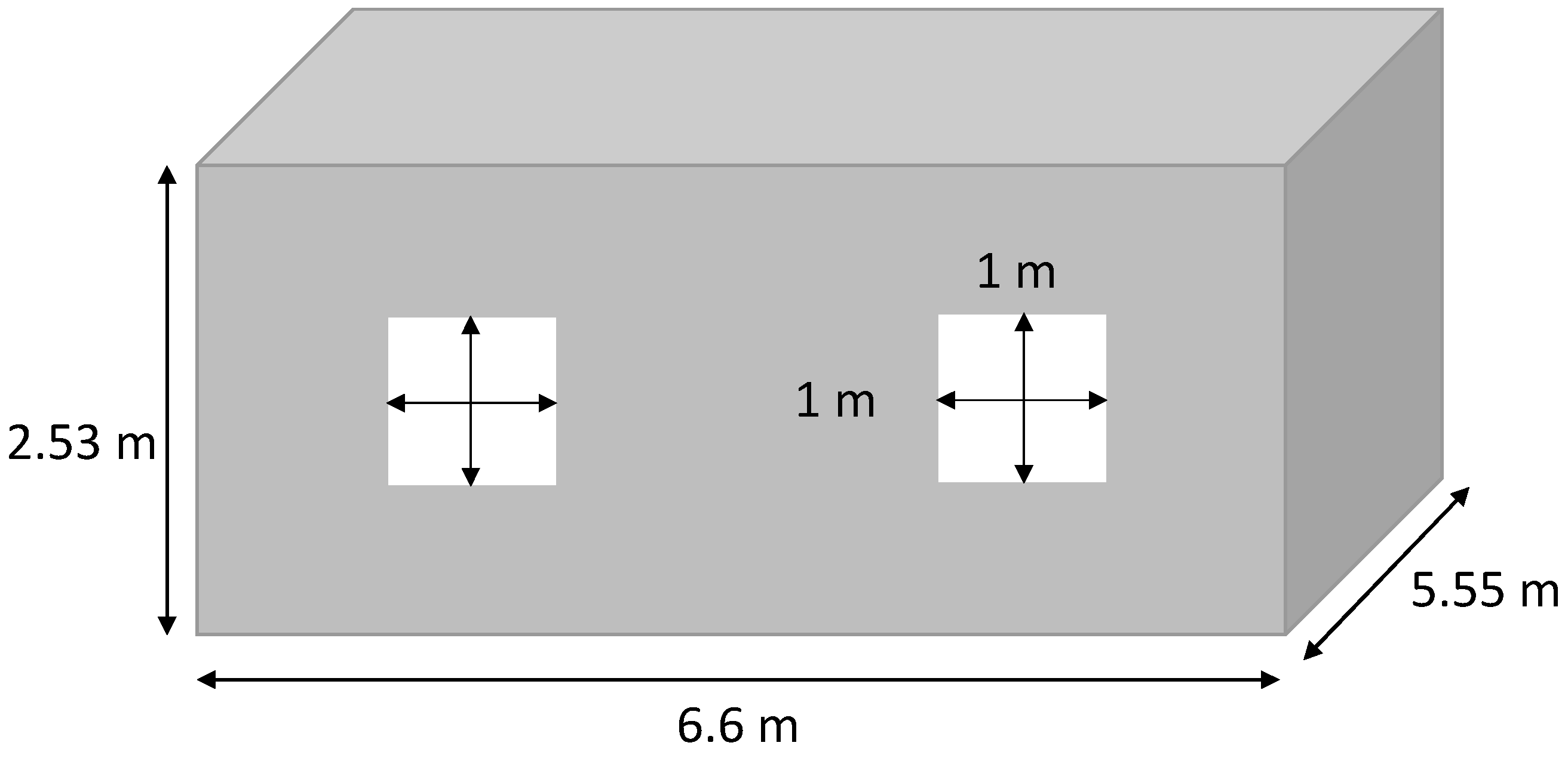
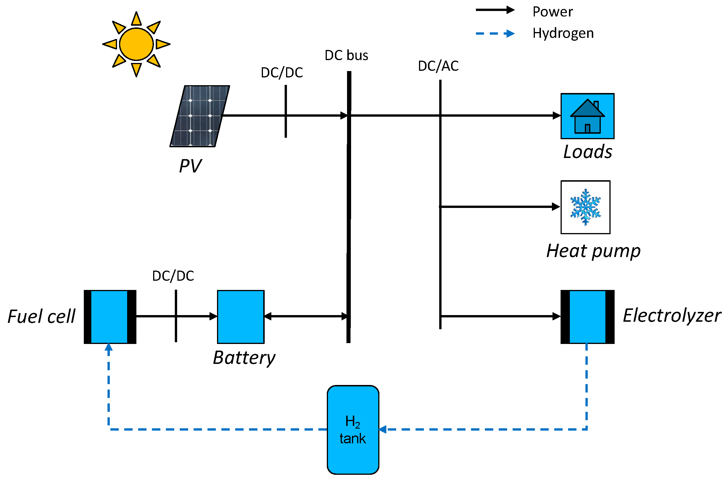
For this study, a common house in the Tahiti region was chosen. This is a low-cost-type house. The four walls, the floor, and the roof are made of a sandwich material of steel and polystyrene. The ceiling is composed of 8 mm PVC layers and a layer of PVC of 2 mm on the ground. The windows are made of a double layer glass with an air layer for insulation. The house characteristics are summarized in Table 1. The materials’ thermal resistance and the geometry of the house are used to determine the equivalent resistance of the house (1), presented in Figure 1. The microgrid is composed of PV panels, power converters, a lithium battery, a PEM electrolyzer, a PEMFC, electrical loads, and an air conditioner (AC). They are all physically connected to a 48 V DC bus, as shown in Figure 2. The use of the DC bus is justified as the PV panels, the battery, and the fuel cells work with direct current. The PV panels are connected to the bus by a converter, and the battery is set at 48 V for the bus voltage. An inverter then converts the direct current to alternative current to supply electricity to the electrical loads, the air conditioning, and the electrolyzer:
with
where i stands for the walls, ceiling, or windows. The ceil thermal resistance is calculated using the addition of the ceil materials resistance and the wall material resistance.

Table 1.
Physical characteristics of the house.
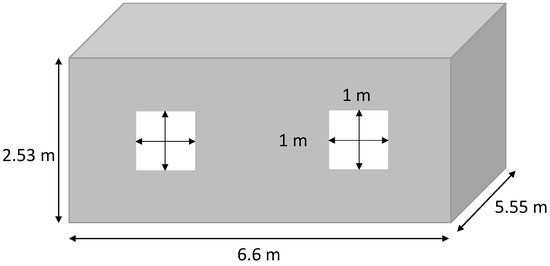
Figure 1.
House dimensions.
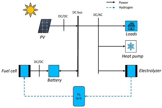
Figure 2.
Microgrid architecture.
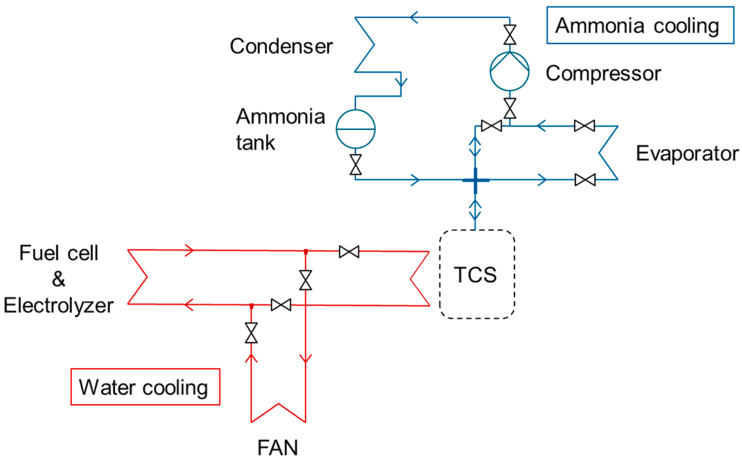
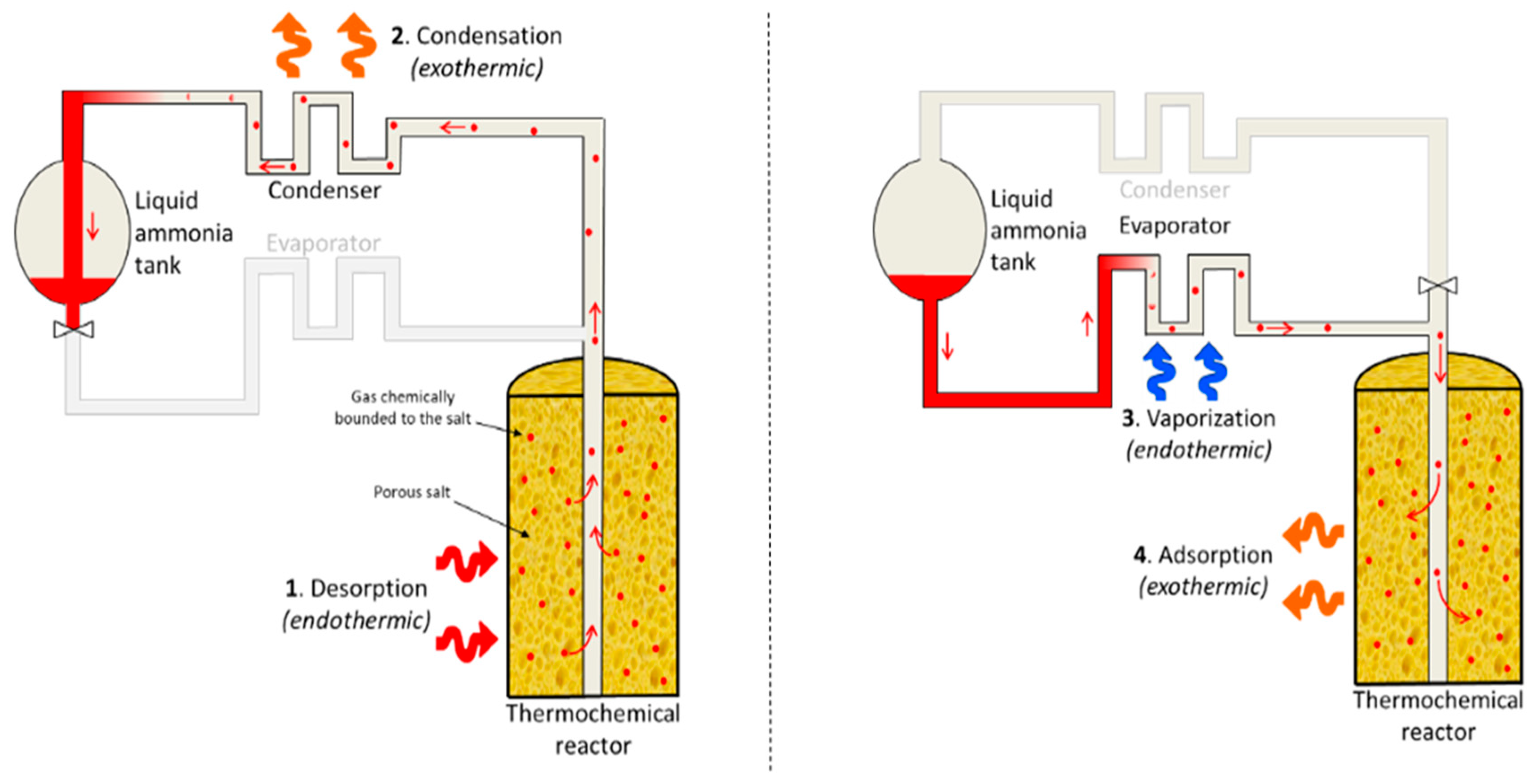
The thermal system is composed of two loops (Figure 3): one water cooling loop for the fuel cell and the electrolyzer and another loop of ammonia cooling for air conditioning and cooling energy storage. The ammonia loop is composed of a compressor, an evaporator, a condenser, an ammonia tank, a thermochemical reactor for cooling storage (TCS on Figure 3), and some valves. The TCS is filled with barium chloride salts on a carbon matrix [25]. During the adsorption reaction, the ammonia gas is fixed on the salt surface and produces heat. The opposite reaction is the desorption and absorbs heat. During the desorption phase, the water loop provides heat to the thermochemical storage in order to desorb the ammonia molecules stored on the surface of the salt. The ammonia gas flows from the TCS to the condenser, where it is liquefied to be stored into the ammonia tank. This is the cooling energy storage operation. A fan on the water loop ensures the cooling of the fuel cell and the electrolyzer in case TCS cannot absorb heat.
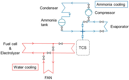
Figure 3.
Cooling system for AC.
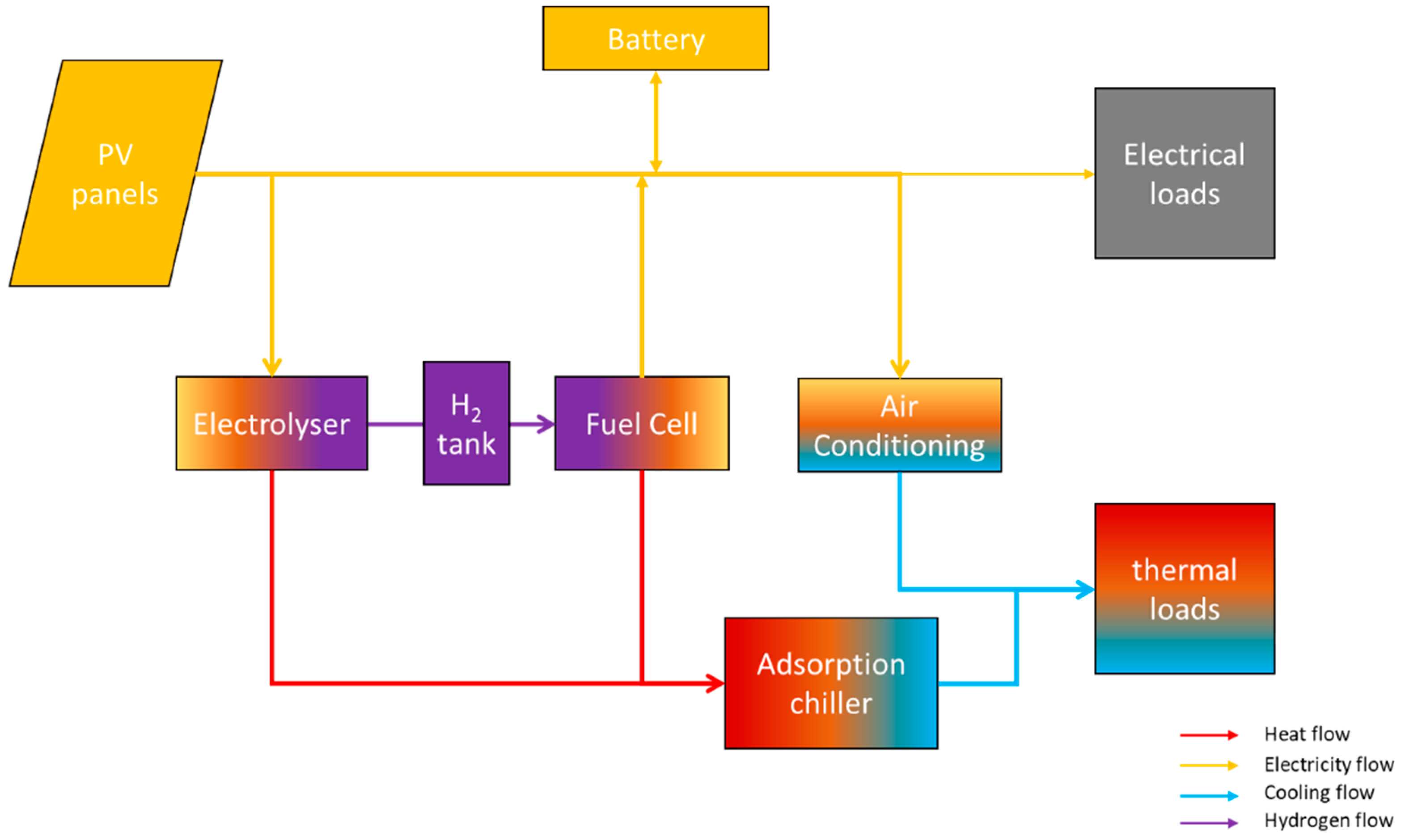
The schematic representation of the entire system is presented in Figure 4.
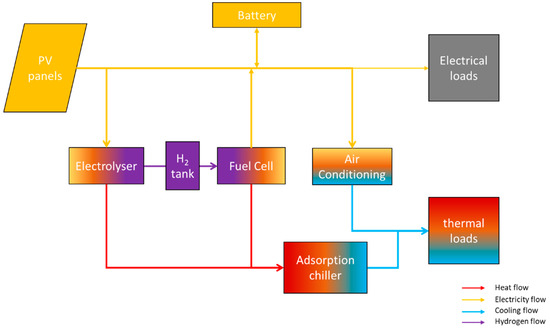
Figure 4.
Overview of the entire system.
3. Energetic Modeling
This section is divided in three parts. The first section deals with the electrical elements, and the second section deals with the thermal components. The third section presents the origin of the values used in the model. The model presented here is focused on the overall system energy and power flows. The constants used for the model are provided in Table 2.

Table 2.
Characteristics of elements.
3.1. Electrical Modeling
The primary source of energy is the sun. The radiant energy of the sun is converted into electricity by PV panels. The PV power produced by the PV panels (Ppv) is proportional to the received solar radiation (Irr) and the panels area (Spv). The PV panel efficiency is noted . On these latitudes, PV panels can be installed horizontally [26]. The output power of the PV panels is present in Equation (3):
The fuel cell is a proton exchange membrane (PEM) fuel cell that works at a constant power Pfc, consuming
Nm3/h of hydrogen. The electrolyzer is a PEM electrolyzer consuming a constant power Pele to produce
Nm3/h of hydrogen. The amount of energy available inside the hydrogen tank can be evaluated by the inside pressure of the tank (PressH2), with R being the perfect gas constant and T being the inside temperature (fixed at 25 °C). At the working pressure (below 60 bars), hydrogen is supposed to be a perfect gas (z = 1.006 at 60 bars and 298 K). Therefore, the perfect gas law can be applied to determine the pressure inside the tank [27] (4):
The hydrogen flow entering (from electrolyzer) or exiting (to fuel cell) the tank is proportional to the electric power consumed (electrolyzer) or produced (fuel cell). In this work, the fuel cell and the electrolyzer work at constant power. The hydrogen flow exiting the tank, , is 0.96 Nm3/h for the fuel cell, and that entering the tank, , is 0.5 Nm3/h for the electrolyzer (see Section 3.3 for experimental results).
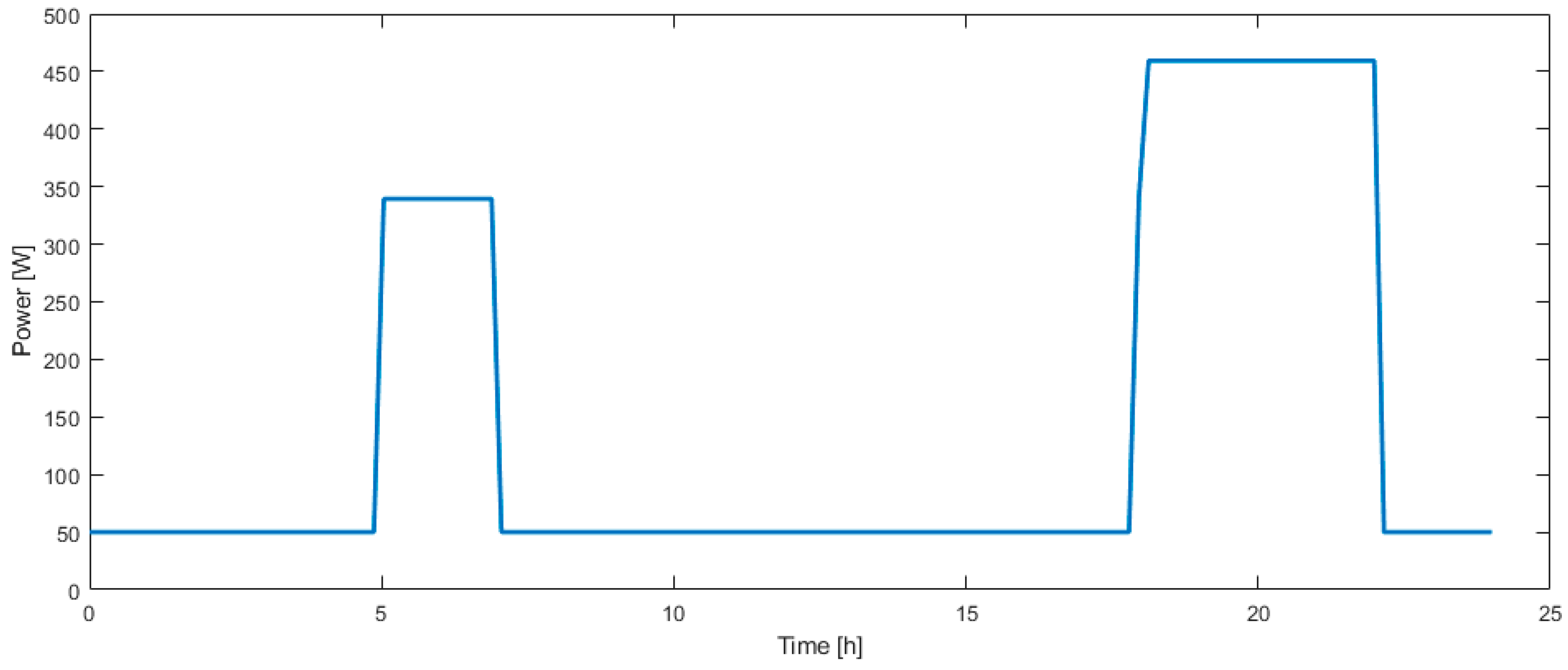
The electric loads considered here are lights, consuming 300 W from 05:00 to 07:00 and from 18:00 to 22:00, and electronic devices consume between 50 W during daytime and 170 W during evening. The corresponding load profile is presented in Figure 5.
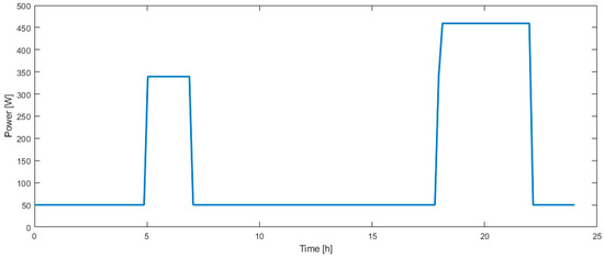
Figure 5.
Electric load profile over one day.
The battery level of energy can be modeled by the SOC, which represents the percentage of available energy compared to the nominal capacity Qn. If the battery is full, SOC = 1, and if it is empty, SOC = 0. Therefore, the SOC is the amount of energy available in the battery and is modeled by Equation (5) where is the power of the battery at the time t:
The heat pump for AC consume electric power Php to produce a cooling power Qcool proportional to the COPhp of the heat pump (6) and works at its nominal power or with excess PV power (7):
Php = min(Php,nom, Ppv,excess)
Finally, the DC bus is the electrical connection between each element of the micro-grid. The amount of power on the bus (Pbus) is the sum of all the power producers minus all of the power consumers at any time (8):
3.2. Thermal Modeling
The heat pump connected to the TCS is presented in Figure 6. This configuration was inspired by [28]. The ammonia tank can be filled using heat processes; as the heat increases the pressure of the thermochemical reactor, the work performed by the compressor can be reduced to zero, or by using surplus PV and the compressor, the reactor can be desorbed. The cooling energy can be stored when there is no cooling demand. Depending on whether the compressor is used and if there is a heat source, the value of the COP changes. Table 3 presents the different values of the COP depending on the conditions of temperature and the work performed by the compressor. The cooling energy is generated by evaporation of ammonia in the evaporator. During the adsorption process, the evaporation of ammonia generates a cooling power Qtcs of 4 kW. The energy balance inside the ammonia tank is as follows (9):
with Qfc and Qele being the heat produced by the fuel cell and the electrolyzer. Qfc and Qele depend on the operation electrical power and the efficiency of the components (10). The fuel cell and electrolyzer efficiency are the mean values that have been experimentally determined on actual systems in our laboratory (see Section 3.3).
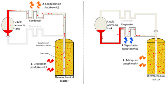
Figure 6.
Adsorption cooling system (ACS). On the left side is the storage phase; on the right side is the cooling production [29].

Table 3.
COP value depending on temperature and compressor work.
The cooling power can also be produced by mechanical vapor compression (MVC)—the most common method used to produce cooling power—as seen in Equation (6).
As long as the room temperature is not in equilibrium with that outside, a thermal transfer occurs between the outside and the inside through the walls and is dependent on the temperature difference and the thermal resistance of the house (depending on the geometry and the materials, determined in Table 1 (11):
In tropical areas, as the incidence of sun radiation is important because of the poor thermal efficiency of local houses, it is important to consider it for thermal modelling of these houses. The amount of heat received is proportional to the solar radiation, the contact surface, and an empirical coefficient . It is assumed that only half of the house is exposed to the sun. The proposed model (12) is an empirical model that is considered as sufficient for our intended application.
The house indoor temperature variation is the sum of three heat flows: the heat losses, the heat received by solar radiation, and the heat subtracted by the air conditioner (13). In this model, no air change rate is considered.
3.3. Fuel Cell and Electrolyzer Test Results
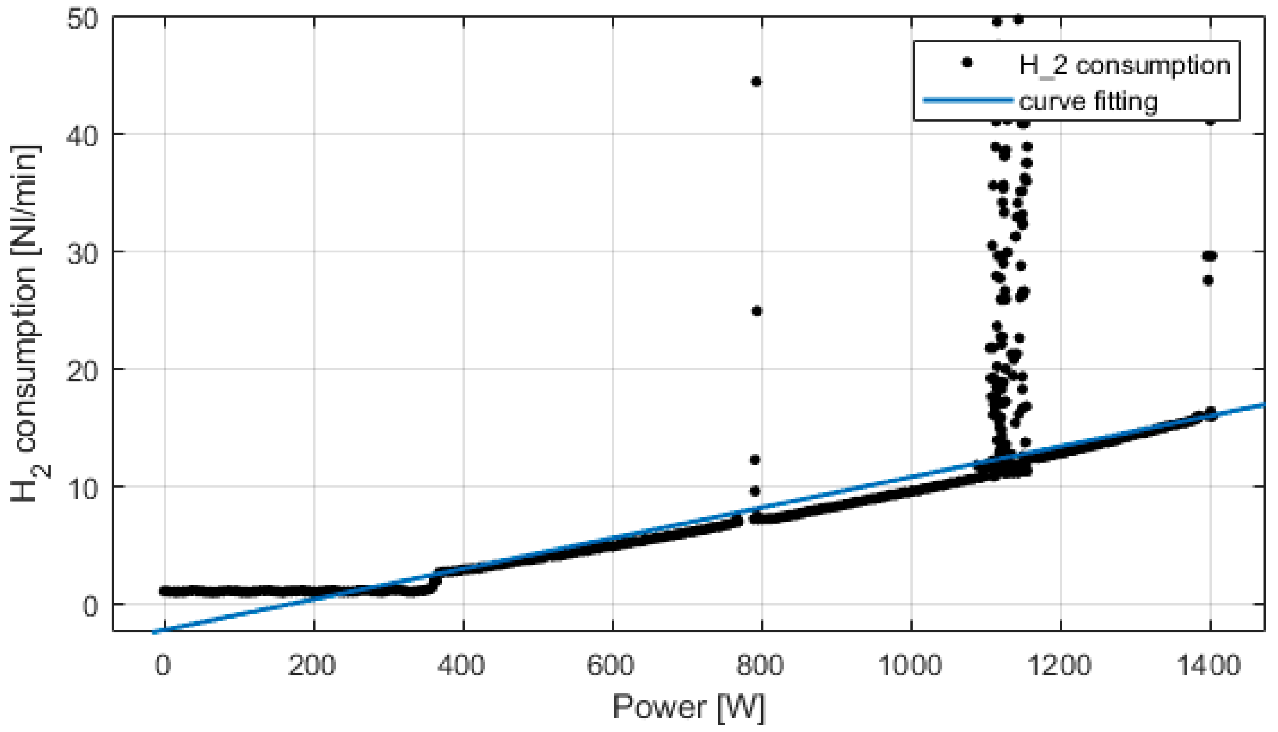
Experimental tests have been conducted on the fuel cell and electrolyzer system. The PEM fuel cell is rated at 1.5 kW, water cooled. The PEM electrolyzer works at 2.1 kW, producing 0.5 Nm3/h, water cooled. Figure 7 presents the fuel cell hydrogen consumption versus the power produced. Up to 300 W, the fuel cell is in IDLE phase; then from 300 W to 1400 W, the hydrogen consumption is proportional to the power produced. At 1400 W, the hydrogen consumption is 16 NL/min, which corresponds to 0.96 Nm3/h. The peaks on the figure are due to normal hydrogen purges of the fuel cell that lasts less than 1s.
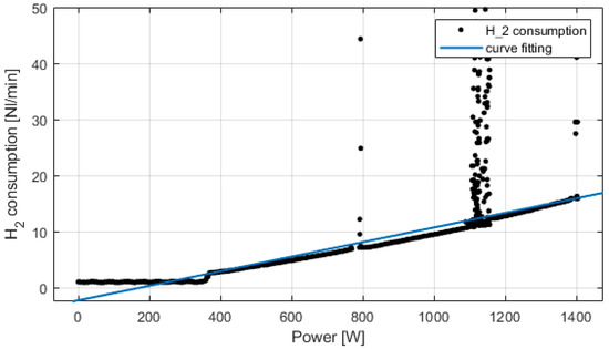
Figure 7.
Experimental fuel cell’s consumption and curve fitting.
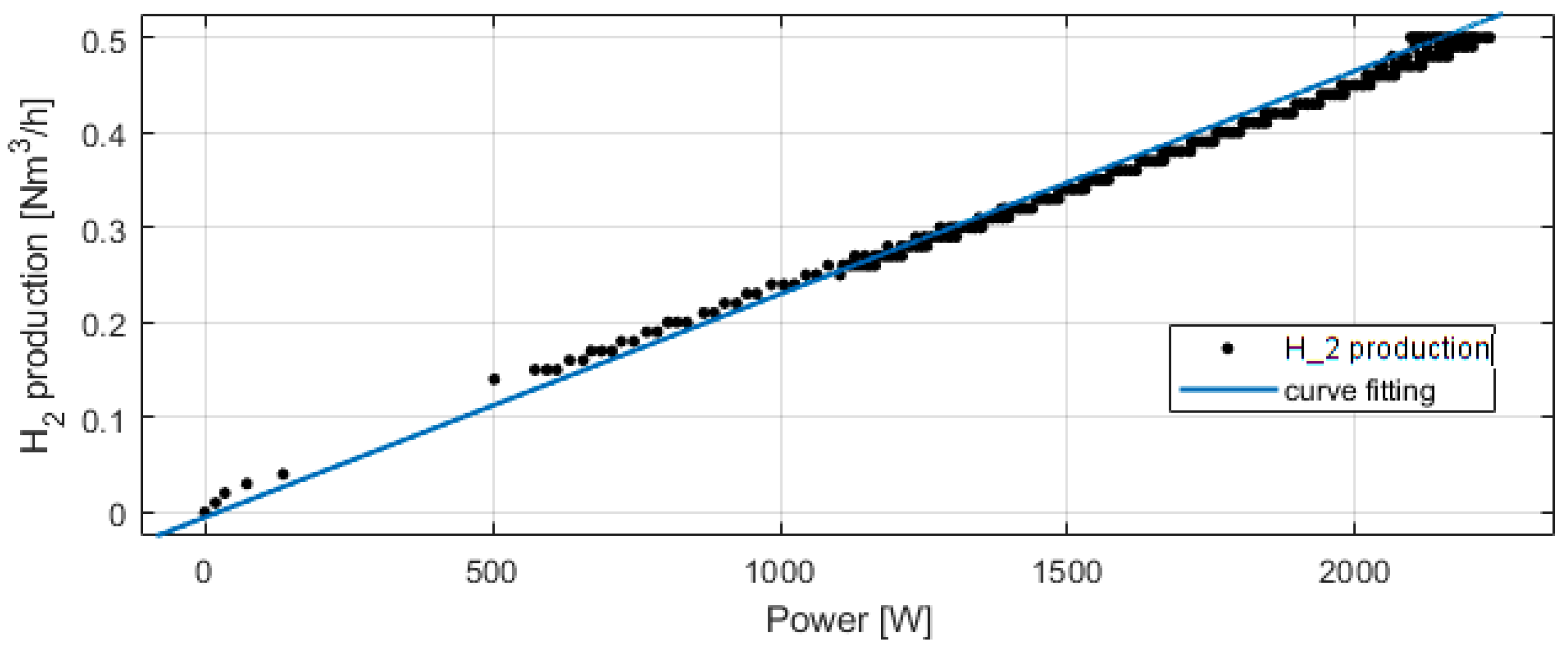
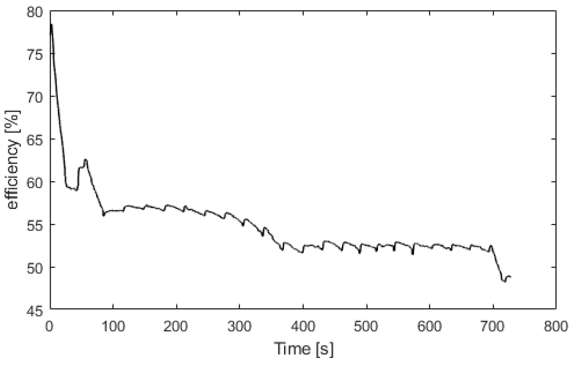
Figure 8 presents the electrolyzer hydrogen production versus the power consumed. The produced hydrogen flow is proportional to the power consumed, and at 2100 W, the hydrogen production flow is 0.5 Nm3/h. For Figure 9, Figure 10, Figure 11 and Figure 12, the fuel cell and the electrolyzer were started and their nominal working point were set, i.e., 60 A and 71 A, respectively. Figure 9 presents the fuel cell efficiency defined as the ratio between the lower heating value of hydrogen consumed and the electrical power produced. After the startup phase of 100 s, the fuel cell efficiency is constant at 55%, and after 400 s, at its nominal working point, the efficiency is constant at 54%.
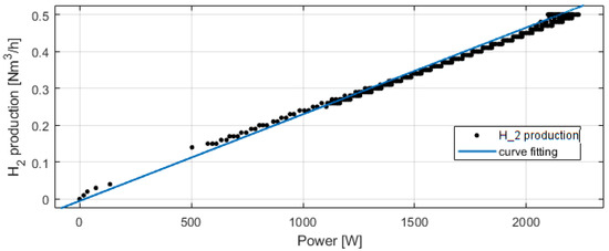
Figure 8.
Experimental electrolyzer hydrogen production and curve fitting.
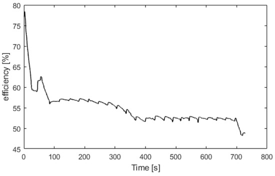
Figure 9.
Fuel cell efficiency versus time.
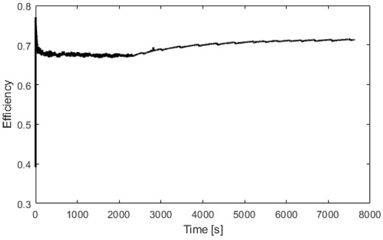
Figure 10.
Electrolyzer efficiency versus time.
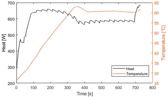
Figure 11.
Fuel cell heat production and temperature.
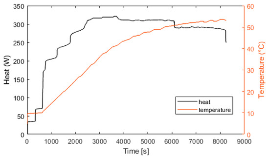
Figure 12.
Electrolyzer heat production and temperature.
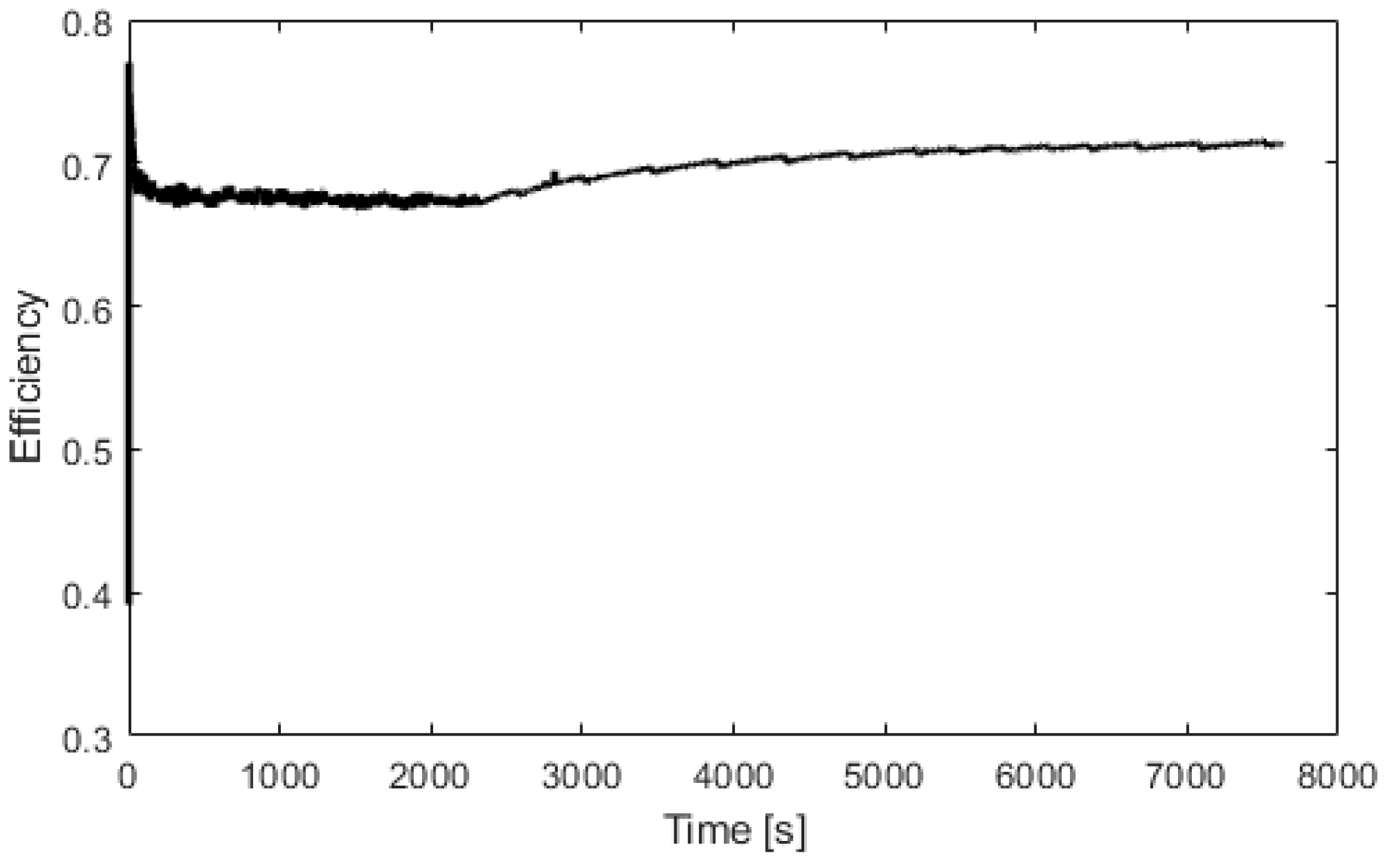
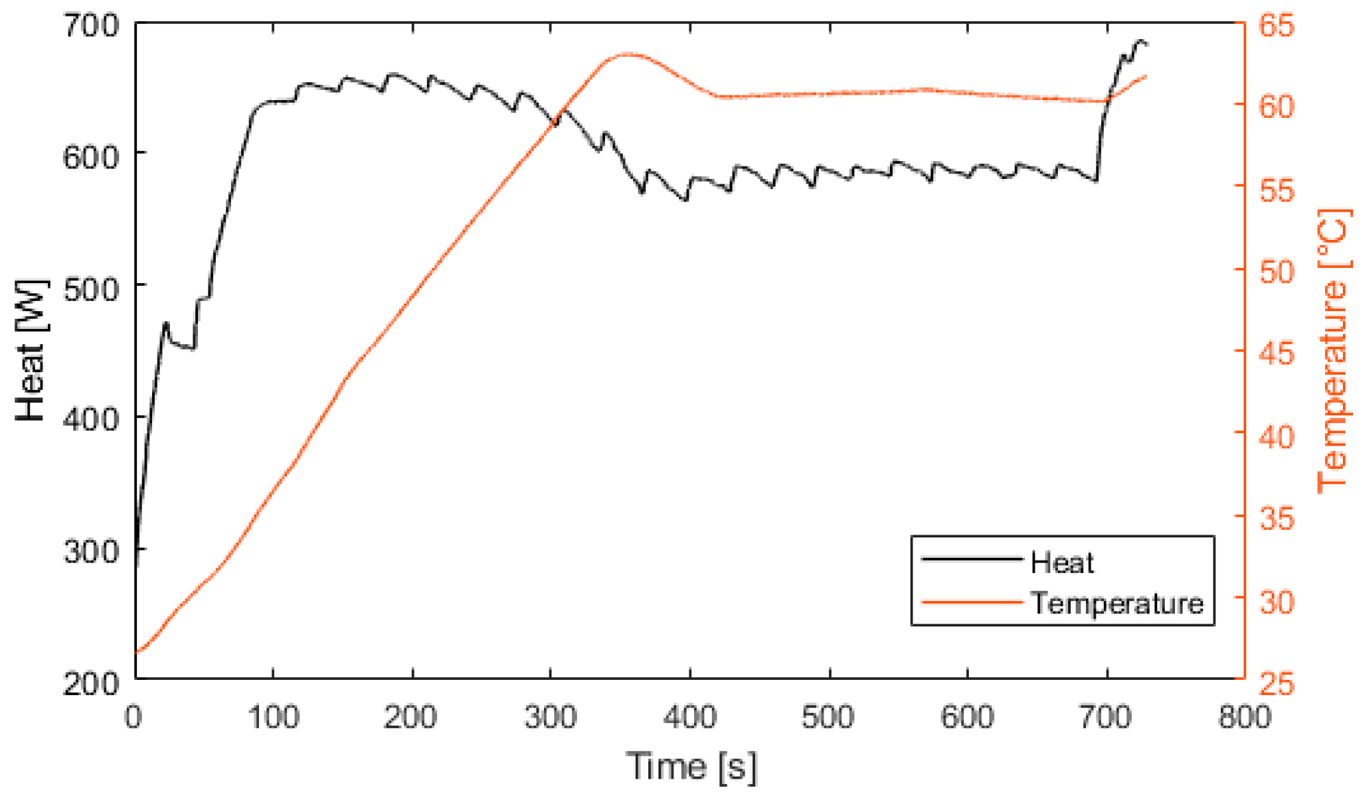
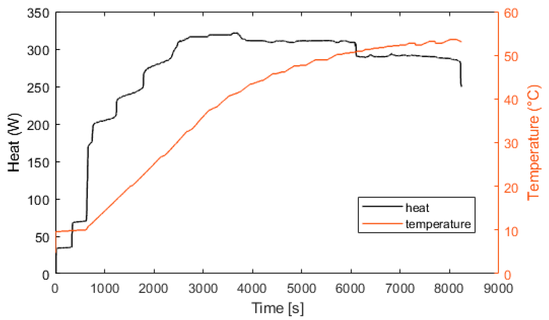
Figure 10 represents the efficiency of the electrolyzer, defined as the ratio between the hydrogen energy produced and the electrical energy consumed. The thermal efficiency is considered constant with a value of 70%. Figure 11 presents the heat exchanged by the fuel cell. After 100 s, the fuel cell produces 600 W of heat. At 400 s, the fuel cell is at its nominal temperature of 60 °C. Figure 12 presents the heat exchanged by the electrolyzer. These data correspond to a cold start with an ambient temperature of 10 °C. Then, after a startup phase of 600 s, the heat exchanged is constant at 300 W.
4. Electrical and Thermal Management
The power management has to match, at any time, the electrical and thermal demands. The dispatching of the electrical power between each element for electrical continuity is presented in first in the following section. The thermal management of the house, depending on the inside temperature and the occupancy of the building, is then presented in the subsequent section.
4.1. Electrical Power Management
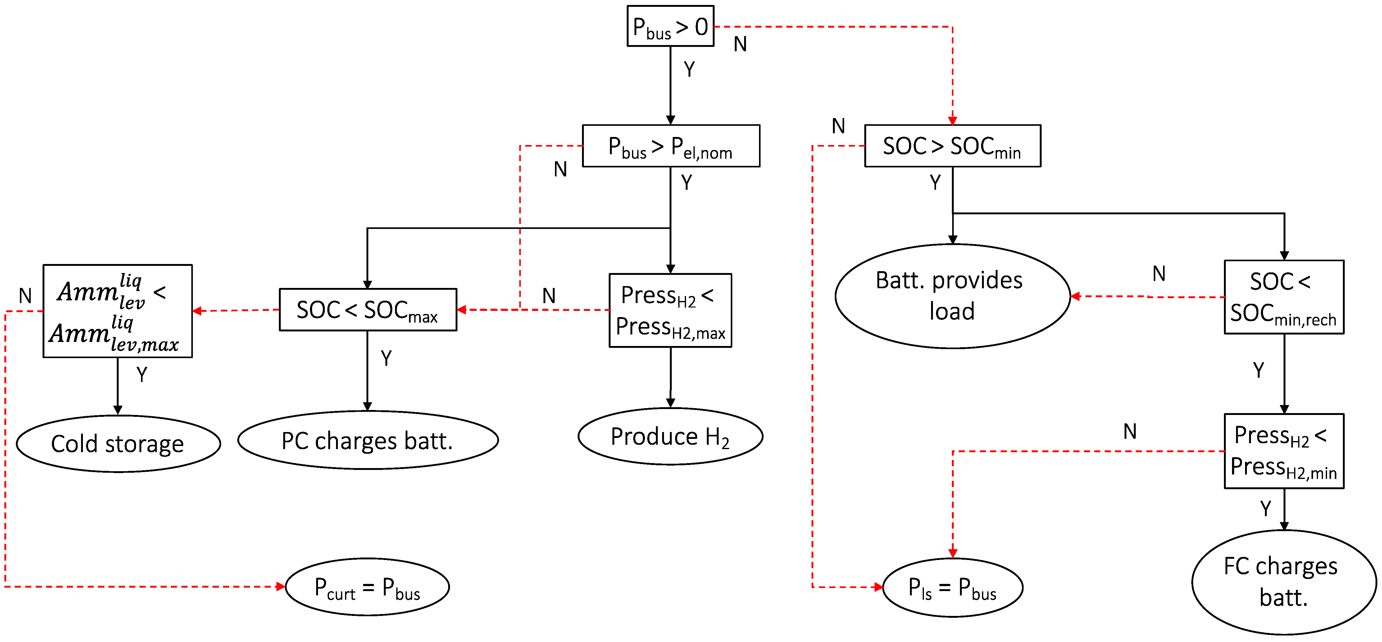
The power management strategy can be summarized as follows. The primary source of energy (PV power) provides the electrical needs. The electrical load (the demand) is satisfied first. Then, surplus energy, if any, is used in order of priority as follows: first, to charge the electrochemical battery (if the SOC <100%), then to switch on the electrolyzer for hydrogen production (if the hydrogen tank is not full), and to switch on the compressor to remove gas from the thermochemical reactor (storage phase of adsorption process for deferred cooling production). If all the storage components are full, then the power is curtailed (Pcurt).
In case the power demand is higher than the PV power, the battery provides the power needed. The fuel cell ensures the SOC is maintained above a minimum capacity (SOCmin,rech) if the hydrogen tank is not empty. If both the hydrogen tank and the battery are empty, then the power demand cannot be met and the load must be reduced or shedded (Pls), but as size of the energetic system is constructed as optimally as possible, this situation should never occur.
Figure 13 summarizes the algorithm for managing power flow in a flowchart.
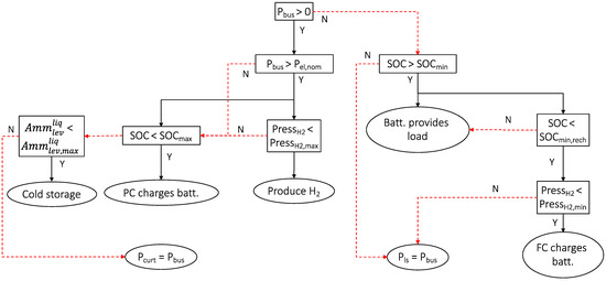
Figure 13.
Electrical power management.
4.2. Thermal Management
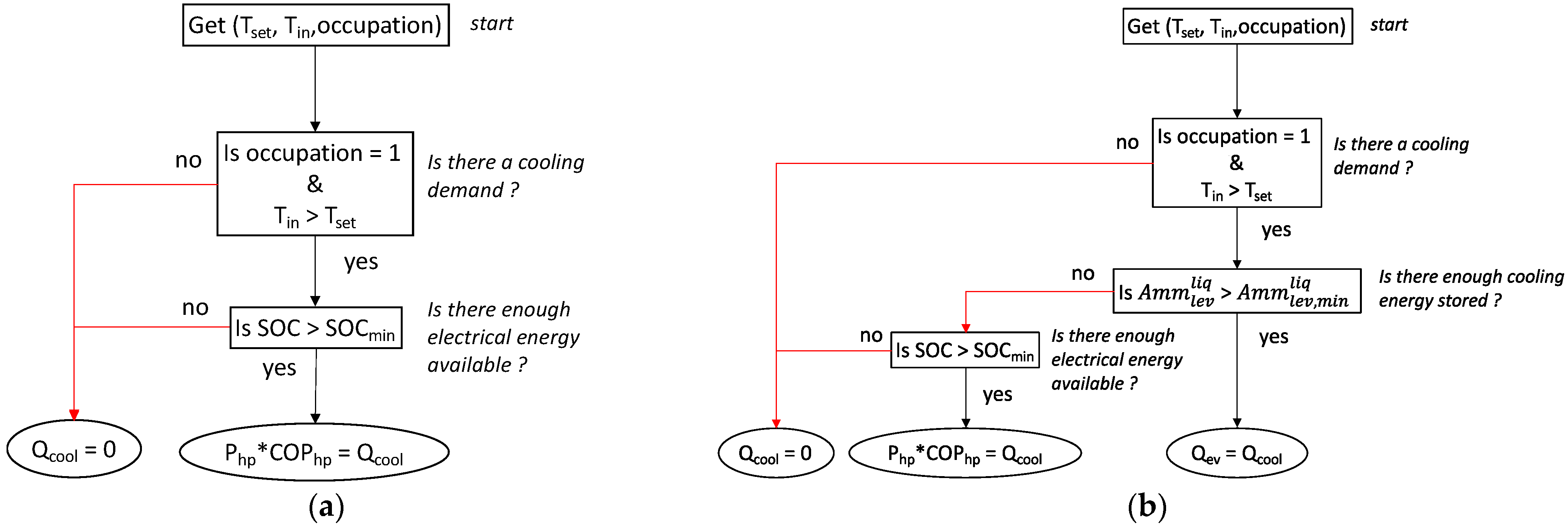
If the room is occupied (occupancy = 1) and the inside temperature is above the set temperature (Tset), the cooling demand must be satisfied. In our simulation, occupancy is defined from 6 p.m. to 8 a.m. It must be noted that, at these times of the day in such tropical areas, there is no solar energy available.
To satisfy the cooling demand and to highlight the interest of the TCS, two scenarios were applied. In the first strategy, cooling was produced by the heat pump at normal operation, with the compressor being supplied by the batteries (Figure 14a). The second scenario implies the use of the liquid ammonia previously stored in a tank that provides cooling by adsorption (through the evaporator) as long as the tank is not empty. If the tank is empty, the first scenario is used (Figure 14b).
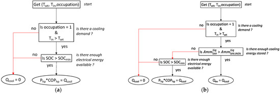
Figure 14.
(a) Thermal management without TCS; (b) thermal management with TCS.
5. Results
The results are presented for a one-year simulation. The simulation was run in MATLAB with a time step of 10 min. The working time and the number of starts of the fuel cell and the electrolyzer were recorded. Indeed, for these two components, multiple start–stop cycles were one of the major issues regarding their durability. The number of cycles of the battery was counted. The ratio of electrical energy consumed by the heat pump compared to the total electrical consumption (electronics load plus air conditioning) and the ratio of cooling produced by the ACS compared to the total cooling produced were also recorded. To show the impact of the ACS, a comparison was made between a thermal management with and without the ACS. The impact of the thermal management and the set temperature are also presented. Finally, the impact of the TCS size was studied.
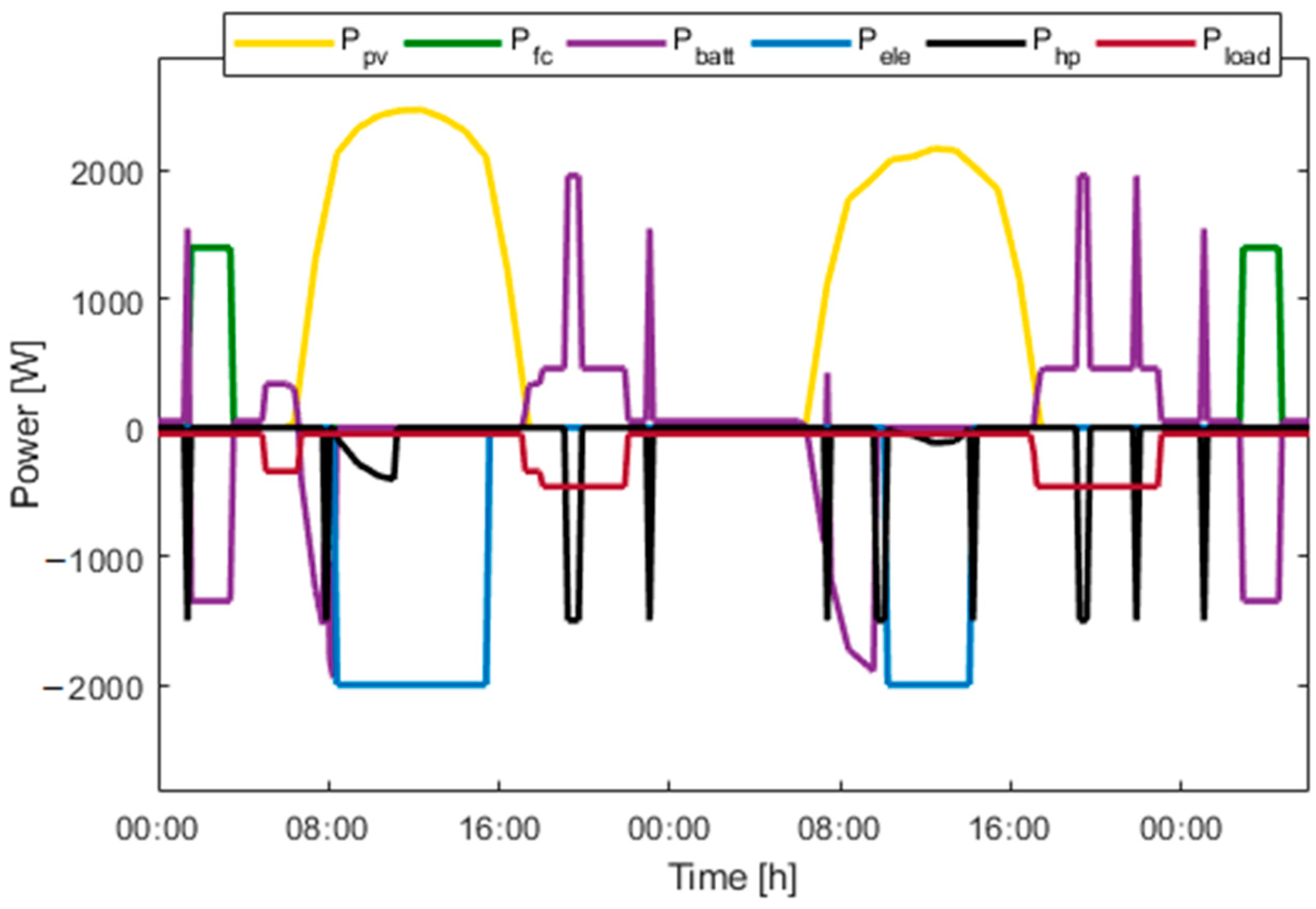
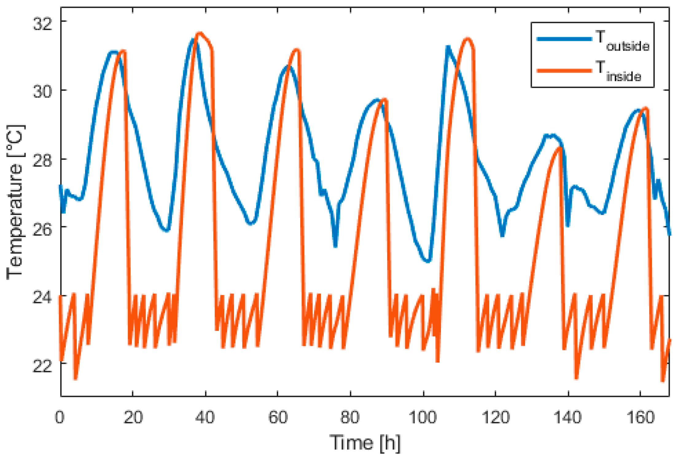
Figure 15, Figure 16, Figure 17, Figure 18, Figure 19 and Figure 20 presents the results for a PV area of 12 m2 and a setpoint temperature of 24 °C. Figure 15 presents the power of each component on the DC bus. Two consecutive days were chosen. This figure shows that the fuel cell produces electric power during periods of nighttime and the electrolyzer work during high PV-production hours. The heat pump stores cooling energy during the day and produces cooling energy during the night. During the evening and nighttime, the electrical load is supplied mainly by the battery. Figure 16 presents the temperature inside the building (orange) and the outside temperature (blue). It can be seen that the proposed thermal management is able to reduce the inside temperature in less than one hour. During the night, the inside temperature is maintained below 24 °C.
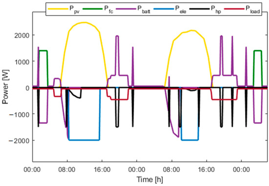
Figure 15.
Power over two consecutive days.
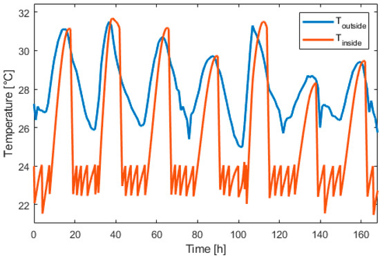
Figure 16.
Inside and outside temperature evolution over one week.
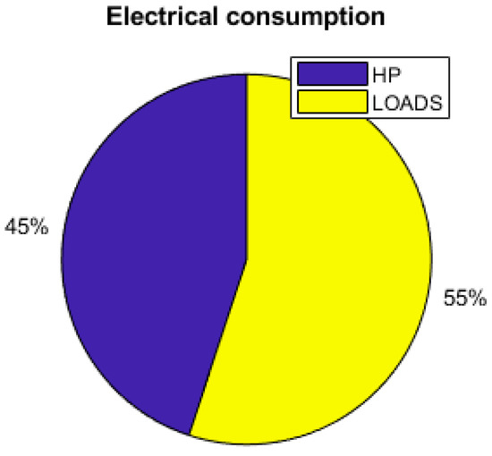
Figure 17.
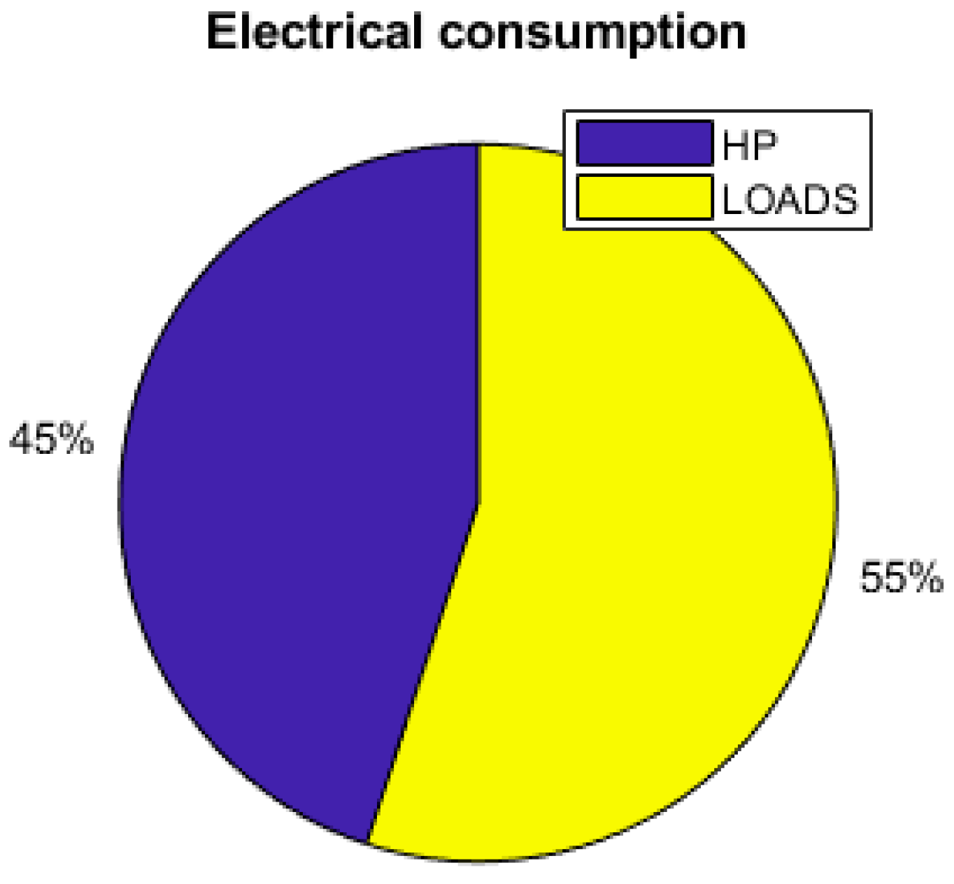
Electrical consumption.
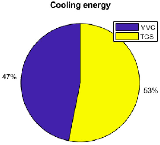
Figure 18.
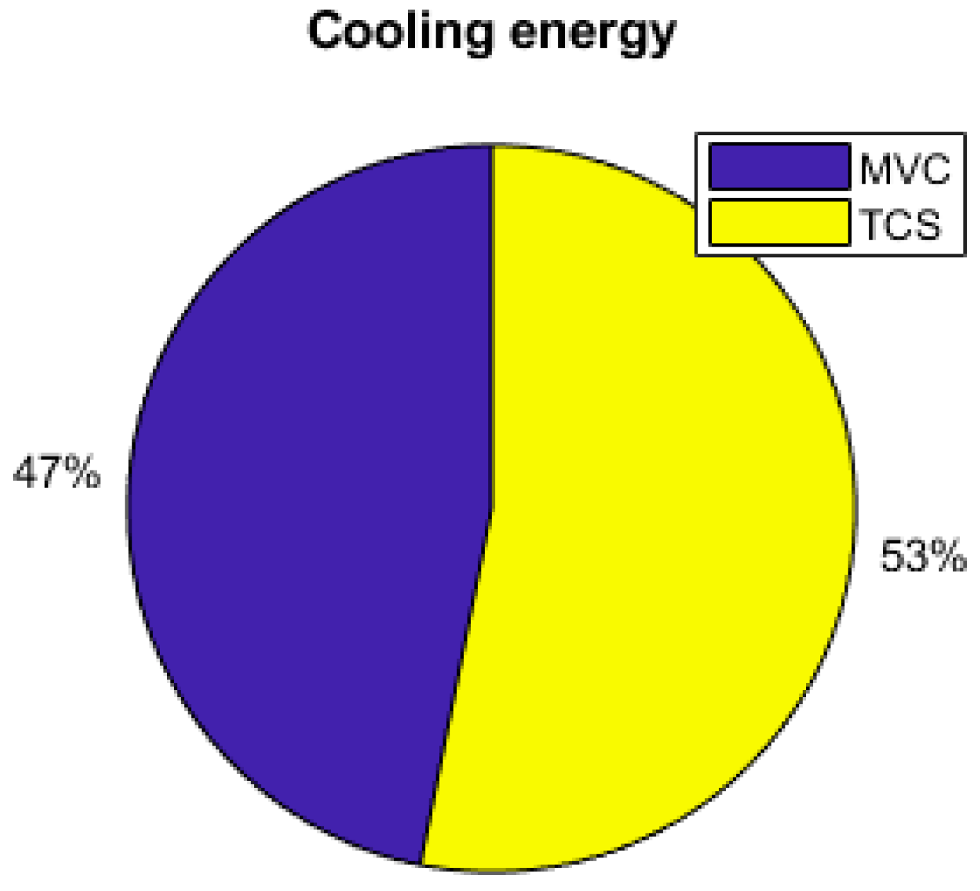
Cooling production contributions.
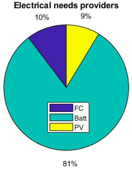
Figure 19.
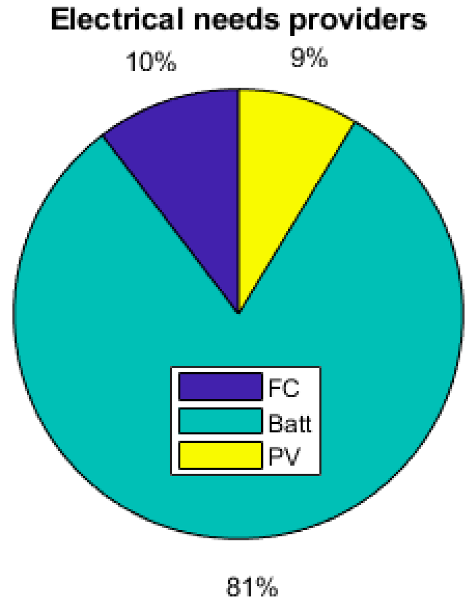
Breakdown of electrical providers.
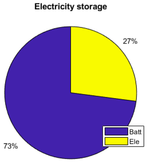
Figure 20.
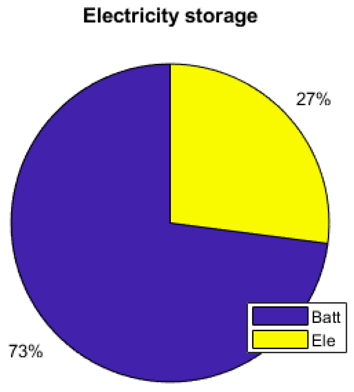
PV excess storage.
Figure 17 shows that the thermal demand represents 45% of the yearly total electrical energy consumption. The set temperature also has an impact on the energy consumption and the sizing of the components. Reducing the set temperature from 26 °C to 24 °C requires increasing the PV area by 14%, as shown is Table 4. Table 4 shows that the thermal management and the set temperature have a large impact on the utility of the hydrogen storage. With no thermal demand, the fuel cell and the electrolyzer are barely used, but in contrast with a thermal management and a relatively low temperature, they are shown to be useful, as the working time of the fuel cell and the electrolyzer are multiplied by more than 3.

Table 4.
Impact of the set temperature.
As the energy consumption is separated from the PV production, storage elements are the main contributors to the electrical supply of the demand. The total yearly electrical consumption is 2300 kWh. The battery provides 81% of the load (electronics and AC), which represents 1309 kWh; the FC provides 10% of the needs, which represents 168 kWh; and the PV provides 9% (140 kWh), as presented in Figure 19. Figure 20 shows that the PV excess production is stored at 27% by the electrolyzer and at 73% by the battery and that 51.7% of the PV production is lost when all storage elements are full. Figure 18 presents the cooling production contributions. The total amount of cooling produced is 3149 kWh. The ACS produces 53% of the cooling, and the heat pump provides the remaining 47%. A mean of 4.6 kWh/day of cooling is produced by the ACS for a total of 8.6 kWh/day of cooling.
Table 5 presents the results of the impact of the use of the ACS for cooling storage compared to classical cooling production (without storage). The ACS reduces the working time of the fuel cell (Tfc) and the electrolyzer (Tele) by 60% and 62%, respectively, and decreases the number of starts of the fuel cell by 57% and the number of starts of the electrolyzer by 54%. The minimum PV area required for installation is reduced by 14%. The number of cycles of the battery is reduced by 11% with the use of the ACS. System efficiency is increased, as 7% of the curtailed PV production had been saved. The heat pump compressor is a more often used with the ACS because the compressor is used to store cooling when there is no cooling demand, this explains the high contribution of the PV in Figure 20. Each time the room is occupied, and the inside temperature is above 26 °C, it is considered that the thermal demand is not provided, and then, the time Thot is recorded. The thermal comfort (Thot) is slightly degraded because the power cooling of the ACS (4 kW) is inferior to the cooling power of the classical air conditioning (6.3 kW), but this could be neglected as it represents 20 min per day.

Table 5.
Comparison of strategy with and without TCS for a set temperature of 24 °C.
The impact of the TCS size is presented in Table 6. As the TCS capacity increases, the PV production loss reduces as the PV area and the ratio of cooling produced by the TCS increase consequently. With 15 kWh of cooling capacity, the TCS can provide 96% of the cooling demand.

Table 6.
Impact of the TCS size for a set temperature of 24 °C.
The results showed that, dynamically, with the equipment considered and the energy management applied, the electrical and cooling demand are provided with no load shedding and that, daily, thermal comfort is ensured for less than one hour per day, with the temperature inside the building often considered too hot. A comparison of cooling with or without the use of the ACS showed that the ACS, providing 53% of the cooling demand, reduces the working time of the fuel cell and electrolyzer by more than 60% and the number of cycles of the battery by 11%.
6. Conclusions and Perspectives
In this study, we proposed a microgrid architecture and a power management strategy for electrical and cooling supply to a standalone house in a tropical area. The proposed strategy considers the weather conditions, the thermal and the electrical demand, the occupancy of the house, and the energy level inside the storage components. The results have shown that the ACS can provide 53% of the cooling demand and reduces the fuel cell and electrolyzer working time by more than 60%. This could lead to a lifetime of improvements. The ACS also increased the system efficiency, as it reduces the PV energy lost by 7%. The results also showed the importance of thermal load consideration on the sizing and the energy consumption as it represents 45% of the electrical consumption. In this situation, the hydrogen storage system proved its usefulness as the working time of the fuel cell and the electrolyzer increased with thermal energy demand. In order to improve the cooling ratio and to reduce the electric consumption, the amount of heat recovered could be increased by the addition of a solar heat collector or an increase in the water-cooling circuit temperature. As the ACS has an impact on the use of both the fuel cell and the electrolyzer, further studies should be conducted on the lifetime impact on these elements. A technoeconomic analysis of the system could also be conducted as future work, but since some equipment are currently under development, an estimate of the cost is hard to determine at this time. Further studies could also be conducted on the impact of load size and profile, other strategies and control methods can be designed, and the lifetime impact can be further evaluated.
Author Contributions
Conceptualization, H.L.; project administration, P.O.; supervision, R.R., S.J., P.O., and D.H.; writing—original draft, H.L.; writing—review and editing, R.R., S.J., P.O., and D.H. All authors have read and agreed to the published version of the manuscript.
Funding
This research was funded by the French Research Agency under the RECIF project (contract ANR-18-CE05-0043), by the EIPHI Graduate School (contract ANR-17-EURE-0002), and by the Region Bourgogne Franche-Comté.
Data Availability Statement
This study used private datas.
Acknowledgments
This work has been supported by the French Research Agency under the RECIF project (contract ANR-18-CE05-0043), by the EIPHI Graduate School (contract ANR-17-EURE-0002), and by the Region Bourgogne Franche-Comté. The authors thank Antoine PERRIGOT of the PROMES laboratory and Franco Nicolas FERRUCCI of the GEPASUD laboratory for the thermochemical process description as well as Franck LUCAS for the data simulation.
Conflicts of Interest
The authors declare no conflicts of interest.
References
- Transition énergétique. Available online: https://www.edt.pf/transition-energetique-innovation (accessed on 26 November 2020).
- Hopuare, M.; Lucas-Svay, L.; Ortega, P.; Lucas, F.; Laurent, V. Assessing Solar resource and photovoltaic production in tahiti from ground-based measurements. E3S Web Conf. 2019, 107, 01003. [Google Scholar] [CrossRef]
- Elmer, T.; Worall, M.; Wu, S.; Riffat, S.B. Fuel cell technology for domestic built environment applications: State of-the-art review. Renew. Sustain. Energy Rev. 2015, 42, 913–931. [Google Scholar] [CrossRef]
- Di Marcoberardino, G.; Manzolini, G.; Guignard, C.; Magaud, V. Optimization of a micro-CHP system based on polymer electrolyte membrane fuel cell and membrane reactor from economic and life cycle assessment point of view. Chem. Eng. Process. Process Intensif. 2018, 131, 70–83. [Google Scholar] [CrossRef]
- Briguglio, N.; Ferraro, M.; Brunaccini, G.; Antonucci, V. Evaluation of a Low Temperature Fuel Cell System for Residential CHP. Int. J. Hydrogen Energy 2011, 36, 8023–8029. [Google Scholar] [CrossRef]
- Pahon, E.; Morando, S.; Petrone, R.; Péra, M.-C.; Hissel, D.; Yousfi-Steiner, N.; Jemei, S.; Gouriveau, R.; Chamagne, D.; Moçotéguy, P.; et al. Long-term tests duration reduction for PEMFC μ-CHP application. Int. J. Hydrogen Energy 2017, 42, 1527–1533. [Google Scholar] [CrossRef]
- Assaf, J.; Shabani, B. Economic analysis and assessment of a standalone solar-hydrogen combined heat and power system integrated with solar-thermal collectors. Int. J. Hydrogen Energy 2016, 41, 18389–18404. [Google Scholar] [CrossRef]
- Lacko, R.; Drobnič, B.; Mori, M.; Sekavčnik, M.; Vidmar, M. Stand-alone renewable combined heat and power system with hydrogen technologies for household application. Energy 2014, 77, 164–170. [Google Scholar] [CrossRef]
- Lambert, H.; Roche, R.; Jemeï, S.; Ortega, P.; Hissel, D. Cogénération, Trigénération et Gestion de l’énergie Des Systèmes Stationnaires à Base de Piles à Combustible. Etat de l’art 2020. [Google Scholar] [CrossRef]
- Bortolini, M.; Gamberi, M.; Graziani, A. Technical and economic design of photovoltaic and battery energy storage system. Energy Convers. Manag. 2014, 86, 81–92. [Google Scholar] [CrossRef]
- Sloop, S.E.; Kerr, J.B.; Kinoshita, K. The Role of Li-Ion Battery Electrolyte Reactivity in Performance Decline and Self-Discharge. J. Power Sources 2003, 119–121, 330–337. [Google Scholar] [CrossRef]
- Züttel, A.; Remhof, A.; Borgschulte, A.; Friedrichs, O. Hydrogen: The future energy carrier. Philos. Trans. R. Soc. Math. Phys. Eng. Sci. 2010, 368, 3329–3342. [Google Scholar] [CrossRef]
- Zhang, Y.; Campana, P.E.; Lundblad, A.; Yan, J. Comparative study of hydrogen storage and battery storage in grid connected photovoltaic system: Storage sizing and rule-based operation. Appl. Energy 2017, 201, 397–411. [Google Scholar] [CrossRef]
- Avril, S.; Arnaud, G.; Florentin, A.; Vinard, M. Multi-objective optimization of batteries and hydrogen storage technologies for remote photovoltaic systems. Energy 2010, 35, 5300–5308. [Google Scholar] [CrossRef]
- Gray, E.M.A.; Webb, C.J.; Andrews, J.; Shabani, B.; Tsai, P.J.; Chan, S.L.I. Hydrogen Storage for off-grid power supply. Int. J. Hydrogen Energy 2011, 36, 654–663. [Google Scholar] [CrossRef]
- Nguyen, H.Q.; Shabani, B. Proton exchange membrane fuel cells heat recovery opportunities for combined heating/cooling and power applications. Energy Convers. Manag. 2019, 204, 112328. [Google Scholar] [CrossRef]
- Oro, M.V.; de Oliveira, R.G.; Bazzo, E. An Integrated solution for waste heat recovery from fuel cells applied to adsorption systems. Appl. Therm. Eng. 2018, 136, 747–754. [Google Scholar] [CrossRef]
- Palomba, V.; Ferraro, M.; Frazzica, A.; Vasta, S.; Sergi, F.; Antonucci, V. Dynamic simulation of a multi-generation system, for electric and cooling energy provision, employing a SOFC cogenerator and an adsorption chiller. Energy Procedia 2017, 143, 416–423. [Google Scholar] [CrossRef]
- Mehrpooya, M.; Sadeghzadeh, M.; Rahimi, A.; Pouriman, M. Technical performance analysis of a combined cooling heating and power (CCHP) system based on solid oxide fuel cell (SOFC) technology—A building application. Energy Convers. Manag. 2019, 198, 111767. [Google Scholar] [CrossRef]
- Weber, C.; Maréchal, F.; Favrat, D.; Kraines, S. Optimization of an SOFC-based decentralized polygeneration system for providing energy services in an office-building in Tōkyō. Appl. Therm. Eng. 2006, 26, 1409–1419. [Google Scholar] [CrossRef]
- Tse, L.K.C.; Wilkins, S.; McGlashan, N.; Urban, B.; Martinez-Botas, R. Solid oxide fuel cell/gas turbine trigeneration system for marine applications. J. Power Sources 2011, 196, 3149–3162. [Google Scholar] [CrossRef]
- Li, B.; Roche, R.; Paire, D.; Miraoui, A. Sizing of a stand-alone microgrid considering electric power, cooling/heating, hydrogen loads and hydrogen storage degradation. Appl. Energy 2017, 205, 1244–1259. [Google Scholar] [CrossRef]
- García, P.; Torreglosa, J.P.; Fernández, L.M.; Jurado, F. Optimal energy management system for stand-alone wind turbine/photovoltaic/hydrogen/battery hybrid system with supervisory control based on fuzzy logic. Int. J. Hydrogen Energy 2013, 38, 14146–14158. [Google Scholar] [CrossRef]
- Marino, C.; Nucara, A.; Panzera, M.F.; Pietrafesa, M.; Varano, V. Energetic and economic analysis of a stand alone photovoltaic system with hydrogen storage. Renew. Energy 2019, 142, 316–329. [Google Scholar] [CrossRef]
- Ferrucci, F.; Stitou, D.; Ortega, P.; Lucas, F. Mechanical compressor-driven thermochemical storage for cooling applications in tropical insular regions. Energy Procedia 2017, 142, 3415–3420. [Google Scholar] [CrossRef]
- Perrigot, A.; Perier-Muzet, M.; Ortega, P.; Stitou, D. Technical economic analysis of pv-driven electricity and cold cogeneration systems using particle swarm optimization algorithm. Energy 2020, 211, 119009. [Google Scholar] [CrossRef]
- Attemene, N.S.; Agbli, K.S.; Fofana, S.; Hissel, D. Optimal sizing of a wind, fuel cell, electrolyzer, battery and supercapacitor system for off-grid applications. Int. J. Hydrogen Energy 2020, 45, 5512–5525. [Google Scholar] [CrossRef]
- Ferrucci, F.; Stitou, D.; Ortega, P.; Lucas, F. Mechanical compressor-driven thermochemical storage for cooling applications in tropical insular regions. Concept and efficiency analysis. Appl. Energy 2018, 219, 240–255. [Google Scholar] [CrossRef]
- Projet RECIF – Site Web Du Projet RECIF. Available online: https://projetrecif.promes.cnrs.fr/ (accessed on 27 November 2020).
- Ferrucci, F. PV-Driven Vapor Compression Cycle Integrating Asolid-Gas Thermochemical Storage for Cooling Applications; Université de Polynésie Française: Faaa, French Polynesia, 2020. [Google Scholar]
- Oliveira, R.G.; Wang, R.Z.; Kiplagat, J.K.; Wang, C.Y. Novel composite sorbent for resorption systems and for chemisorption air conditioners driven by low generation temperature. Renew. Energy 2009, 34, 2757–2764. [Google Scholar] [CrossRef]
Publisher’s Note: MDPI stays neutral with regard to jurisdictional claims in published maps and institutional affiliations. |
© 2021 by the authors. Licensee MDPI, Basel, Switzerland. This article is an open access article distributed under the terms and conditions of the Creative Commons Attribution (CC BY) license (https://creativecommons.org/licenses/by/4.0/).

