Proceeding Paper

Energy Efficiency Ratio Analysis of Half Cycle Air-Conditioners Using Liquified Petroleum Gas †

Faculty of Mechanical Engineering, GIK Institute of Engineering Sciences and Technology, Topi 23460, Pakistan
*
Author to whom correspondence should be addressed.
Presented at the 1st International Conference on Energy, Power and Environment, Gujrat, Pakistan, 11–12 November 2021.
Eng. Proc. 2021, 12(1), 5; https://doi.org/10.3390/engproc2021012005
Published: 20 December 2021
(This article belongs to the Proceedings of The 1st International Conference on Energy, Power and Environment)

Abstract

:
Alternative fuels have proven to be an effective means of reducing the environmental impact of road transportation. On the other hand, the increasing use of air conditioning has declined the fuel economy of passenger vehicles. Half-cycle air conditioning systems (HCACSs) can address this concern of the declining fuel economy by using the fuel as a refrigerant. One of the candidates to be considered as refrigerants in HCACSs is liquefied petroleum gas (LPG). Under various conditions, LPG in the liquid state is injected into the evaporator of an HCACS. At the end of the evaporation process, LPG vapors can be directed for the combustion taking place in devices such as generators, automobiles, and cooking stoves. The present study investigates the performance of three in-housed manufactured evaporators having staggered and/or aligned tube arrangements with variable tube sizes, numbers of fins, fin spacings, and fin materials. As a refrigerant, LPG, having 65% propane and 35% butane, was passed through three evaporators. The energy efficiency ratios (EERs) were indirectly measured for evaporative pressures of 132, 168, and 201 kPa, with mass flow rates of 0.6, 0.75, and 0.9 g/s, respectively, when the fan speed interacting with the evaporators was varied. The results revealed that the aligned configuration with the same tube and fin material performed better even at low fan speeds.

1. Introduction

Half-cycle air-conditioning systems (HCACSs) do not require compressors and condensers to provide air conditioning, because the working fluid before going through the systems has already been liquefied at high pressure. The refrigerant must have a low saturation temperature at the pressure at which it is liquefied, because it has to absorb latent heat from the air flowing over the evaporator while passing through the systems [1]. Compressed natural gas (CNG) and liquefied petroleum gas (LPG) are the utmost common fuels used in spark ignition (SI) engines [2,3]. LPG is a blend of hydrocarbons such as propane, butane, or isobutene and can act as a potential refrigerant for use in a HCACS. The cooling effect-produced refrigerant LPG depends on the formation of LPG [4]. The evaporator is the heart of the HCACS, since it exchanges heat between the conditioned air and the refrigerant. The rate of heat transfer may differ for different flow rates of air under similar conditions. No evaporators were designed and developed previously for HCACSs using LPG as a refrigerant. The researchers mainly used evaporators designed for vapor compression cycles [5]. The cooling effect of LPG is determined by its rate of flow, evaporative pressures (EVPs) in evaporators, and LPG composition, which differ by country and climate [6]. The present research was conducted to probe the cooling characteristics of LPG accessible in Pakistan with a composition of 65 percent propane and 35 percent butane in terms of the energy efficiency ratio (EER) [5]. The EER can effectively calculate the performance of HCACSs. The EER is defined as the ratio of the cooling produced by refrigerant evaporation in an evaporator to the total power input required to produce cooling. An in-house developed experimental setup has been employed for investigating the characteristics of LPG in terms of cooling for various evaporators that have been designed.

2. Materials and Methods

2.1. Methodology and Setup Design

To calculate the EERs for various evaporators, cooling effects produced had to be calculated. For this purpose, the HCACS experimental setup schematic is shown in Figure 1. Liquid LPG, which is widely available on the market, was stored in a cylinder at high pressures of up to 413 kPa. To obtain the liquid LPG, the cylinder was kept inverted during experiments. The cylinder with a flow control valve directed the liquid LPG towards the system’s evaporator. The liquid LPG interacted with the air flowing over it, absorbing its latent heat; as a result, the LPG vaporized in the evaporator, and the interacting air cooled.
The cooling effect produced by LPG was determined using the equation as follows:
Q = m ˙   ( h 1 h 2 ) ,
where m ˙ denotes the rate at which the mass of air flows, and the energy contents of air at the evaporator’s inlet and exit are denoted by h 1 and h 2 , respectively. Both enthalpy values on the psychometric chart were calculated using the respective temperatures and air relative humidity values at the input and output of the evaporator, as well as ambient pressure. The fan that was used for the experiments had a 3A rated current, which was powered by a 12 V battery for all fan speeds.

2.2. Description of Evaporators

The following is a list of the evaporator configurations that were used in the experiments with the respective specifications given in Table 1.

3. Design of Experiments

The expansion valve maintained the rate of flow of liquid LPG from the inverted cylinder. The EVP and the rate of flow of LPG were directly related to the load applied after the evaporation process. Depending on the set of the EVP and the flow rate, the LPG vapors were consumed in stoves, 110 cc LPG-converted engines, or both. The test rig was synchronized, such that if the flow rate was 0.9 g/s, the EVP was 201 kPa and LPG vapors were consumed in two stoves and a running LPG engine. If LPG was consumed in the engine and one stove, the flow rate and the EVP was 0.75 g/s and 168 kPa, respectively. Similarly, if two stoves were in use, then LPG rate of flow was 0.6 g/s and the EVP was 132 kPa. These experimental conditions are denoted as condition 1, condition 2, and condition 3, respectively. The EER of each evaporator was investigated at all these three conditions and at 5 different fan speeds. Total 15 experiments were performed on each evaporator. For type A evaporator, the fan speed varied from 1.5 to 3.5 m/s. For type B evaporator, the fan speed varied from 8 to 14 m/s. For type C evaporator, the fan speed varied from 2 to 6 m/s.

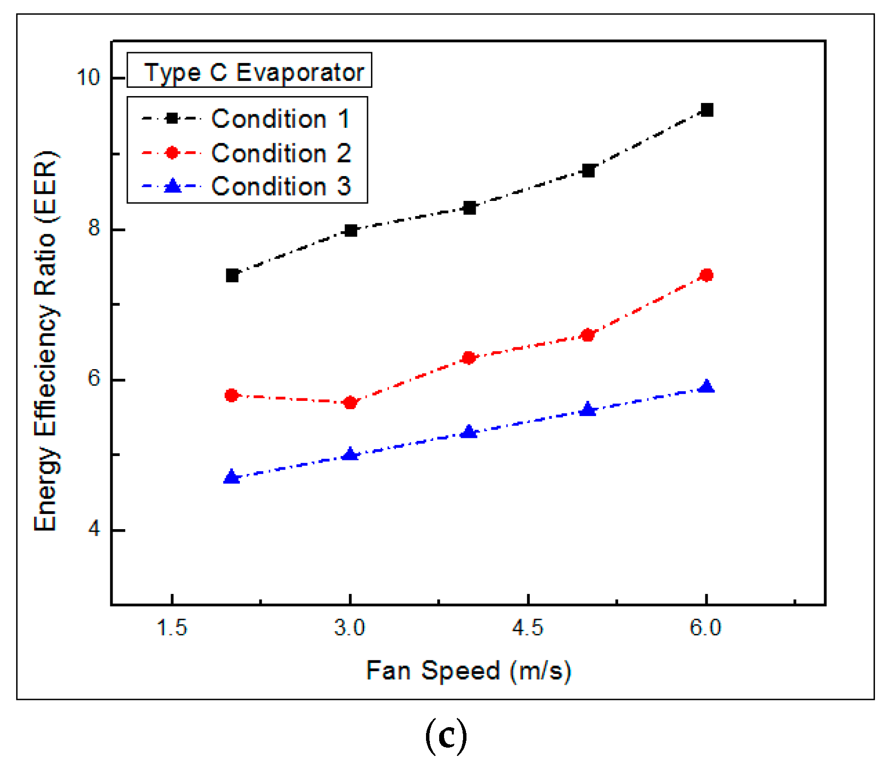
4. Results and Discussion

The EER was plotted against the fan speed for all the used evaporators at all prescribed conditions for types A, B, and C evaporators, respectively, as shown in Figure 2a–c. In all graphs, it can be observed that for a constant fan speed the increase in rate of mass flow of LPG through the evaporators and the EVP increased the EER. It can also be seen that with the escalate in the fan speed and the fixed mass rate of flow of LPG and EVP for the evaporators, the EER increased.
For condition 1, the highest EER was recorded for type A evaporator, i.e., approximately 11 at a very low fan velocity of 3.5 m/s. The minimum EER for type A evaporator was approximately 8.5 at a fan velocity of 1.5 m/s, which was approximately the maximum EER of condition 1 for the other two evaporators at high speeds of the fan, i.e., 14 m/s for type B evaporator and 6 m/s for type C evaporator. Under same conditions, it can be observed that the EER of type A evaporator was higher than those of the other two evaporators at low speeds of 1.5 to 3.5 m/s.

5. Conclusions

It was observed that the EER was a function of the mass flow rate and the EVP of the refrigerant flowing in the evaporators and the velocity of air flowing over the evaporators’ coils. It was also concluded that type A evaporator gave the maximum EER even at low speeds of interacting air and finned tube evaporators with high thermal conductivity and the same fin and tube material gave a high EER at low speeds compared with the finned tube evaporators having less thermally conductive fins and tube materials.

Conflicts of Interest

The corresponding author declares that this submission has no conflicts of interest of any type, on behalf of all authors.

References

  1. Setiyo, M.; Soeparman, S.; Hamidi, N.; Wahyudi, S. Cooling effect characteristics of a ½ cycle refrigeration system on an LPG fuel system. Int. J. Refrig. 2017, 82, 227–237. [Google Scholar] [CrossRef]
  2. Werpy, M.R.; Burnham, A.; Bertram, K. Propane Vehicles: Status, Challenges, and Opportunities; Center for Transportation Research, Energy Systems Division, Argonne National Laboratory: Lemont, IL, USA, 2010. [Google Scholar]
  3. Razus, D.; Brinzea, V.; Mitu, M.; Oancea, D. Burning Velocity of Liquified Petroleum Gas (LPG)−Air Mixtures in the Presence of Exhaust Gas. Energy Fuels 2010, 24, 1487–1494. [Google Scholar] [CrossRef]
  4. Setiyo, M.; Soeparman, S.; Wahyudi, S.; Hamidi, N. A simulation for predicting potential cooling effect on LPG-fuelled vehicles. AIP Conf. Proceedingsvol. 2016, 1717, 30002. [Google Scholar]
  5. Muzaffar, A.; Cheema, T.A.; Abbas, A.; Tayyab, M.; Ilyas, M.; Park, C.W. Performance analysis of liquified petroleum gas (LPG) driven half-cycle air conditioning system. Heat Mass Transf. 2020, 56, 3177–3197. [Google Scholar] [CrossRef]
  6. El-Morsi, M. Energy and exergy analysis of LPG (Liquified petroleum gas) as a drop in replacement for R134a in domestic refrigerators. Energy 2015, 86, 344–353. [Google Scholar] [CrossRef]
Figure 1. Schematic of the half-cycle air-conditioning system (HCACS) experimental test rig.
Engproc 12 00005 g001
Figure 2. Variations of the energy efficiency ratio (EER) with changing the fan speed for type A (a), type B (b), and type C (c) evaporators used in the study.
Engproc 12 00005 g002aEngproc 12 00005 g002b
Table 1. Evaporators’ summary used for experiments.
Type of EvaporatorType AType BType C
Tubes positioningIn-lineStaggeredIn-line
Tube/fin materials Cu/CuCu/mild steelCu/G. iron
Tube (Outer diameter, Inner diameter and length; unit: mm) 8, 6, and 1208, 6, and 12027, 24, and 220
Fin   ( t h i c k n e s s × w i d t h × l e n g t h ; unit: mm) 0.3 × 48 × 96 0.3 × 48 × 96 1 × 100 × 150
No and space between fins 122, 0.7 mm122, 0.7 mm23, 9 mm
Longitudinal–Transverse pitch ratio 111
Diagonal pitch-26.83 mm-
Numbers of rows and tubes/rows 2 and 42 and 42 and 3
Publisher’s Note: MDPI stays neutral with regard to jurisdictional claims in published maps and institutional affiliations.

