Proceeding Paper

Sliding Mode Control Based on Backstepping Approach for Microsatellite Attitude Pointing †

by
Halima Boussadia
1,*,
Arezki Mohamed Si Mohammed
2,
Nabil Boughanmi
1 and
Abdelkrim Meche
3
1
Department of Electronic, LARESI Laboratory, USTO-MB University, Oran 31000, Algeria
2
Department of Space Mechanic Research, Centre of Satellite Development, Oran 31000, Algeria
3
Department of Electronic, LSI Laboratory, USTO-MB University, Oran 31000, Algeria
*
Author to whom correspondence should be addressed.
Presented at the 1st International Conference on Computational Engineering and Intelligent Systems, Online, 10–12 December 2021.
Eng. Proc. 2022, 14(1), 24; https://doi.org/10.3390/engproc2022014024
Published: 15 March 2022

Abstract

:
The primary goal of this work is to present the design of sliding mode control, based on the backstepping approach, for the attitude tracking control of a micro-satellite, using reaction wheels. The presented technique is developed by combining sliding mode control with the backstepping technique, to achieve a fast and accurate tracking response. Firstly, backstepping and sliding mode controllers are developed. Then, the hybrid controller is designed. The selected controllers are applied to a Low Earth Orbit (LEO) micro-satellite, and they are compared in terms of accuracy, convergence time, power consumption, and maximum reaction wheel velocity. The simulation results clearly demonstrate the effectiveness of the presented technique.

1. Introduction

In recent years, satellites have become an important application area of new technological developments.
They are used in many fields, such as telecommunications, satellite surveillance, earth observation, and defense technologies. For the success of these missions, the satellite must be stabilized at a desired attitude.
The attitude is the orientation of the satellite in the space. In the absence of control, it evolves naturally under the effect of external disturbances [1]. Therefore, the attitude control problem is an interesting part of the research into new space technologies. It has attracted much attention in recent years because of the many types of space missions now being undertaken.
In satellite systems, the Attitude Determination and Control System (ADCS) is one of the most important systems, as it ensures the pointing of all satellite subsystems in the right direction during satellite missions (it ensures the pointing of the antenna into Earth’s direction, solar array into sun direction, sensors into target direction, and thrusters into thrust direction).
In practical situations, satellites are subject to different external disturbances, which are characterized by coupled and nonlinear dynamics. Their tasks have become more complex and diverse, which put forward higher requirements for the accuracy and stability of the satellite attitude system [2]. Thus, the design of the attitude controllers is usually difficult.
Due to the above-mentioned problem, a large variety of nonlinear controllers have been proposed. These controllers include sliding mode control [3,4], fuzzy control [5], backstepping control and feedback control [6,7]. Among these control techniques, the backstepping and sliding mode are the most robust controls. The advantage of these two controls is that they are based on the Lyapunov theory, and particularly on the second method of Lyapunov (direct method), which ensures stability.
The backstepping control has been very useful in the space field over the past few years. In [8], this technique was used with the inverse optimal control to stabilize spacecraft attitude. In [9], backstepping was based on a similar skew-symmetric structure. In [1], it was developed based on the adaptive design of Lyapunov. Also, in [10], it was used based on adaptive design, to develop an attitude controller in the presence of the uncertainties of inertia parameters. In [11], the authors presented control by integrator backstepping with internal stabilization.
The sliding mode control is based on a sliding surface and the state trajectory is brought to this surface. This technique has been used in many studies for spacecraft attitude control. It was designed for spacecraft attitude tracking in [12], and for flexible spacecraft in [13]. In [14], the sliding mode control was developed based on the artificial neural network, adjusted by a genetic algorithm, to control the attitude of Alsat-1 (the first Algerian satellite). In [15], the authors presented control by sliding mode under body angular velocity constraints.
The main advantages of the sliding mode technique are its fast state convergence and its simplicity of implementation, in comparison with the backstepping technique, but the latter is more accurate than the sliding mode control. Therefore, the combination of these two techniques provides good performance.
In this work, we combine the two presented techniques (sliding mode and backstepping) to obtain a fast and accurate tracking response, with the presented controller developed using the technique presented in [16]. To demonstrate its effectiveness, we give a comparison between backstepping, sliding mode, and hybrid controller, in terms of accuracy, convergence time, power consumption, and maximum reaction wheel velocity.
The paper is organized as follows: Section 2 presents the dynamic and kinematic models used for the satellite; Section 3, Section 4 and Section 5 describe the design of the control laws that are presented in this work; in the next section, we present the simulation results, andfinally, the conclusion of this paper is presented in Section 6.

2. Spacecraft Attitude Model

The dynamics of the spacecraft in inertial space, governed by Euler’s equations of motion, can be expressed as follows, in vector form as [16,17]:
I ω ˙ s I = C e x t + I ω s I × ( I ω s I + h ) h ˙
where, I = [ I x I y I z ] moment of inertia of spacecraft, ω s I = [ ω x ω y ω z ] T angular velocity vector in the inertial frame, h = [ h x h y h z ] T angular moment vector and C e x t = [ C x C y C z ] T external disturbance torque vector.
The kinematic equation, as follows, is expressed as:
q ˙ = 1 2 Ω q = 1 2 Λ ( q )
where, q = [ q 1 q 2 q 3 q 4 ] quaternion.
Ω = [ 0 ω oz ω oy ω ox ω oz 0 ω ox ω oy ω oy ω ox 0 ω oz ω ox ω oy ω oz 0 ]
Equation (4) is as follows:
Λ ( q ) = [ q 4 q 3 q 2 q 1 q 3 q 4 q 1 q 2 q 2 q 1 q 4 q 3 ]
The angular body rates referenced to the orbit coordinates can be obtained from the inertial referenced body rates by using the transformation matrix A, in the following, as [18]:
ω s o = ω s I A ω 0
where, ω s o = [ ω ox ω oy ω oz ] T is the angular velocity vector in the orbital reference frame.
The attitude matrix to transform any vector from the reference orbital to body coordinates in terms of quaternion is expressed in the following way, as:
A = [ q 1 2 q 2 2 q 3 2 + q 4 2 2 ( q 1 q 2 + q 3 q 4 ) 2 ( q 1 q 3 q 2 q 4 ) 2 ( q 1 q 2 q 3 q 4 ) q 1 2 + q 2 2 q 3 2 + q 4 2 2 ( q 2 q 3 + q 1 q 4 ) 2 ( q 1 q 3 + q 2 q 4 ) 2 ( q 2 q 3 q 1 q 4 ) q 1 2 q 2 2 + q 3 2 + q 4 2 ]
From Equations (1) and (2), the satellite mathematical model can be written in the following way, as:
x ˙ = f ( x ) + B u
y = H x
where,
  • x = [ q 1 , q 2 , q 3 , q 4 , ω x , ω y , ω z ] T is the state vector;
  • B = [ 0 4 × 3 I 3 × 3 ] T is the control matrix;
  • H = [ I 4 × 4 0 4 × 3 ] is the observation matrix;
  • U = h ˙ is the control input torque.
f ( x ) = [ 0.5 ( ω oz q 2 ω oy q 3 + ω ox q 4 ) 0.5 ( ω oz q 1 + ω ox q 3 + ω oy q 4 ) 0.5 ( ω oy q 1 ω ox q 2 + ω oz q 4 ) 0.5 ( ω ox q 1 ω oy q 2 ω oz q 3 ) I x 1 ( C x ( I z I y ) ω y ω z ω y h z + ω z h y ) I y 1 ( C y ( I x I z ) ω x ω z + ω x h z ω z h x ) I z 1 ( C z ( I y I x ) ω x ω y ω x h y + ω y h x ) ]

3. Backstepping Control Design

This section presents the design of the backstepping control technique, which is inspired by [19].
The presented algorithm is described in two steps, as follows:

3.1. Step 1

Firstly, we define the first and the second variable of backstepping, below:
z 1 = x 1 = q e = q c q
z 2 = x 2 α 1
where, α 1 is a virtual control law.
The time derivative of z 1 is expressed, below, as:
z ˙ 1 = x ˙ 1 = q ˙ e = q c ( 1 2 Λ ( q ) ω s o )
The first Lyapunov function is defined, below, as:
V 1 ( z 1 ) = z 1 T z 1
Its time derivative is expressed, below, as:
V ˙ 1 = 2 z 1 T z ˙ 1 = z 1 T G ( q ) z 2 + z 1 T G ( q ) α 1
where,
G ( q ) = q c Λ ( q )
To make V ˙ 1 negative, α 1 is chosen as the following:
α 1 = k 1 G ( q ) T z 1
where, k 1 is a positive gain matrix.
The time derivative of V 1 becomes the following:
V ˙ 1 = z 1 T G ( q ) k 1 G ( q ) T z 1 + z 1 T G ( q ) z 2
The term z 1 T G ( q ) z 2 will be eliminated in the next step.

3.2. Step 2

The time derivative of z 2 is expressed in the following way, as:
z ˙ 2 = ω ˙ s o α ˙ 1
where,
ω s o = ω s I A ω 0
We replace Equation (18) in (17), obtaining the following:
z ˙ 2 = ω ˙ s I A ˙ ω 0 α ˙ 1
I z ˙ 2 = I ω ˙ s I I A ˙ ω 0 I α ˙ 1
The second Lyapunov function is defined, below, as:
V 2 ( z 1 , z 2 ) = V 1 ( z 1 ) + 1 2 z 2 T I z 2
Its time derivative is expressed, below, as:
V ˙ 2 = V ˙ 1 + z 2 T I z ˙ 2
V ˙ 2 = z 1 T G ( q ) k 1 G ( q ) T z 1 + z 1 T G ( q ) z 2 + z 2 T [ ( C e x t ω s I × ( I ω s I + h ) h ˙ ) ] I A ˙ ω 0 I α ˙ 1
To makes V ˙ 2 negative, the control law h ˙ is chosen, seen below, as:
h ˙ = k 2 z 2 + G ( q ) T z 1 + ( C e x t ω s I × ( I ω s I + h ) ) I A ˙ ω 0 I α ˙ 1

4. Sliding Mode Control Design

In this section, sliding mode control law is developed. The sliding mode control SMC (also called variable structure control) design can be divided into three steps, explained below.

4.1. Choice of Sliding Surface

The sliding surface has a linear form, defined below, as:
S = q ˙ e + W q e
where, q e = q c q is quaternion error, q c is quaternion command and W is diagonal gain matrix.

4.2. Convergence and Existence Conditions

The convergence and existence conditions force the dynamic of the system to converge to the sliding surface, which is presented in the first step. This condition can be characterized by the following:
S S ˙ < 0

4.3. Establishment of the Control Law

The sliding mode control law is divided into two main parts, seen in the following [18]:
U = U e q + U d
The first component of the proposed controlleris U e q , which will make sliding surface S invariant, is calculated by setting the derivate of the sliding surface to zero [20], shown below:
S ˙ = 0
The second component is an extra control effort, which forces the quaternion and angular velocity component to reach the sliding surface in a finite time, in spite of disturbances, and it is computed according to constant reaching law, seen below, as [20]:
U d = k s i g n ( S )
where, k is a positive gain.
To eliminate the chattering phenomenon caused by the sign function, we can replace this function by a saturation function.
Finally, we obtain the command in the following way, as:
U = k s i g n ( S ) + 1 2 q c I 1 [ W q c q ˙ + q c ( 1 2 Λ ˙ ω s o 1 2 Λ A ˙ ω 0 + 1 2 Λ I 1 ( C e x t ω s I × ( I ω s I + h ) ) ) ]
where ω 0 is the mean orbital angular velocity.
Λ ( q ) = [ q 4 q 3 q 2 q 3 q 4 q 1 q 2 q 1 q 4 q 1 q 2 q 3 ]

5. Backstepping–Sliding Mode Control Design

In this section, we develop a sliding mode controller based on the backstepping approach, using the technique presented in [16]. The presented technique is designed from the fusion of the backstepping control presented in Section 3, and the sliding mode control presented in Section 4.
Firstly, we define the first variable of backstepping and the sliding surface as follows:
z 1 = x 1 = q e = q c q
S = q ˙ e + W q e
The Lyapunov functions are defined in the following way, as:
V 1 ( z 1 ) = z 1 T z 1
V 2 ( z 1 , S ) = V 1 ( z 1 ) + 1 2 S T S
The time derivative of V 2 is expressed, below, as:
V ˙ 2 = 2 z 1 T z ˙ 1 + S T S ˙
We chose the time derivative of the sliding surface, satisfying the condition S T S ˙ 0 [1], shown below:
S ˙ = a 1 s a t ( S ) β 1 S
S ˙ = q c q ¨ + W q c q ˙
S ˙ = q c [ W q c q ˙ + q c ( 1 2 Λ ˙ ω s o 1 2 Λ A ˙ ω 0 + 1 2 Λ I 1 ( C e x t ω s I × ( I ω s I + h ) ) 1 2 Λ I 1 h ˙ ) ] + W q c q ˙
Finally, the control law is given as follows:
U = ( 1 2 q c Λ I 1 ) 1 [ 1 2 q c Λ ˙ ω s o 1 2 q c Λ A ˙ ω 0 + 1 2 q c Λ I 1 ( C e x t ω s I × ( I ω s I + h ) ) ] + a 1 s a t ( S ) + β 1 S

6. Simulation Results

The simulation results are obtained using the following parameters, in Table 1.
The desired attitude for the Euler angles is [ 10 30 20 ] . And the Control parameters are presented in Table 2.
For a more detailed analysis, the RMS errors, the convergence time, the power consumption, and the maximum reaction wheel velocity were calculated, presented in Table 3.
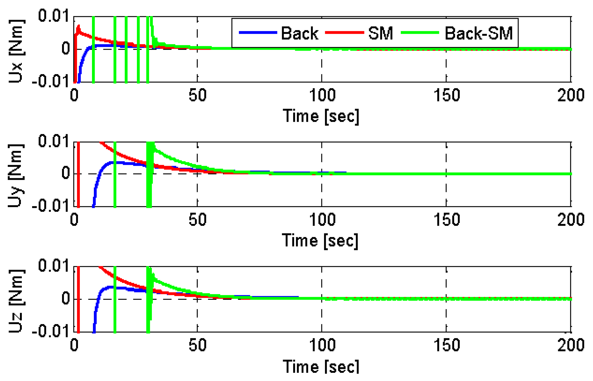
Figure 1, Figure 2 and Figure 3 show the simulation results of the backstepping, sliding mode and hybrid control. We clearly observed that the three controllers ensure the attitude tracking, but the Euler angles, calculated by the sliding mode and hybrid controllers, are converged after a short period, in comparison with Euler angles calculated by the backstepping controller. The analysis of Table 3 shows that the backstepping controller was characterized by a low convergence time (127.30 s), and the sliding mode controller was characterized by a good accuracy (0.00068). We conclude that the backstepping controller is better than the sliding mode, in terms of accuracy. But in terms of convergence time, the sliding mode controller is better than the backstepping. On the other hand, the backstepping–sliding controller was characterized by high performance, in terms of convergence time and accuracy (109 s and 0.0007 degrees respectively) because it combined the advantages of the two controllers (backstepping and sliding mode).Wealso observed that the two first controllers were characterized by the same energy consumption (2.45 × 10⁻⁵ W), but the maximum reaction wheel velocity of the sliding mode controller was higher than that of the backstepping controller. On the other hand, the hybrid controller was characterized by high power consumption and a high maximum reaction wheel velocity (0.065 W and 729.85 rpm respectively). This is due to the hybridization of the two techniques (backstepping and sliding mode).

7. Conclusions

In this work, we presented the design of sliding mode control, based on the backstepping approach, for Low Earth Orbit (LEO) micro-satellite attitude stabilization, using three axis controls by reaction wheels. The presented technique is developed by combining sliding mode control with the backstepping technique. Firstly, a nominal backstepping controller and nominal sliding mode controller were developed. Then, a combination of these two methods was designed to achieve fast and accurate tracking responses. The simulation results demonstrate the effectiveness of the presented technique. We found that the presented controller gives good performances because of the hybridization of the two techniques (backstepping and sliding mode).

Author Contributions

Writing—review and editing, H.B.; supervision, A.M.S.M. and N.B.; methodology, A.M. All authors have read and agreed to the published version of the manuscript.

Funding

This research received no external funding.

Institutional Review Board Statement

Not applicable.

Informed Consent Statement

Informed consent was obtained from all subjects involved in the study.

Data Availability Statement

The authors confirm that the data supporting the findings of this study are available within the article.

Conflicts of Interest

The authors declare that they have no conflict of interest.

References

  1. Mohammed, M.A.S.; Boussadia, H.; Bellar, A.; Adnane, A. Adaptive backstepping control for three axis microsatellite attitude pointing under actuator faults. In Proceedings of the 13th European Workshop on Advanced Control and Diagnosis (ACD 2016), Lille, France, 17–18 November 2016. [Google Scholar]
  2. Boskovic, J.D.; Li, S.M.; Mehra, M.K. Robust adaptive variable structure control of spacecraft under input saturation. J. Guid. Control Dyn. 2001, 24, 14–22. [Google Scholar] [CrossRef]
  3. Lu, K.; Xia, Y.; Zhu, Z.; Basin, M.V. Sliding mode attitude tracking of rigid spacecraft with disturbance. J. Frankl. Inst. 2012, 349, 413–440. [Google Scholar] [CrossRef]
  4. Zou, A.; Kumar, K.D. Adaptive fuzzy fault-tolerant attitude control of spacecraft. Control Eng. Pract. 2011, 19, 10–21. [Google Scholar] [CrossRef]
  5. Costic, B.T.; Dawson, D.M.; Queiroz, M.S.; Kapila, V. Quaternion based attitude tracking control without velocity measurements. In Proceedings of the 39th IEEE Conference on Decision and Control, Sydney, Australia, 12–15 December 2000. [Google Scholar]
  6. Wong, H.; de Queiroz, M.S.; Kapila, V. Adaptive tracking control using synthesized velocity from attitude measurements. Automatica 2001, 37, 947–953. [Google Scholar] [CrossRef]
  7. Boussadia, H.; Mohammed, A.S.; Boughanmi, N.; Bellar, A. Adaptive Backstepping control for Microsatellite under Inertia Uncertainties. In Proceedings of the 39th IEEE Conference on Recent Advances in Space Technologies, Istanbul, Turkey, 19–22 June 2017. [Google Scholar]
  8. Krstié, M.; Tsiotras, P. Inverse optimale stabilization of a rigid spacecraft. IEEE Trans. Autom. Control 1999, 44, 1014–1027. [Google Scholar]
  9. Liu, Y.C.; Zhang, T.; Song, J.Y. Attitude controller design for larger angle maneuver based on similar skew-symmetric structure. J. Astronaut. 2009, 30, 1017–1023. [Google Scholar]
  10. Doruk, R.Ö.; Kocaoğlan, E. Satellite attitude control by integrator backstepping with internal stabilization. Aircr. Eng. Aerosp. Technol. 2008, 80, 3–10. [Google Scholar] [CrossRef]
  11. Crassidis, J.L.; Vadali, S.R.; Markley, F.L. Optimal Tracking of Spacecraft Using Variable-Structure Control. In Proceedings of the Flight Mechanics/Estimation Theory Symposium, NASA-Goddard Space Flight Center, NASA/CP-1999-209235, Greenbelt, MD, USA, 18–20 May 1999; pp. 201–214. [Google Scholar]
  12. Hu, Q.; Xie, L.; Wang, Y. Sliding Mode Attitude and Vibration Control of Flexible Spacecraft with Actuator Dynamics. In Proceedings of the IEEE International Conference on Control and Automation, Guangzhou, China, 30 May–1 June 2007. [Google Scholar]
  13. Mohammed, A.M.S. Three Axis Attitude Control Using Sliding Mode Based on the Artificial Neural Network for Low Earth Orbit Microsatellite. Int. J. Syst. Appl. Eng. Dev. 2012, 6, 223–233. [Google Scholar]
  14. Azza El-S, I.; Tobal, A.M.; Sultan, M.A. Satellite Attitude Maneuver using Sliding Mode Control under Body Angular Velocity Constraints. Int. J. Comput. Appl. 2012, 975, 8887. [Google Scholar]
  15. Bouadi, H.; Bouchoucha, M.; Tadjine, M. Sliding Mode Control based on Backstepping Approch for an UAV Type-Quadrotor. World Acad. Sci. Eng. Technol. 2007, 26, 22–27. [Google Scholar]
  16. Wertz, J.R. Spacecraft Attitude Determination and Control; D. Reidel Publishing Company: Boston, MA, USA, 1986. [Google Scholar]
  17. Sidi, M. Spacecraft Dynamics and Control; Cambridge University Press: Cambridge, UK, 1997. [Google Scholar]
  18. Kanellakopoulos, I.; Kokotovic, P.V.; Morse, A.S. Systematic Design of Adaptive Controllers for Feedback Linearizable Systems. IEEE Trans. Autom. Control 1991, 36, 1241–1253. [Google Scholar] [CrossRef] [Green Version]
  19. Young, K.; Utkin, V.; Özgüner, Ü. A control engineer’s guide to sliding mode control. IEEE Trans. Autom. Control 1999, 7, 328–342. [Google Scholar] [CrossRef] [Green Version]
  20. Slotine, J.J.E.; Li, W. Applied Nonlinear Control; Prentice-Hall Inc.: Hoboken, NJ, USA, 1991. [Google Scholar]
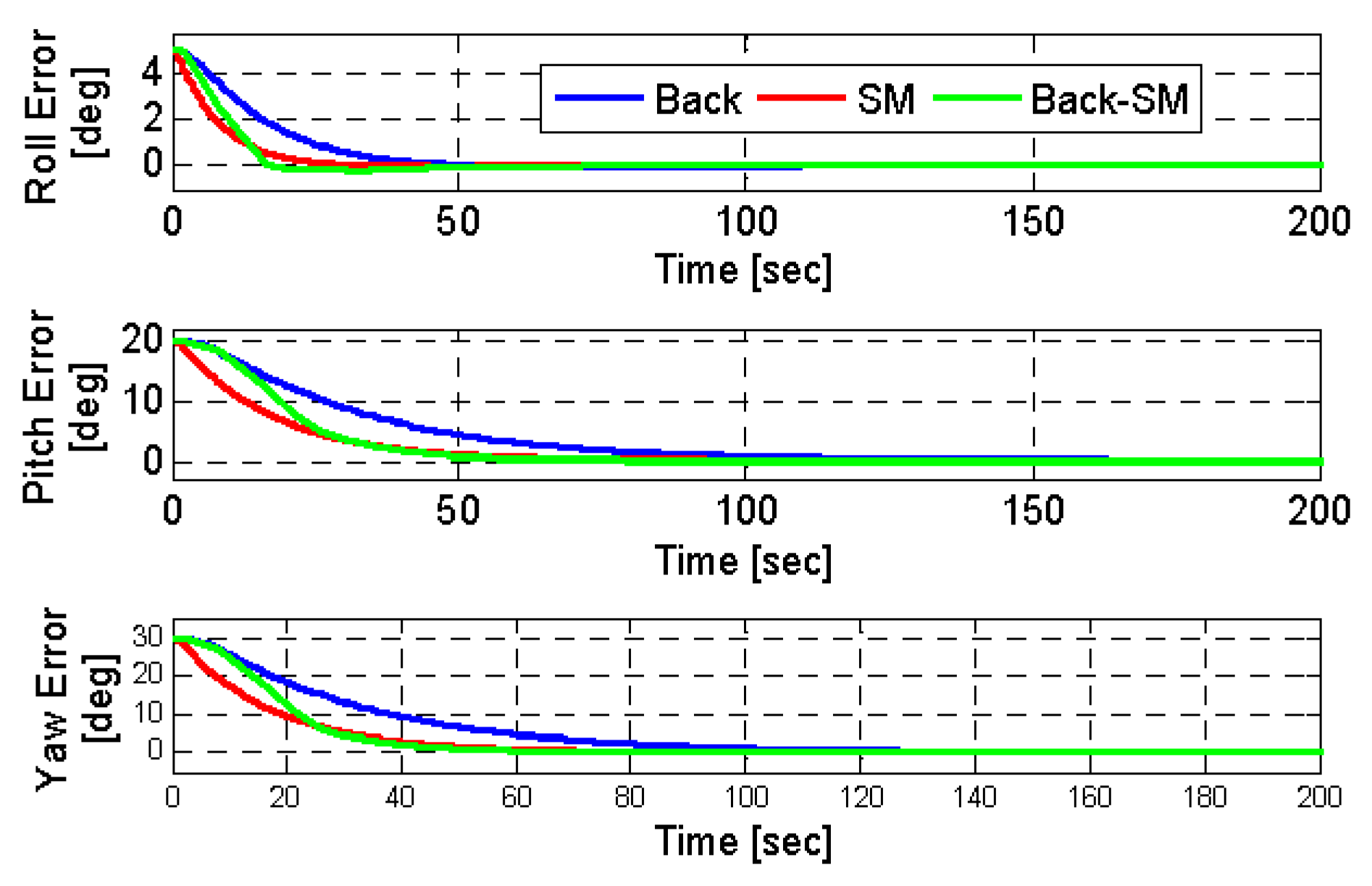
Figure 1. Euler angles errors.
Engproc 14 00024 g001
Figure 2. Attitude tracking control of Euler angles.
Engproc 14 00024 g002
Figure 3. Control Torques.
Engproc 14 00024 g003
Table 1. Satellite Parameters.
ParameterValue
Inertia [kgm2] diag ( [ 12 14 10 ] )
Orbit [km]686
Inclination [deg]98
Initial attitude [deg] [ 5 10 10 ]
Initial angular rate [deg/sec] [ 0 0.06 0 ]
External Torques [N.m] [ 10 7 ( 5   cos ( ω 0 t ) + 1 ) 10 7 ( 5   cos ( ω 0 t ) + 2   sin ( ω 0 t ) ) 10 7 ( 5   cos ( ω 0 t ) + 1 ) ]
Table 2. Control Parameters.
Sliding Mode PrametersBackstepping PrametersSliding Mode-Backstepping Prameters
W k k 1 k 2 W a 1 β 1
0.06eye(3)200eye(3)0.01eye(3)8eye(3)0.08eye(3)110eye(3)3eye(3)
Table 3. Performance evaluation of the different controllers.
Sliding ModeBacksteppingHybrid
RMS errors [deg]0.00130.000680.0007
Convergence time [sec] Roll Pitch Yaw [ 50 . 85 126 . 30 127 . 30 ] Roll Pitch Yaw [ 95 . 75 178 . 43 178 . 06 ] Roll Pitch Yaw [ 66 . 47 112 . 55 108 . 89 ]
Power consumption2.45 × 10−52.46 × 10−50.065
Maximum reaction wheel velocity233.29526.64729.85
Publisher’s Note: MDPI stays neutral with regard to jurisdictional claims in published maps and institutional affiliations.