Proceeding Paper

Thermal Stability Analysis of a PCM-Based Energy Storage System †

Department of Mechanical Engineering, Faculty of Mechanical & Aeronautical Engineering, University of Engineering and Technology Taxila, Taxila 47050, Punjab, Pakistan
*
Author to whom correspondence should be addressed.
Presented at the 2nd International Conference on Advances in Mechanical Engineering (ICAME-22), Islamabad, Pakistan, 25 August 2022.
Eng. Proc. 2022, 23(1), 20; https://doi.org/10.3390/engproc2022023020
Published: 21 September 2022
(This article belongs to the Proceedings of The 2nd International Conference on Advances in Mechanical Engineering)

Abstract

:
A key factor for increasing the life of electronic devices and preventing early failure is the implementation of thermal management techniques. In thermal management, phase change materials (PCMs) are generally used. There have been a few studies conducted on PCM stability. Using thermal cycle tests, PCM (RT 42)-based energy storage systems with and without pin fins were evaluated for thermal stability. The material used for the pin fins and the heat sink was Aluminum 2024-T851. During the thermal cycle tests, the PCM-based heat sinks at 10 W had a maximum temperature difference of 1.088 °C. This leads to the PCM-based heat sink being stable during charging and discharging. According to the results of the thermal cycle tests conducted on the PCM and triangular pin-fin-based heat sink, the maximum temperature difference between the tests was 0.58 °C at 10 W. Based on the results, the PCM triangular pin-fin heat sink is stable during charging and discharging.

1. Introduction

Sharma et al. [1] evaluated whether urea was conducted, and the thermal cycle tests showed a change in the latent heat of the fusion and melting point of −21% and −23.6 °C, respectively. It was observed that the urea did not melt after 50 cycles and −21%. Tauseef-ur-Rehman et al. [2] investigated the operating time behavior of an unfinned heat sink cavity with PCM. Sodhi et al. [3], depending on the criteria, described that the system might have advantages over mono PCM systems. Compared to multi-PCMs, a single PCM system can charge and discharge more efficiently. Thermal optimization using phase change materials-based systems has been refined to prevent premature equipment malfunction and maintain equipment reliability by Atouei et al. and Ali [4,5]. PCMs with high latent heat storage capability, excellent thermal stability, and adequate melting/freezing temperatures have sparked an interest in thermal control applications such as thermal management electronic devices, as evidenced by Motahar et al. [6].

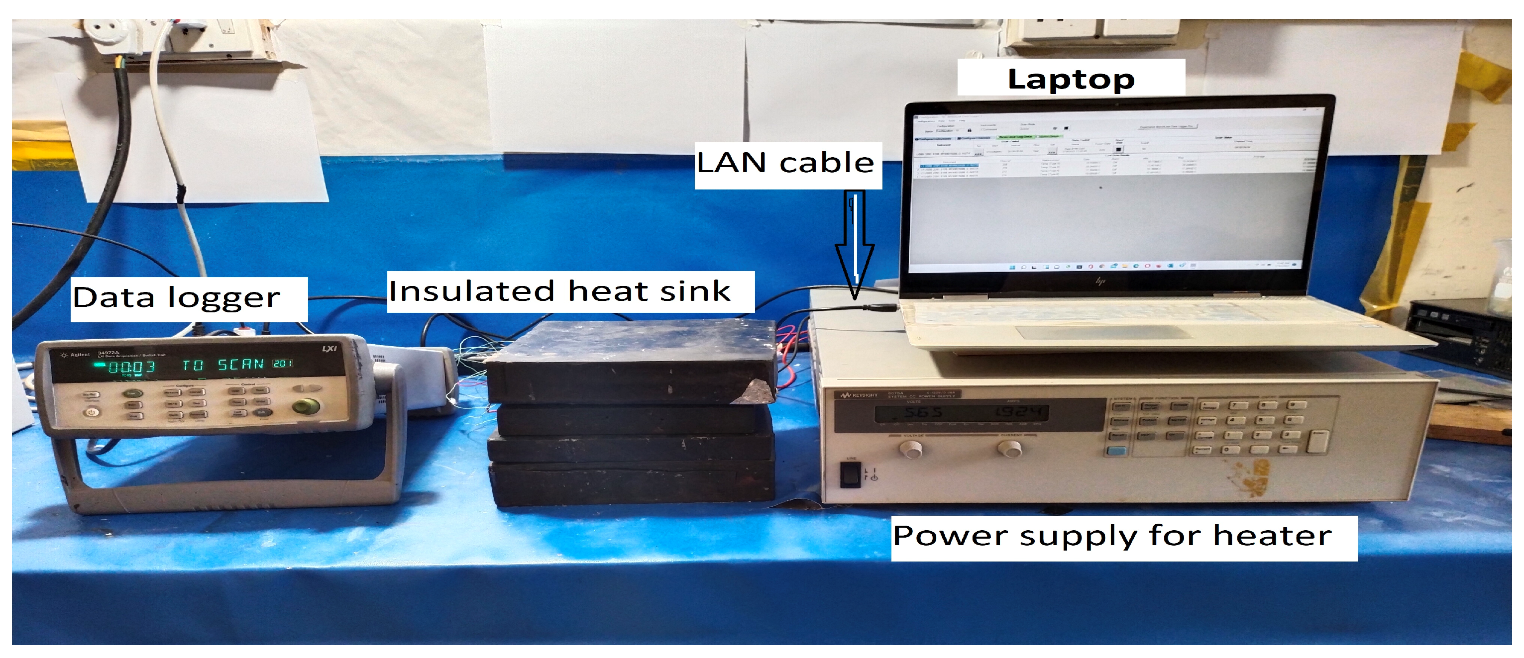
2. Experimental Setup

An experimental setup is illustrated in Figure 1, with labels for all of the components used in the experiment. A PCM (RT-42) was used for the experiment. In recent experimental research investigations, A. Arshad [7] reported that in the passive thermal management of portable electronic devices, a heat sink that occupies 9% of the volume fraction is the most efficient, given as:
ψ PCM = [ V PCM V s V f ]
In Equation (1), the PCM volume fraction is denoted by ψPCM, the heat-sink volume by Vs, and the fin volume by Vf. This experiment used 220 mL or 0.22 kg PCM (RT-42) with a power supply of 10 W.

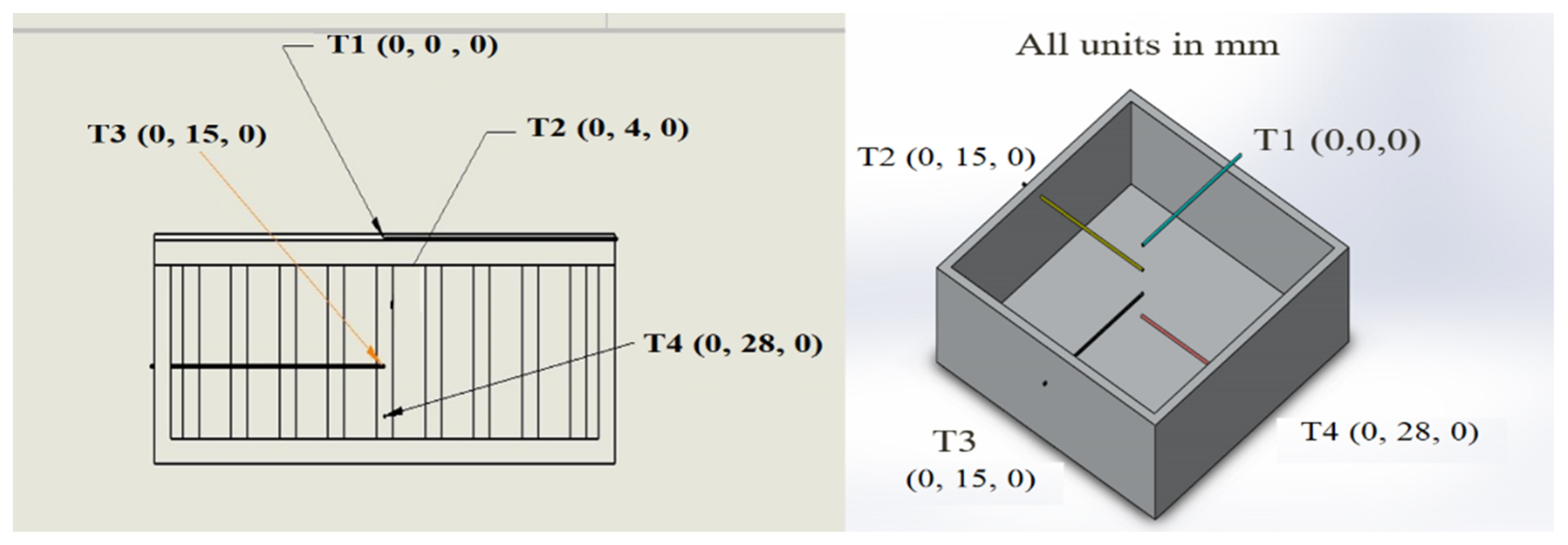
Thermocouples Position

In that experiment, a K-type thermocouple was used. Figure 2 shows that the four thermocouples (T1, T2, T3, and T4) were positioned at various heights throughout the cavity.

3. Results and Discussion

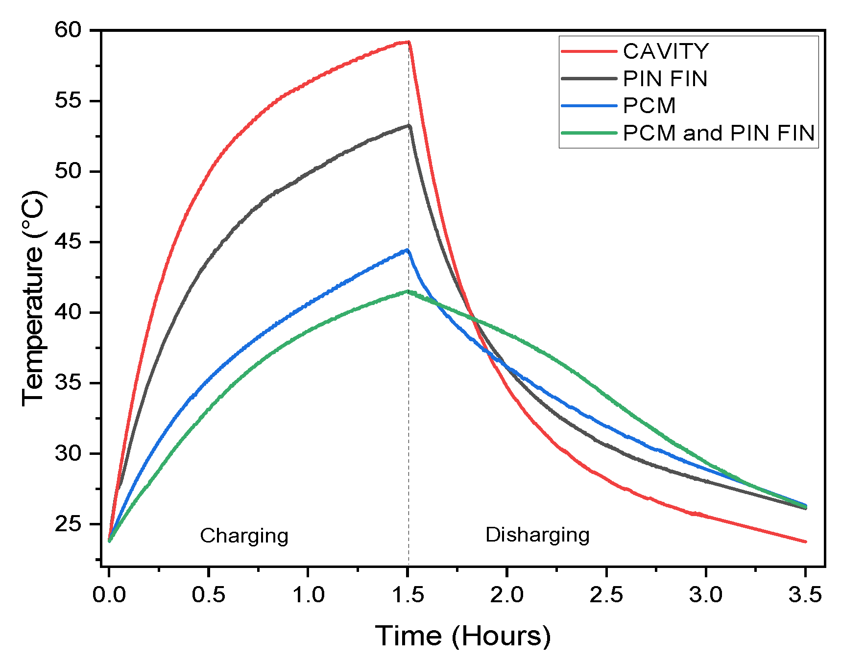
3.1. Experimentally Calibration of the Heat Sink

This experiment model is validated with a simple cavity. A comparison of the experimental results of the heat sink and experimental cases can be found in Figure 3. The experimental results supported the validity of the current experimental model, indicating that the current model could be used in future studies.

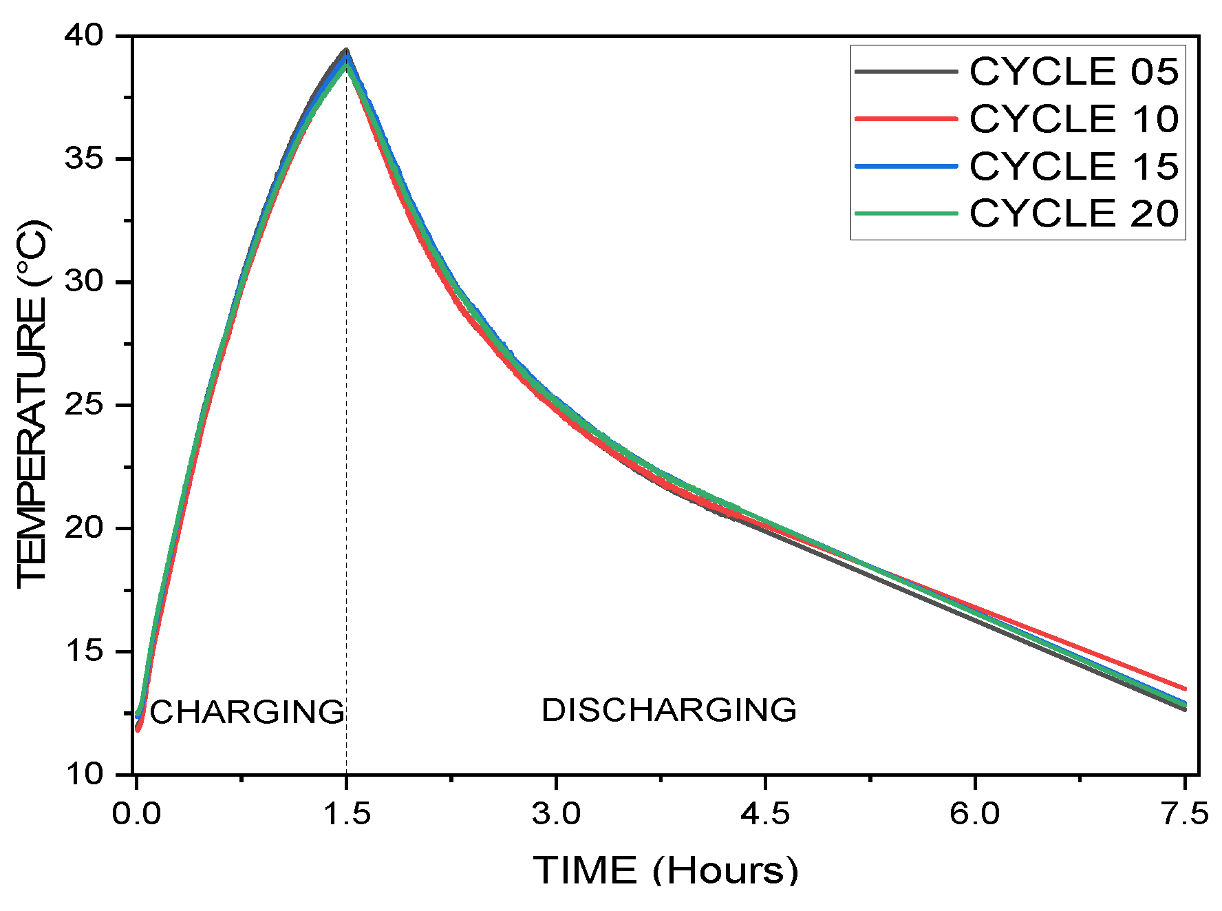
3.2. Analysis of Thermal Stability of PCM-Based Energy Storage System

A temperature versus time diagram is depicted in Figure 4, detailing the charging and discharging for different thermal cycle tests on PCM-based heat sinks. This experiment conducted twenty thermal cycling tests to determine the stability. The thermal cycle tests were stopped because the temperature rarely changed during charging and discharging. To calculate the results and compare the thermal cycles, 05, 10, 15, and 20 were selected. Figure 4 shows the comparison of the thermocouple 4 results. After charging for 1.5 h, the maximum temperature for thermal cycle 20 was 44.821 °C, and the minimum temperature for thermal cycle 05 was 43.733 °C; so, there was a maximum temperature difference of 1.088 °C, as shown in Table 1, and all of the thermal cycles reached room temperature after discharging for 3.25 h, as shown in Figure 5.

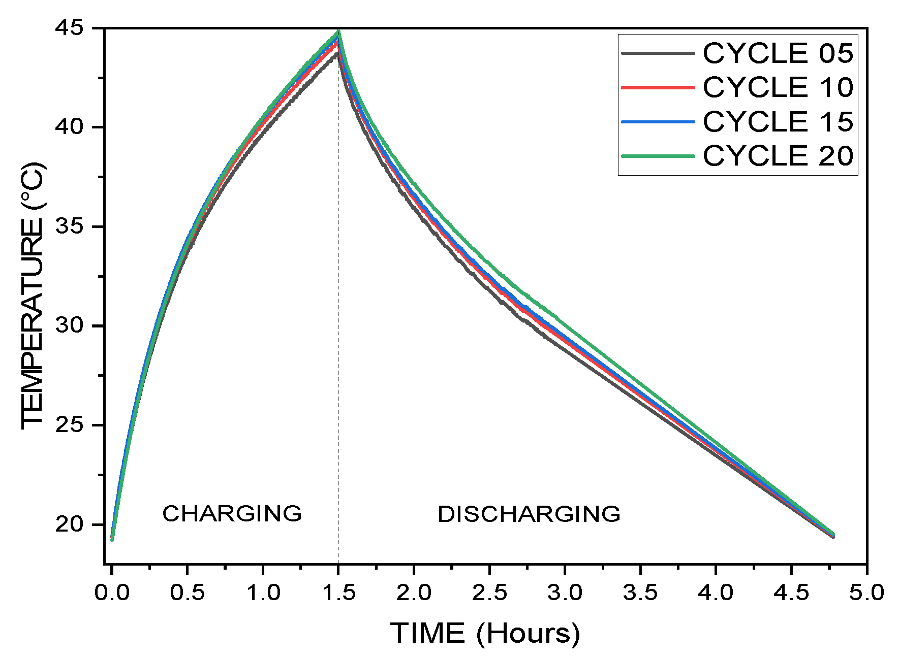
3.3. Analysis of Thermal Stability of PCM and Triangular Pin Fin-Based Energy Storage System

According to H. M. Ali et al. [8], pin-fins arranged in a triangular configuration are best suited for heat transfer, whether with or without PCM. This experiment conducted twenty thermal cycling tests to analyze the stability. The thermal cycle tests were stopped since the temperature rarely changed during charging and discharging. The thermal cycles, 05, 10, 15, and 20, were selected to calculate and compare the results. A comparison of the thermocouple 4 results can be seen in Figure 5. After charging for 1.5 h, thermal cycle 05 reached a maximum temperature of 39.429 °C, and thermal cycle 20 reached a minimum temperature of 38.849 °C; so, the maximum deviation was 0.58 °C, as shown in Table 1, and all of the thermal cycles reached room temperature after discharging for 6 h, as depicted in Figure 5.

4. Conclusions

Energy storage systems based on PCMs were stable under the thermal cycle tests, with a maximum temperature deviation of 1.088 °C. Moreover, the PCM and triangular pin-fin heat sink performed well in the thermal cycle tests, with maximum temperature deviations of 0.58 °C, indicating the stability of the energy storage systems. The experiment’s drawback was that the discharge took too long to reach room temperature.

Author Contributions

Conceptualization, M.U.M. and A.H.; methodology, M.U.M. and A.H.; software, M.U.M. and A.H.; validation, M.U.M. and A.H.; formal analysis, M.U.M. and A.H.; investigation, M.U.M. and A.H.; data curation, A.H.; writing—original draft preparation, M.U.M.; writing—review and editing, M.U.M. and A.H.; supervision, M.U.M.; project administration, M.U.M. All authors have read and agreed to the published version of the manuscript.

Funding

This research received no external funding.

Institutional Review Board Statement

Not applicable.

Informed Consent Statement

Not applicable.

Data Availability Statement

Not applicable.

Acknowledgments

The authors gratefully acknowledge the support from the University of Engineering and Technology, Taxila, Pakistan under its Advanced Studies Research and Technologies.

Conflicts of Interest

The authors declare no conflict of interest.

References

  1. Sharma, A.; Sharma, S.D.; Buddhi, D.; Sawhney, R.L. Thermal Cycle Test of Urea for Latent Heat Storage Applications. Int. J. Energy Res. 2001, 25, 465–468. [Google Scholar] [CrossRef]
  2. Rehman, T.U.; Ali, H.M.; Saieed, A.; Pao, W.; Ali, M. Copper Foam/PCMs Based Heat Sinks: An Experimental Study for Electronic Cooling Systems. Int. J. Heat Mass Transf. 2018, 127, 381–393. [Google Scholar] [CrossRef]
  3. Wang, T.; Almarashi, A.; Al-Turki, Y.A.; Abu-Hamdeh, N.H.; Hajizadeh, M.R.; Chu, Y.M.; Sodhi, G.S.; Muthukumar, P.; Arshad, A.; Jabbal, M.; et al. Compound Charging and Discharging Enhancement in Multi-PCM System Using Non-Uniform Fin Distribution. Therm. Sci. Eng. Prog. 2021, 18, 299–314. [Google Scholar] [CrossRef]
  4. Atouei, S.A.; Rezania, A.; Ranjbar, A.A.; Rosendahl, L.A. Protection and Thermal Management of Thermoelectric Generator System Using Phase Change Materials: An Experimental Investigation. Energy 2018, 156, 311–318. [Google Scholar] [CrossRef]
  5. Ali, H.M. Applications of Combined/Hybrid Use of Heat Pipe and Phase Change Materials in Energy Storage and Cooling Systems: A Recent Review. J. Energy Storage 2019, 26, 100986. [Google Scholar] [CrossRef]
  6. Motahar, S.; Jahangiri, M. Transient Heat Transfer Analysis of a Phase Change Material Heat Sink Using Experimental Data and Artificial Neural Network. Appl. Therm. Eng. 2020, 167, 114817. [Google Scholar] [CrossRef]
  7. Arshad, A.; Ali, H.M.; Ali, M.; Manzoor, S. Thermal Performance of Phase Change Material (PCM) Based Pin-Finned Heat Sinks for Electronics Devices: Effect of Pin Thickness and PCM Volume Fraction. Appl. Therm. Eng. 2017, 112, 143–155. [Google Scholar] [CrossRef]
  8. Ali, H.M.; Ashraf, M.J.; Giovannelli, A.; Irfan, M.; bin Irshad, T.; Hamid, H.M.; Hassan, F.; Arshad, A. Thermal Management of Electronics: An Experimental Analysis of Triangular, Rectangular and Circular Pin-Fin Heat Sinks for Various PCMs. Int. J. Heat Mass Transf. 2018, 123, 272–284. [Google Scholar] [CrossRef]
Figure 1. Actual view of the experimental setup.
Engproc 23 00020 g001
Figure 2. Schematic of thermocouple position. Left, 2D Front View of thermocouples position. Right, 3D Thermocouple Coordinate in Heat Sink.
Engproc 23 00020 g002
Figure 3. Experimental Validation for the heat sink.
Engproc 23 00020 g003
Figure 4. Thermal cycle tests analysis of PCM-based energy storage system.
Engproc 23 00020 g004
Figure 5. Thermal cycle tests analysis of PCM and triangular pin fin-based energy storage system.
Engproc 23 00020 g005
Table 1. After charging, the highest temperature, and the temperature differential for Thermal Cycle Tests (TCTs).
TCTs FOR PCM-BASED HEAT SINKTCTs FOR PCM & PIN FIN BASED HEAT SINK
MAXIMUM TEMPERATUREMAXIMUM TEMPERATURE
Cycle 5 (C5)Cycle 10 (C10)Cycle 15 (C15)Cycle 20 (C20)Cycle 5 (C5)Cycle 10 (C10)Cycle 15 (C15)Cycle 20 (C20)
43.733 °C44.286 °C44.582 °C44.821 °C39.429 °C38.884 °C39.139 °C38.849 °C
DIFFERENCE IN TEMPERATURE DURING TCTsDIFFERENCE IN TEMPERATURE DURING TCTs
C10–C50.553 °C C5–C100.545 °C
C15–C50.849 °C C5–C150.29 °C
C20–C51.088 °C C5–C200.58 °C
C15–C100.296 °C C15–C100.255 °C
C20–C100.535 °C C10–C200.035 °C
C20–C150.239 °C C15–C200.29 °C
Publisher’s Note: MDPI stays neutral with regard to jurisdictional claims in published maps and institutional affiliations.

