Proceeding Paper

Deep Rolling of Bores Using Centrifugal Force †

1
Laboratory for Machine Tools and Production Engineering (WZL), RWTH Aachen University, 52074 Aachen, Germany
2
Fraunhofer Institute for Production Technology, 52074 Aachen, Germany
*
Author to whom correspondence should be addressed.
Presented at the 28th Saxon Conference on Forming Technology SFU and the 7th International Conference on Accuracy in Forming Technology ICAFT, Chemnitz, Germany, 2–3 November 2022.
Eng. Proc. 2022, 26(1), 20; https://doi.org/10.3390/engproc2022026020
Published: 16 November 2022

Abstract

:
Deep rolling is a mechanical surface treatment for the specific modification of edge zone properties. In this process, the surface is plastically deformed by a rolling element. The roughness, residual stresses and hardness in particular can be positively influenced. An external pressure unit is usually used to generate the forces required for plastic deformation. The acquisition costs associated with the pressure unit and the space required reduce the attractiveness of deep rolling. In this work, the possibility of generating the required forces by exploiting the rotational speed of machining center spindles for processing bores is shown.

1. Introduction

Deep rolling is a manufacturing process used to specifically modify the surface area properties of specimens [1]. In particular, roughness [2], residual stresses [3] and hardness are influenced [4]. The manufacturing process is mostly used in machining centers or lathes [5]. During deep rolling, the surface area of specimens is incrementally plastically formed by a force-loaded rolling element that is guided over the surface. The force required for plastic forming is commonly generated by a hydraulic unit [5]. The hydraulic units for cooling lubricants installed in machining centers or lathes are usually unable to provide the process pressures required for deep rolling. Therefore, additional hydraulic units are required, which are associated with high acquisition costs and a certain space requirement. One possible approach to provide the necessary process forces when machining bores without an additional hydraulic unit is to utilize the rotational speed and thus the centrifugal force of the machining centers. Centrifugal force is already successfully used in machining for actuating tools [6]. For the utilization of centrifugal force in deep rolling, however, it is unclear whether the rotational speeds of conventional machining centers are sufficient to plastically form the surface area of specimens.
Therefore, this work investigated whether centrifugal force may be used as an alternative to hydraulic units for force generation during deep rolling. In a first step, the theoretically achievable maximum force and an approximate surface pressure were calculated, neglecting any loss terms. Based on this, a tool prototype was designed for the existing machining center, for which forming is possible at least under consideration of the theoretically maximum achievable force. Thereupon, an experimental parameter study (rotation speed, step-over distance, cooling lubricant pressure) was carried out, whereby the hardness as well as the roughness of the surface were evaluated.

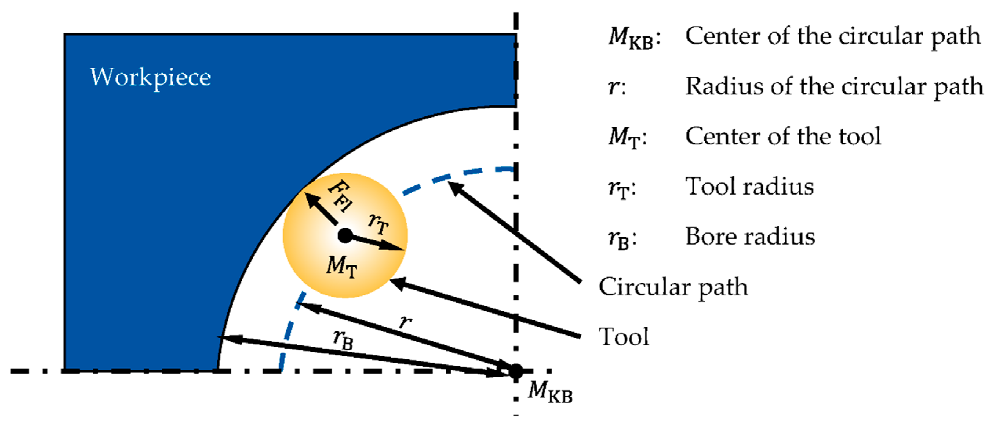
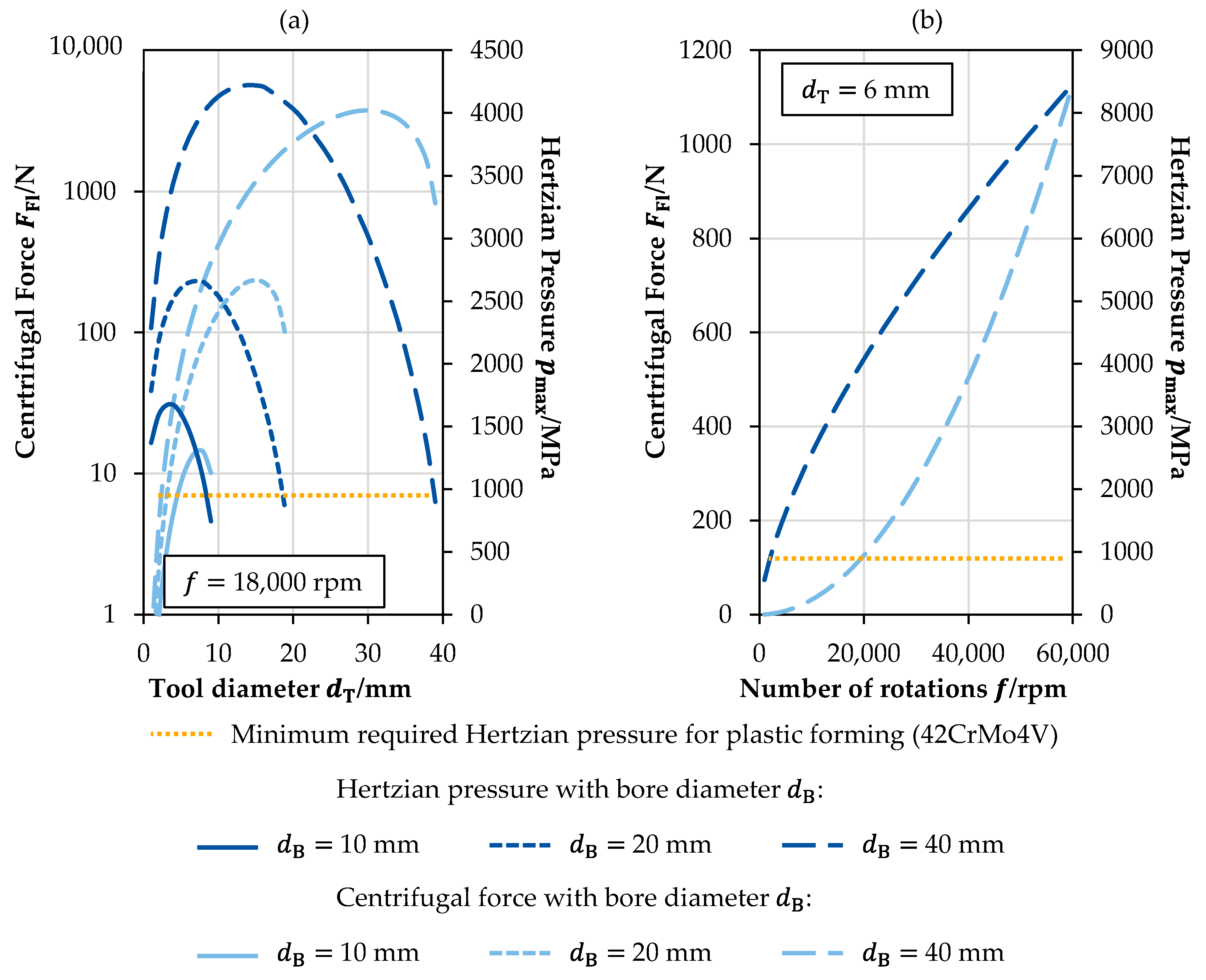
2. Process Force and Hertzian Pressure

The generation of force using the rotational speed of the spindle of the machining center is based on the utilization of the centrifugal force. The centrifugal force FFl is an inertia force and is calculated according to Equation (1) [7]:
FFl = m · ω2 · r = 4 · m · r · π2 · f2
Here, m is the mass of the body, ω the angular velocity, r the radius of the circular path on which the body moves and f the number of revolutions per second. The force acts radially outward from the center of the circular path. Figure 1 shows the schematic structure of a tool that uses the centrifugal force.
Assuming a spherical rolling element, the mass depends on the material density as well as on the volume. An increase in volume simultaneously increases the tool radius rT (Equation (3)) [7], which decreases the radius of the circular path. The relationship between the radius of the circular path r, the tool radius rT and the bore radius rB is shown in Equation (2). Accordingly, the centrifugal force FFl may be calculated using Equation (4).
r = rBrT
m = ρT · VT = 4/3ρT · π · rT3
FFl = 16/3ρT · π3 · rT3 · f2 · (rBrT)
The calculated theoretical process force does not directly indicate whether the surface is plastically formed since the contact area is not considered. Therefore, the maximum surface pressure in the form of the Hertzian pressure of a ball–cylinder contact according to KIRCHNER (neglecting plastic deformation) was calculated [8]. To maximize the centrifugal force, tungsten carbide was selected for the tool material due to its high density. The higher density results in a larger mass while maintaining the same ball volume, according to Equation (4), and therefore a higher centrifugal force. The parameters on which the calculation of the Hertzian pressure is based are listed in Table 1.
Figure 2a shows the Hertzian pressure pmax and the centrifugal force FFl as a function of the tool diameter dT for different bore diameters (dB = 10, 20 and 40 mm) for a rotational speed of f = 18,000 rpm. The speed was selected based on the maximum speed of the available machining center. In order to plastically form the surface area, a Hertzian pressure greater than the permissible dynamic Hertzian pressure pmax_zul is required. For a 42CrMo4V, this corresponds to pmax_zul_42CrMo4V = 980 MPa [8]. For all three bore diameters shown in Figure 2a, plastic forming is possible with a tool diameter of dT = 6 mm, neglecting losses such as friction. Accordingly, a tool with a diameter of 6 mm was selected in this work. Furthermore, a bore diameter of 40 mm was selected for the first tests in order to be able to compensate for any losses due to friction. Accordingly, Figure 2b shows the Hertzian pressure and the centrifugal force as a function of rotational speed for a bore diameter of dB = 40 mm and a tool diameter of dT = 6 mm. This shows that theoretically, neglecting losses, a Hertzian pressure of over pmax = 1000 MPa > pmax_zul_42CrMo4V is achieved starting from a rotational speed of f = 3000 rpm. Thus, plastic forming takes place for steels with a comparable or lower permissible dynamic Hertzian pressure than 42CrMo4V.
As mentioned, the forces and pressures calculated do not take into account the losses occurring during the real process. To ensure that the losses do not reduce the process forces and pressures below the necessary level, in the following, the experiments using a tool prototype are described in detail.

3. Materials and Methods

The theoretically calculated centrifugal force and the resulting Hertzian pressure described above indicate the possibility of using the rotational speed of the main spindle of a machining center for deep rolling. Nevertheless, the calculations do not consider losses such as friction losses during the process. Therefore, an experimental study was performed. In the following, the prototype to make use of the rotational speed of the spindle as well as the experimental setup are described. Afterwards, the experimental design is described.

3.1. Prototype of Centrifugal Deep Rolling Tool and Experimental Setup

Based on the results of the calculated force and Hertzian pressures, a bore diameter of dB = 40 mm and a tool diameter of dT = 6 mm were selected for the experimental investigation. The schematic representation of the tool (prototype) is shown in Figure 3a. For symmetry reasons, the tool has four bores for the carbide balls. Furthermore, it was ensured that the carbide balls could not roll onto the opposite side. For this purpose, the through bores have a diameter of dD = 5 mm. In the peripheral area, the bores are enlarged to a diameter of din = 7 mm (see Figure 3a). The tool has an internal coolant supply. This allows direct lubrication of the carbide balls as well as the possibility of hybrid force generation (centrifugal + hydrostatic). The tool was operated for the experiments in a Hermle C50 U machining center from HERMLE AG (Gosheim, Germany). The connection was realized by means of a collet chuck, see Figure 3b. The main spindle of the machining center has a maximum rotational speed of f = 18,000 rpm. In addition, an internal cooling lubricant supply with a maximum pressure of p = 80 bar is installed through the main spindle. The tests were carried out on workpieces made of 42CrMo4.

3.2. Experimental Design

The experimental design on which this work is based is listed in Table 2. The experimental plan aims at identifying different effects and possibilities of influence and does not claim to be complete. A total of four bores, two of which were blind bores and two of which were through bores, were processed. The first bore was used to identify whether forming was feasible. The second bore was used to identify the influence of different step-over distances on the roughness. The tests on the third bore were aimed at identifying the influence of the rotational speed on the roughness as well as the hardness. The second and third bores were also used to investigate whether external cooling is sufficient. The fourth bore was used to investigate the influence of different internal lubricant pressures on roughness and hardness.

3.3. Measurement Methods and Objectives

After the tests, the roughness was determined using a Hommel-Etamic T8000 from JENOPTIK AG (Jena, Germany) in accordance with DIN EN ISO 4288. The roughness was evaluated in the form of the average roughness depth Rz and the mean roughness Ra. In addition to the individual machined areas, comparative measurements were carried out on each bore at the unmachined area. For statistical validation, three measurements were carried out in each case and then averaged. The Vickers HV30 hardness was determined with the aid of a ZHU 250 hardness testing machine from ZWICKROELL AG (Ulm, Germany) in accordance with DIN EN ISO 6507. In accordance with the roughness measurements, the hardness tests were performed in triplicate for statistical assurance and the results were subsequently averaged. Furthermore, a visual evaluation of the surfaces was performed. Based on the visual evaluation, a qualitative evaluation of the processing fields was performed. The roughness measurements and hardness testing serve to quantify the effects between the process parameters and the surface area properties.

4. Results and Discussion

The results are divided into three parts. At first the visual evaluation is described, followed by the evaluation of the roughness measurements and the hardness tests.

4.1. Visual Evaluation

Figure 4 shows the test series 1 and 3 after machining as well as the decisive process parameters of the machining areas. In these two test series, the differences between the individual machining areas are most pronounced. Test series 1 initially served to investigate the possibility of achieving a sufficient process force with the aid of centrifugal force. Test 1.1 was used to identify the rotational speed range at which plastic deformation takes place. For this purpose, the rotational speed was successively increased in four steps up to n = 10,000 rpm. Between the individual steps, the machined path was evaluated visually. The results showed plastic deformation of the surface area starting at a rotational speed of n = 5000 rpm. At a rotational speed of n = 7500 rpm, the plastic deformation was pronounced. According to Figure 2, a maximum centrifugal force of FFl_5000 = 7.85 N (FFl_7500 = 17.67 N) and a Hertzian pressure of pmax_5000 = 1614 MPa (pmax_7500 = 2115 MPa) act at the rotational speeds. In test series 3, it is particularly noticeable that with increasing rotational speed or process force, the surface exhibits grooves that are not along the feed direction. A possible explanation is offered by the large clearance of the balls of sTool = 1 mm. The lack of guidance leads to a rapid deflection of the ball from the actual direction of movement.

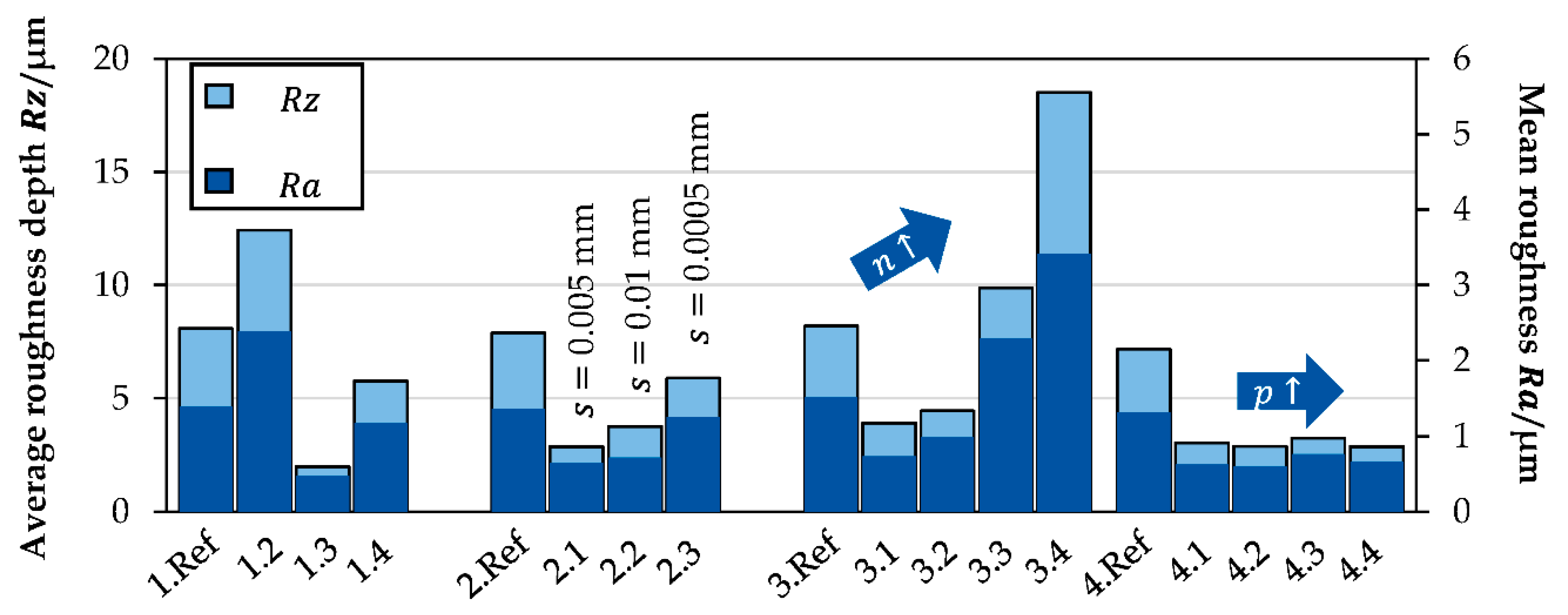
4.2. Roughness Measurements
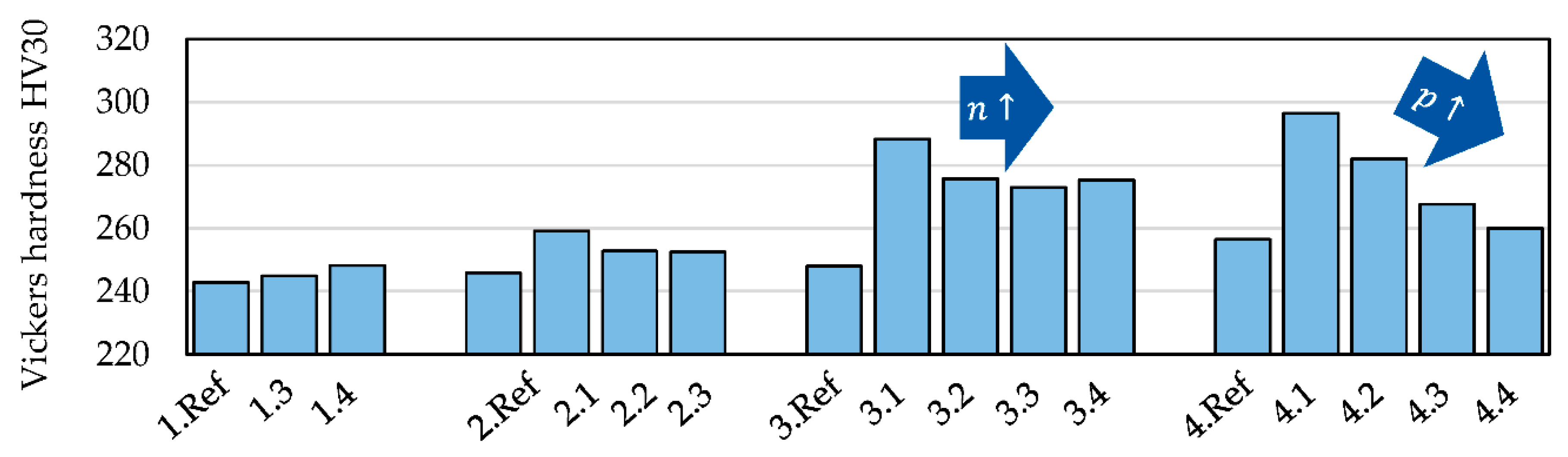
The results of the roughness measurements are shown in Figure 5. Test series 2 was used to investigate the influence of the step-over distance on the roughness. The results show a minimum roughness at a step-over distance of s = 0.005 mm. Both an increase to s = 0.01 mm and a reduction of the step-over distance to s = 0.0005 mm have a negative effect on the roughness. The increase in roughness with an increasing step-over distance is consistent with prior research and is explained by the reduced overlap. The increase in roughness with further reduction of the step-over distance may be due to soft kneading of the surface and the start of initial damage processes in the surface as a result of frequent over-rolling. Test series 3 was used to investigate the influence of rotational speed and thus of centrifugal force on roughness. In the process area under consideration, a higher rotational speed results in a deterioration of the roughness. This may be due to the greater accompanying plastic deformation and the large clearance of the machining ball described above. The results of test 1.3 with a rotational speed of n = 5000 rpm also confirm this behavior (cf. minimum rotational speed of test series 3: n = 7500 rpm). The influence of a superimposed internal lubricant pressure on the roughness was investigated on the basis of test series 4. The results indicate hardly any influence of the lubricant pressure. However, a possible explanation for this is that due to the use of a collet chuck (not sealed), the lubricant pressure set on the machine side is not present due to losses on the machining ball.

4.3. Hardness Tests

The results of the hardness tests are shown in Figure 6. Within test series 1 and 2 hardly any influence of the deep rolling on the hardness is observed. Since test series 3 and 4 show an increased hardness after deep rolling and test series 1, 2 differ especially in the bore type to test series 3 and 4, it is expected that test series 1 and 2 are influenced by the lubricant, which may not flow off. The physical context needs to be further investigated in future experiments. The evaluation of tests 3.3 and 3.4 proved to be difficult due to the high roughness and waviness of the surfaces and therefore showed a very high variation. Experiment 3.2 compared to 3.1 suggests that increased forces lead to a reduction in hardness increase. A possible explanation is the soft kneading of the surface. The results of test series 4 allow the conclusion that increased lubricant pressure is accompanied by a reduction in hardness increase. These results suggest that the greater lubricant pressure is accompanied by a significant increase in force, resulting in soft kneading of the surface area. With additional consideration of the roughness measurements, a stabilizing effect of the internal lubricant pressure is a possible explanation for reduced hardness, while roughness remains constant.

5. Conclusions

In deep rolling, hydraulic systems in particular are traditionally used to generate the process forces. For this purpose, additional units are usually necessary, since most machining centers or lathes cannot provide the necessary pressures. Within this research work, the fundamental suitability of centrifugal force for generating the process forces during the deep rolling of bores was investigated. First, it was shown that the theoretically occurring centrifugal forces with conventional machining centers are sufficient to plastically form metallic surfaces. This was then confirmed experimentally. Furthermore, the influence of the process parameters (step-over distance, rotational speed and lubricant pressure) on the roughness and hardness was investigated. It was shown that a reduction of the step-over distance initially has a positive effect on roughness, but a further reduction has a negative effect on the roughness as a result. In the rotational speed range considered, the lower the rotational speed, the lower the roughness. In addition, the results indicate that the lubricant pressure has a stabilizing effect on the process. To confirm this relationship, process force monitoring will be integrated in future work. In addition, a reduction of the clearance of the machining ball is planned, as well as an extensive investigation of the cause–effect relationships between the process parameters and the surface area properties.

Author Contributions

Conceptualization, L.U.; methodology, L.U.; formal analysis, I.F.W. and T.H.; investigation, L.U.; resources, T.H. and T.B.; data curation, L.U.; writing—original draft preparation, L.U.; writing—review and editing, L.U., I.F.W., T.H. and T.B.; visualization, L.U.; supervision, T.H. and T.B.; project administration, T.H. and T.B.; funding acquisition, T.B. All authors have read and agreed to the published version of the manuscript.

Funding

This research was funded by Germany’s Federal Ministry for Economic Affairs and Climate Action (BMWK, IGF Project No. 20407 N).

Institutional Review Board Statement

Not applicable.

Informed Consent Statement

Not applicable.

Data Availability Statement

Not applicable.

Acknowledgments

The authors would like to thank Felix Lambers for his great support during the experimental procedure.

Conflicts of Interest

The authors declare no conflict of interest.

References

  1. Lyubenova, N. Comprehensive Characterisation and Modelling of the Surface Integrity by Deep Rolling on Flat Surface. Ph.D. Thesis, Saarland University, Saarbrücken, Germany, 2020. [Google Scholar]
  2. Akkurt, A. Comparison of Roller Burnishing Method with Other Hole Surface Finishing Processes Applied on AISI 304 Austenitic Stainless Steel. J. Mater. Eng. Perform. 2011, 20, 960–968. [Google Scholar] [CrossRef]
  3. Schubnell, J.; Farajian, M. Fatigue improvement of aluminium welds by means of deep rolling and diamond burnishing. Weld. World 2021, 66, 699–708. [Google Scholar] [CrossRef]
  4. Muñoz-Cubillos, J.; Coronado, J.J.; Rodríguez, S.A. Deep rolling effect on fatigue behavior of austenitic stainless steels. Int. J. Fatigue 2017, 95, 120–131. [Google Scholar] [CrossRef]
  5. Ecoroll, A.G. Accessories for HG Tools: HGP Hydraulic Power Units. Available online: https://www.ecoroll.de/en/products/hydrostatic-tools/hgp-hydraulic-power-units.html (accessed on 11 July 2022).
  6. Types of Input and Output. Available online: https://mapal.com/en-us/products-and-solutions/actuating/types-of-input-and-output (accessed on 1 July 2022).
  7. Benenson, W. (Ed.) Handbook of Physics, 3rd ed.; Springer: New York, NY, USA; Berlin/Heidelberg, Germany, 2006. [Google Scholar]
  8. Kirchner, E. Leistungsübertragung in Fahrzeuggetrieben: Grundlagen der Auslegung, Entwicklung und Validierung von Fahrzeuggetrieben und deren Komponenten; Springer: Berlin/Heidelberg, Germany, 2007. [Google Scholar]
Figure 1. Schematic structure of a centrifugal force-based tool.
Engproc 26 00020 g001
Figure 2. Centrifugal force and Hertzian pressure for the contact between ball and cylinder, as shown in Figure 1, for dependence of the tool (ball) diameter (a) and the number of rotations (b).
Engproc 26 00020 g002
Figure 3. Schematic tool setup (a) and experimental setup in the machining center (b).
Engproc 26 00020 g003
Figure 4. Separated specimen after machining.
Engproc 26 00020 g004
Figure 5. Roughness after machining.
Engproc 26 00020 g005
Figure 6. Hardness results.
Engproc 26 00020 g006
Table 1. Parameters for the calculation of the Hertzian pressure.
PropertyUnitValue
Density of the tool material ρTg/cm314.9
Elastic modulus of the tool ETMPa630,000
Poission ratio of the tool νT-0.22
Elastic modulus of the workpiece EWMPa210,000
Poission ratio of the workpiece νW-0.3
Table 2. Experimental procedure.
Test NumberBore TypeLength of Test FieldStep-Over Distance
s/mm
Feed
fT/mm/min
Internal Lubricant Pressure
p/bar
Rotational Speed
n/1/min
1.1Blind000450–10,000
1.2Blind000155000
1.3Blind60.0015155000
1.4Blind80.001101510,000
2.1Blind60.00537.50 **7500
2.2Blind60.01750 **7500
2.3Blind60.00053.750 **7500
3.1Through60.00150 **5000
3.2Through60.0017.50 **7500
3.3Through60.001100 **10,000
3.4Through60.00112.50 **12,500
4.1Through60.0017.5157500
4.2Through60.0017.5307500
4.3Through60.0017.5457500
4.4Through60.0017.5607500
** external cooling used compare Figure 3a.
Publisher’s Note: MDPI stays neutral with regard to jurisdictional claims in published maps and institutional affiliations.

