Proceeding Paper

Response of Thin Sheet Metal on the Excitation in Electromagnetic Forming †

by
Björn Beckschwarte
1,*,
Lasse Langstädtler
1,2 and
Christian Schenck
1,2
1
Bremen Institute for Mechanical Engineering, University of Bremen, Badgasteiner Str. 1, 28359 Bremen, Germany
2
Mapex Center for Materials and Processing, P.O. Box 330440, 28334 Bremen, Germany
*
Author to whom correspondence should be addressed.
Presented at the 28th Saxon Conference on Forming Technology SFU and the 7th International Conference on Accuracy in Forming Technology ICAFT, Chemnitz, Germany, 2–3 November 2022.
Eng. Proc. 2022, 26(1), 4; https://doi.org/10.3390/engproc2022026004
Published: 2 November 2022

Abstract

:
Due to their low inertia, vibrations are stimulated during electromagnetic forming of thin sheets, whereby the excitation might involve the impact on the die and the oscillation of the electromagnetic forces. Depending on the configuration of the pulsed power generator and the resulting tool coil current, forced and free workpiece vibrations could be observed in experiments. The results indicate an influence of the vibrations on the springback behavior after thin sheet metal forming. Due to the workpiece vibration, the forming behavior changed. The results emphasize the need of designing pulsed power generators that adapt to the desired process.

1. Introduction

Electromagnetic forming enables the application of body forces for high speed forming. Based on this character, advantages can be achieved such as reduced springback [1] and reduced winkling [2], improved formability [3], or increased process flexibility [4]. These advantages have been considered mainly for the forming of thick sheet metal with a sheet thickness ≥ 1 mm [5]. Thus, process advantages from electromagnetic forming can be transferred to electromagnetic cutting [6] and joining [7].
The challenges of forming thin sheet metal or forming micro features [8] can be faced by electromagnetic forming. However, the amount of induced energy depends amongst others on the sheet thickness and the penetration depth of the electromagnetic field. Thibaudeau et al. identified an optimum ratio of workpiece thickness to penetration depth (skin depth) of the electromagnetic field of ≥0.66 [9]. If this ratio is decreased, the interaction of the electromagnetic field with the environment increases [10]. Accordingly, a subdivision of electromagnetic forming can be made into thick sheet metals with a thickness greater than the penetration depth and thin sheet metals with a thickness less than the penetration depth. In addition, force fluctuations by inhomogeneous tool coil [11] can appear. Further, process errors may occur such as the rebound effect [12] which is a result of the high speed impact of the workpiece on the die. In general, the distribution of the electromagnetic force and the workpiece speed influences the final geometry of the workpiece [13]. Therefore, not only the macro geometry is influenced, but also the micro geometry is changed by, e.g., multiple embossing [14].
In addition to the geometry, the ductility and fracture behavior are also changed by process-specific conditions during forming [15]. These conditions describe all states such as current flow during electromagnetic field induction or acceleration that the workpiece experiences during forming. Direct consequences for the process can be derived from these states. For example, current flow in the workpiece can lead to a locale workpiece evaporation [16]. Until now, workpiece vibrations could not be attributed to the process conditions. However, high-speed vibration can reduce springback [17], whereby the reduction is related to the amplitude of the workpiece vibration, which depends on the charge energy [18]. In this context, Yang et al. [19] determined for electromagnetic forming of thick-walled tubes that workpiece vibration is only based on elastic strain recovery. In general, vibration during forming changes the plastic properties and the material flow. A classification is made between the volume effect and the surface effect [20]. The surface effect primarily describes the change in friction conditions between the workpiece and the die. The volume effect describes the change in the plastic material properties. This effect is also known as Blaha-effect, which was firstly described in experiments with ultrasonic vibration by Blaha et al. [21]. According to Hu et al. [22], the volume effect can be described by three mechanisms: stress superposition, acoustic softening, and dynamic impact. These mechanisms are influenced substantially by the grain size [23]. In addition, the surface effects become more prominent with decreasing thickness of the workpiece by the higher surface to volume ration [20]. Thus, exciting workpiece vibration during forming could be a method for forming thin sheets, which are difficult to form due to low sheet thickness and low number of grains in the sheet thickness. In contrast to the usual method of vibrating the punch during forming, this work examines whether the electromagnetic force can be used for excitation. Therefore, the first step was to determine what kind of vibrations were present during electromagnetic forming. To identify the workpiece vibrations, the response to different excitations was determined using a photoelectric distance sensor. A variation of the excitation was done by adjusting the pulse power generator.

2. Methods

A sketch of the setup is shown in Figure 1a. A photoelectric sensor (LK-H157, Keyence, Osaka, Japan) was used to determine the forming height h of the workpiece. The measurement was performed in the center of the die cutout on the workpiece surface. The photoelectric sensor was operated in reflective mode and allowed the distance to be sampled every 2.55 µs. The Al99.5 workpiece (sheet thickness s0 = 100 µm, dimension of 50 × 50 mm²) were electromagnetically formed into a die (90MnCrV8) according to Figure 1b. A 60 mm long single-conductor tool coil made of copper with a cross-section of 5 × 5 mm² was used. The insulation between coil and workpiece was provided by means of 195 µm thick polymer foil. The workpiece and die were electrically connected. All experiments were repeated 3 times.
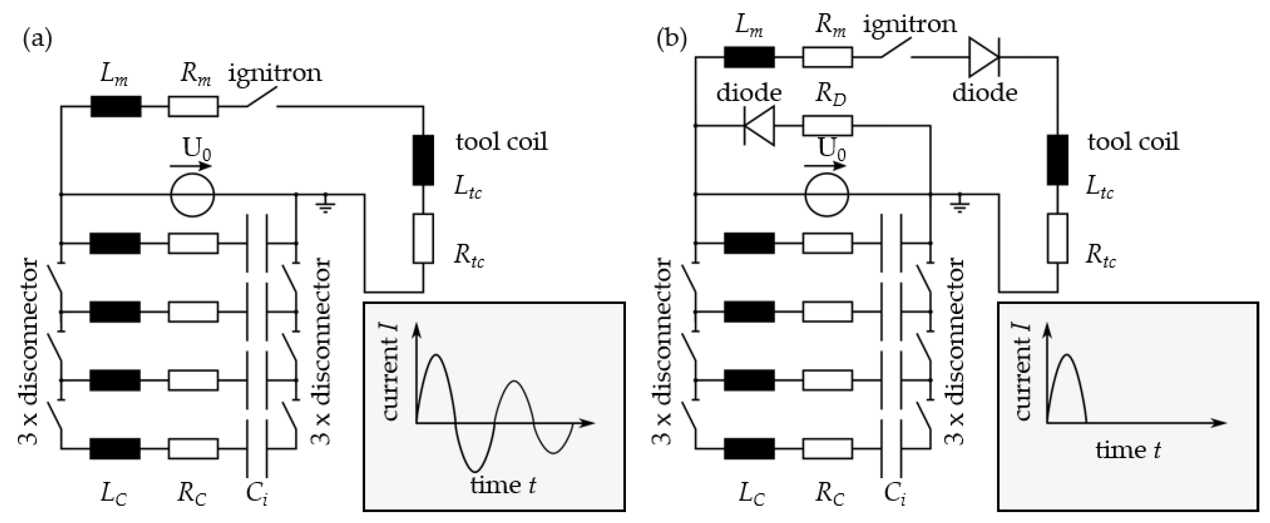
The experiments were carried out with a modular pulsed power generator, which consisted of 4 identical capacitors of Ci = 50 µF each (Series E62, ELECTRONICON Kondensatoren GmbH, Gera, Germany) (see Figure 2). The capacity C of the system could be adjusted by adding or separating the individual capacities Ci. This also caused a change in the inductance L of the entire system according to the individual inductances Li. The combination of inductance L and capacitance C results in the oscillation frequency f0 of the series resonant circuit in the pulse generator (see Equation (1)). Thus, the oscillation frequency f0 changed with the number of capacitors. The original configuration of 50 µF capacitance can be extended by a maximum of 3 additional capacitors with the disconnectors. The configurations 50 µF, 100 µF, and 200 µF were used. According to Equation 2, in addition to the change in the oscillation frequency f0, there is also a change in the charge energy Ec at a constant charge voltage U0. The experiments were performed with 1.5 kV, 2 kV, and 3 kV charge voltage U0.
f 0 = 1 2 × π × L × C
E C = 1 2 × C × U 0 2
Further, two different pulse generator configurations were used. In addition to oscillator configuration (Figure 2a), where the current freely oscillated, it was possible to prevent the tool coil current from oscillation during discharge by a diode (crowbar configuration, Figure 2b). The remaining energy was dissipated via resistor (RD). The tool coil current for both configurations was switched by an ignitron (NL8900, National Electronics, LaFox, Il, USA). The tool coil current was measured with a Rogowski coil (CWT300, Power Electronics Measurement Ltd., Nottingham, UK). All measurements were carried out with the same sampling frequency (fs = 392 kHz).
The time series of forming height h were analyzed in the frequency domain by fast Fourier transform-algorithm. The signal was processed after the main displacement of the workpiece (see Figure 3). The total length of the processed mean free signal was 1 ms, which resulted in a frequency resolution of 1 kHz. For comparability, the amplitudes Ah of the spectra were normalized to the individual maximum height amplitude Amax,h to receive the normalized height amplitude AN,h (see Equation (3)).
A N , h = A h A m a x , h
To identify the tool coil current oscillation, the signal was analyzed by the fast Fourier transform-algorithm. Therefore, the full length of the signal of 2 ms was used, which resulted in a frequency resolution of 0.5 kHz. Again, the current amplitudes AI of the spectrum were normalized to the individual maximum current amplitude Amax, to receive the normalized current amplitude AN,I (see Equation (4)).
A N , I = A I A m a x , I
To delimit a vibration of the workpiece from vibrations of the entire setup (rigid body motion), the frequency response of the setup shown in Figure 1 was determined. To acquire the system response, a DeltraTron® 4518 accelerometer (Hottinger Brüel and Kjaer GmbH, Darmstadt, Germany) was used. The sensor was placed on the photoelectric sensor so that the acceleration in forming direction (y-axis, see Figure 1) was detected. The system was excited by an impact hammer type 8206 (Hottinger Brüel and Kjaer GmbH, Darmstadt, Germany) with aluminum calotte. A Nexus conditioning amplifier type 2693 (Hottinger Brüel and Kjaer GmbH, Darmstadt, Germany) was used with a build in band pass filter of 1 Hz to 100 kHz. Excitation and system response were recorded with 100 kHz, whereby the signal length was 100 ms. Excitation with the impact hammer was performed in forming direction (y-axis, see Figure 1) and repeated 3 times. The signal of excitation and system response were transformed into the frequency domain by fast Fourier transform-algorithm. To compare the system response amplitude AS and the excitation amplitude AE both signals were normalized in the range of 0 kHz to 10 kHz to the maximum individual amplitude Amax,S/Amax,E to obtain the normalized system response AS,N and normalized excitation amplitude AE,N (see Equations (5) and (6)).
A S , N = A S A m a x , S
A E , N = A E A m a x , E

3. Results

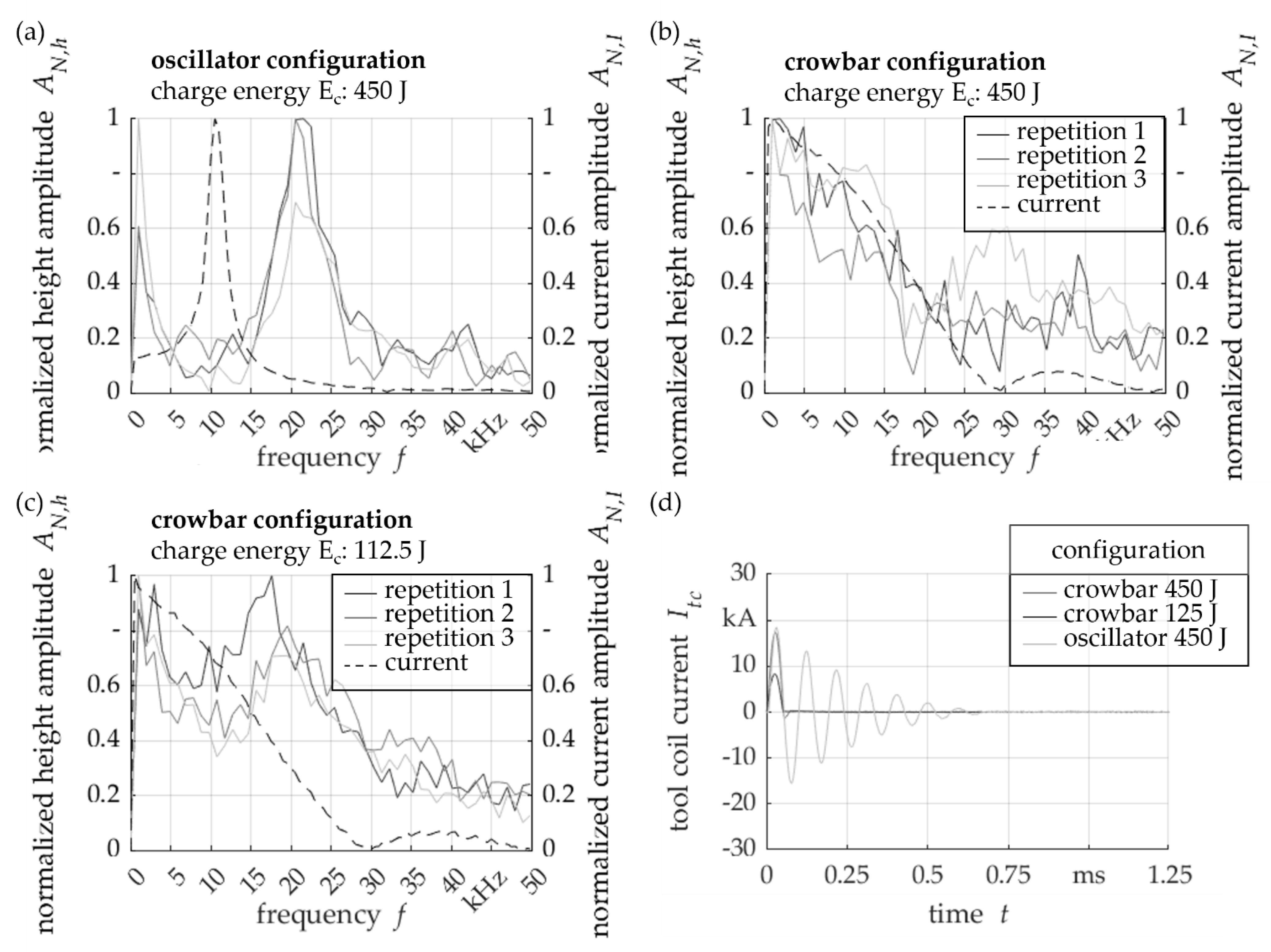
When the tool coil current was freely oscillating (oscillator configuration, see Figure 2a), the normalized height amplitude AN,h was high at about 1 kHz and at 21 kHz. The current oscillation featured a frequency of 10.5 kHz. As the resulting force is proportional to the tool coil current, the forming height oscillates at twice the frequency of the tool coil current. In this configuration, the free oscillation of the coil current results in a forced vibration of the workpiece. In crowbar configuration, where the tool coil current was actively suppressed (see Figure 4b), no significant vibration frequency of the workpiece could be determined. If the charge energy was reduced with crowbar configuration (see Figure 4c), a frequency of around 15–20 kHz arose, which may be considered to be the natural frequency of the workpiece. Comparable natural frequencies for the first mode were determined by simulation, whereby the influences of the formed geometry were not considered.
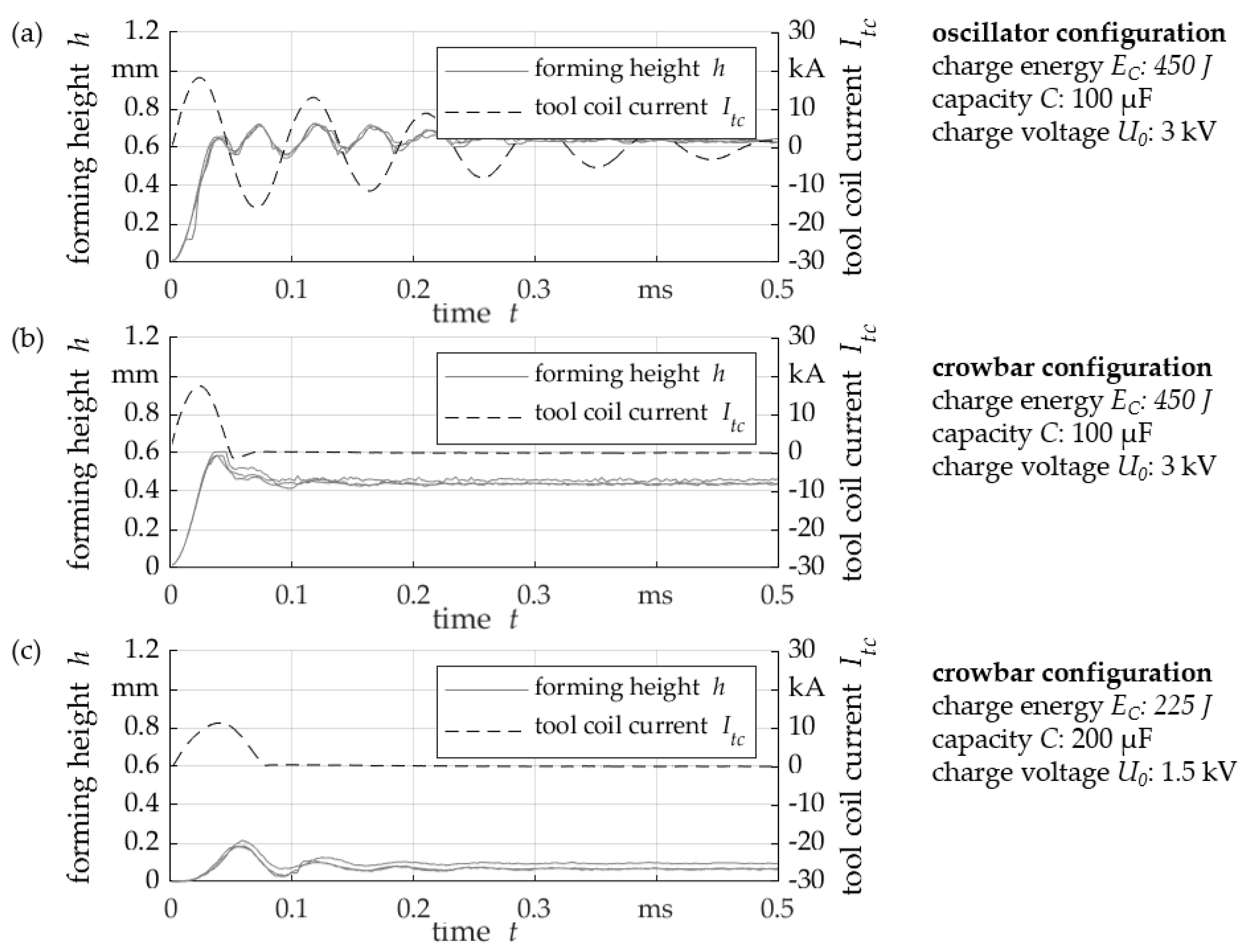
The comparison of the oscillator and crowbar configurations with same charge energy EC showed that the main forming section was similar and similar forming heights h were reached after the first rise (see Figure 5a,b). The subsequent vibration in the oscillator configuration vibrated around the remaining forming height h. In the case of the crowbar configuration, there was a shift directed towards the tool coil, which was superimposed by the workpiece vibration. This vibration may be influenced by the current, which was not completely suppressed by the configuration (see Figure 5b). However, the remaining forming height h was significantly reduced by around 0.2 mm. Therefore, the oscillations of the tool coil current contributed to the electromagnetic forming of thin sheets. Therefore, the forming height exceeded the remaining forming height h several times, so that an alternating strain occurred. As a result, the elastic-plastic behavior was changed by the tool coil current oscillation and springback was reduced with a remaining forming height h equal to the forming height h after the first rise.
When comparing the crowbar configuration (Figure 5b) with the crowbar configuration with reduced charging voltage U0 and thus reduced charging energy Ec (Figure 5c), the tool coil current Itc was completely suppressed. The reduction of the charge energy Ec lowered the forming height h, although the forming behavior remained comparable. Thus, after reaching the maximum forming height h, a workpiece vibration could be determined, vibrating with a frequency around 15 kHz. Similar vibration frequency of around 15–20 kHz had already been identified in Figure 4c. Thus, this frequency range may be considered as a range of natural frequencies, which was modified by the different forming height h of the workpiece. Accordingly, free workpiece vibration was the result with the crowbar configurations.
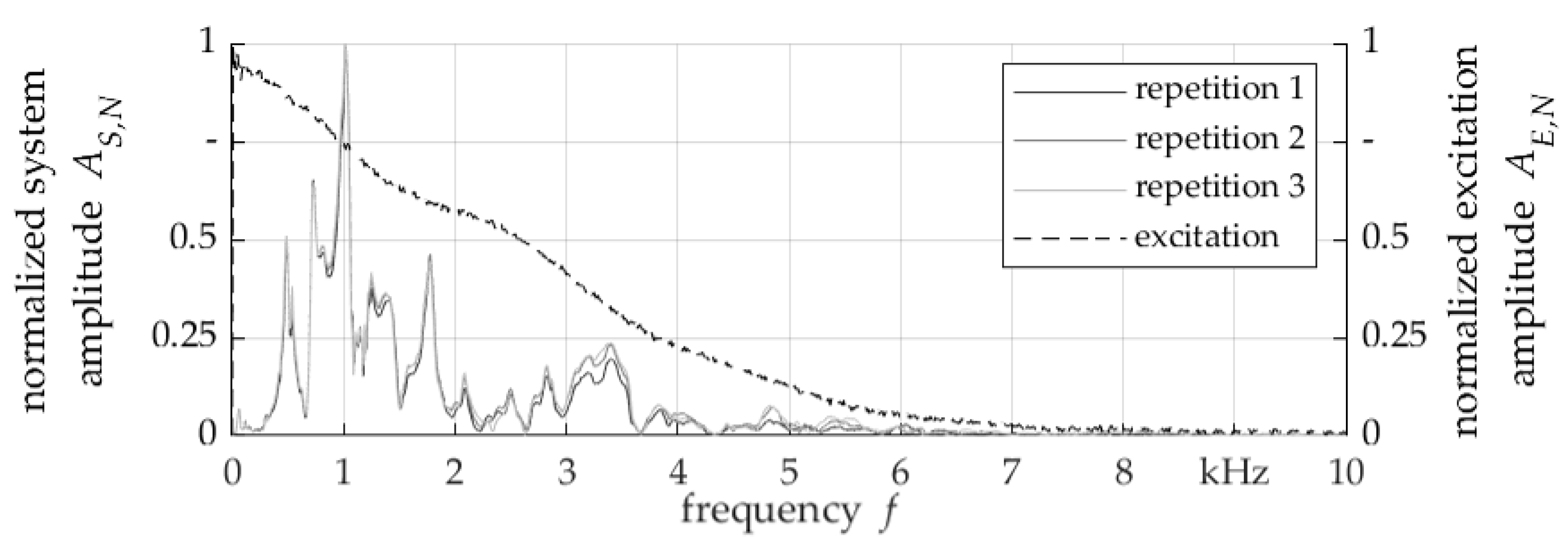
Excitation of the setup by impact hammer showed that a frequency excitation up to approximately 6.5 kHz was achieved (see Figure 6). The main amplitudes are in the range of about 1 kHz which fits to Figure 4a. Thus, the frequency of about 1 kHz determined in Figure 4 can be interpreted as the response of the entire experimental setup, hence a displacement between sensor and workpiece and not a vibration of the workpiece itself.
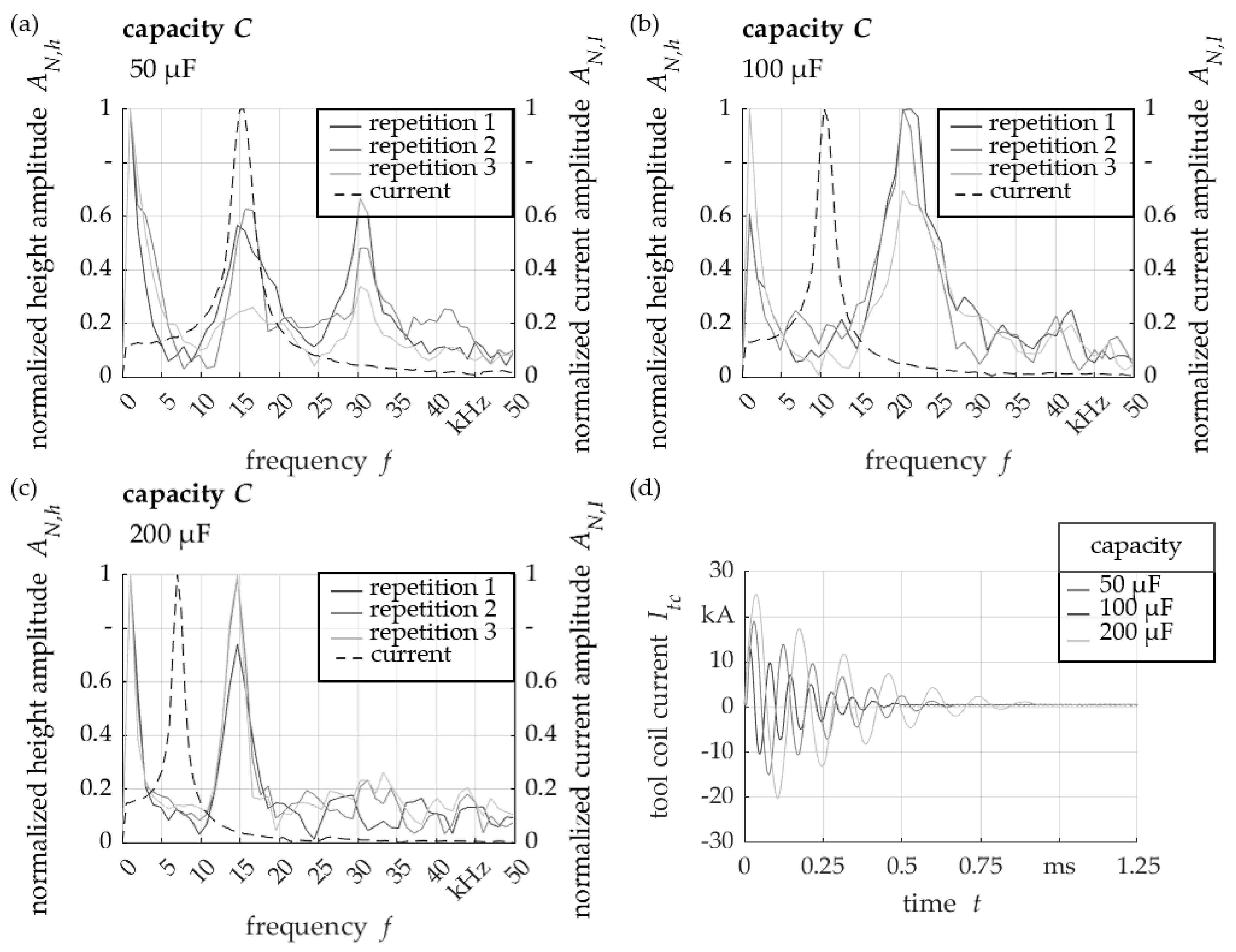
Using oscillator configuration with different capacity C led to different tool coil current oscillation frequency of 15 kHz, 10 kHz, and 7 kHz (see Figure 7). The vibration of the workpiece followed this change, whereby vibration frequencies of the workpiece of 31 kHz, 21 kHz, and 15 kHz could be determined. Again, the workpiece vibration fit to the electromagnetic force vibration.
As well as the 31 kHz vibration, a frequency of 16 kHz occurred when the experiments were conducted with a low capacity of 50 µF (see Figure 7a). The use of the 50 µF capacity configuration showed a reduced tool coil current amplitude and tool coil current flow duration in contrast to the larger capacities C (see Figure 7d). Due to this shortening of the forced vibration in combination with the lower amplitude, the elastic stress could not completely be relieved, so that a free vibration was enabled.

4. Discussion

Forced and free vibrations of the workpiece were identified in dependency of the oscillator configuration during the electromagnetic forming of thin sheets. Previous results for the electromagnetic forming of tubes showed only the existence of free vibrations [19], whereby these free vibrations in electromagnetic thin sheet metal forming required a crowbar configuration. The presence of forced vibrations can be attributed to the low inertia of the workpiece and the small displacements in the case of electromagnetic forming of thin sheets. These vibrations led to a changed elastic-plastic behavior and a reduction in springback of the aluminum workpieces. However, a further consequence from the occurrence of the different kinds of vibration cannot be estimated so far. As such, the dependence of the vibration on the electrical circuit and properties of the pulsed power generator offers the possibility to excite a desired vibration. Here, it must be noted that the positive influence on the material properties in previous work is based on a different ratio of process duration to vibration frequency. Furthermore, a further application of force must take place in the time range of the workpiece vibration. In addition, the impact of vibration in terms of process behavior and possible process defects must be clear before this opportunity can be used. Here, moreover, a consideration of the die-bound operations is to be made. Thus, a correlation between the multiple embossing process defects observed by Heidhoff et al. [14] and the forced workpiece vibration is to be expected. The crowbar configuration offers a process improvement as a possibility of the pulsed power technology, so that only a free vibration of the workpiece occurs. However, a reduction in forming height and greater springback must be taken into account. In addition to the crowbar configuration, it is worth testing whether sufficiently high tool coil current oscillation frequencies can be achieved by power generators that can generate multiple pulses within the effective processing time to manipulate and control the workpiece vibration.

5. Conclusions

In this work, the vibration behavior of the workpiece during electromagnetic forming was investigated and measured in physical experiments. Based on an oscillating tool coil current, a forced workpiece vibration was observed. This vibration was dependent on the characteristics of the pulsed power generator. By adjusting the pulsed power generator capacity, changing the workpiece vibration was possible. It has been shown that the tool coil oscillation changed the elastic-plastic behavior and therefore contributed to the remaining forming height and reduced the springback in electromagnetic forming. Furthermore, the forced oscillation was suppressed by adjusting the pulsed power generator. Hence, only a free oscillation of the workpiece remained.

Author Contributions

Conceptualization, B.B.; methodology, B.B.; software, B.B.; validation, B.B., L.L., and C.S.; formal analysis, B.B.; investigation, B.B.; resources, B.B.; data curation, B.B.; writing—original draft preparation, B.B., L.L., and C.S.; writing—review and editing, B.B., L.L., and C.S.; visualization, B.B.; supervision, L.L. and C.S.; project administration, L.L. and C.S.; funding acquisition, n/a. All authors have read and agreed to the published version of the manuscript.

Funding

This research was partially funded by the Deutsche Forschungsgemeinschaft (German Research Foundation DFG), grant number 395821503.

Institutional Review Board Statement

Not applicable.

Informed Consent Statement

Not applicable.

Data Availability Statement

Not applicable.

Conflicts of Interest

The authors declare no conflict of interest.

References

  1. Cui, X.; Zhang, Z.; Yu, H.; Xiao, X.; Cheng, Y. Springback Calibration of a U-Shaped Electromagnetic Impulse Forming Process. Metals 2019, 9, 603. [Google Scholar] [CrossRef] [Green Version]
  2. Noh, H.-G.; Song, W.-J.; Kang, B.-S.; Kim, J. Two-step electromagnetic forming process using spiral forming coils to deform sheet metal in a middle-block die. Int. J. Adv. Manuf. Technol. 2015, 76, 1691–1703. [Google Scholar] [CrossRef]
  3. Golovashchenko, S.; Imbert, J.M.; Worswick, M.J. Contributing Factors to the Increased Formability Observed in Electromagnetically Formed Aluminum Alloy Sheet. In Proceedings of the 2nd International Conference on High Speed Forming, Dortmund, Germany, 20–21 March 2006. [Google Scholar] [CrossRef]
  4. Carson, B.; Daehn, G.; Psyk, V.; Tekkaya, A.E.; Weddeling, C.; Woodward, S. Agile Production of Sheet Metal Aviation Components Using Disposable Electromagnetic Actuators. In Proceedings of the 4th International Conference on High Speed Forming, Columbus, OH, USA, 9–10 March 2010. [Google Scholar] [CrossRef]
  5. Psyk, V.; Risch, D.; Kinsey, B.L.; Tekkaya, A.E.; Kleiner, M. Electromagnetic forming—A review. J. Mater. Process. Technol. 2011, 211, 787–829. [Google Scholar] [CrossRef]
  6. Maier-Komor, P.; Hoffmann, H.; Ostermair, M. Cutting of hollow profiles using electromagnetic fields. Int. J. Mater. Form. 2010, 3, 503–506. [Google Scholar] [CrossRef]
  7. Aizawa, T.; Kashani, M.; Okagawa, K. Application of magnetic pulse welding for aluminum alloys and SPCC steel sheet joints. Weld. J. 2007, 86, 119–124. [Google Scholar]
  8. Geiger, M.; Kleiner, M.; Eckstein, R.; Tiesler, N.; Engel, U. Microforming. CIRP Ann. 2001, 50, 445–462. [Google Scholar] [CrossRef]
  9. Thibaudeau, E.; Kinsey, B.L. Analytical design and experimental validation of uniform pressure actuator for electromagnetic forming and welding. J. Mater. Process. Technol. 2015, 215, 251–263. [Google Scholar] [CrossRef]
  10. Beckschwarte, B.; Langstädtler, L.; Schenck, C.; Herrmann, M.; Kuhfuss, B. Numerical and Experimental Investigation of the Impact of the Electromagnetic Properties of the Die Materials in Electromagnetic Forming of Thin Sheet Metal. J. Manuf. Mater. Process 2021, 5, 18. [Google Scholar] [CrossRef]
  11. Golowin, S.; Kamal, M.; Shang, J.; Portier, J.; Din, A.; Daehn, G.S.; Bradley, J.R.; Newman, K.E.; Hatkevich, S. Application of a Uniform Pressure Actuator for Electromagnetic Processing of Sheet Metal. J. Mater. Eng. Perform. 2007, 16, 455–460. [Google Scholar] [CrossRef]
  12. Risch, D.; Vogli, E.; Baumann, I.; Brosius, A.; Beerwald, C.; Tillmann, W.; Kleiner, M. Aspects of Die Design for the Electromagnetic Sheet Metal Forming Process. In Proceedings of the 2nd International Conference on High Speed Forming, Dortmund, Germany, 20–21 March 2006. [Google Scholar] [CrossRef]
  13. Imbert, J.; L’Eplattenier, P.; Worswick, M. Effects of Force Distribution and Rebound on Electromagnetically Formed Sheet Metal. In Proceedings of the 4th International Conference on High Speed Formin, Columbus, OH, USA, 9–10 March 2010. [Google Scholar] [CrossRef]
  14. Heidhoff, J.; Beckschwarte, B.; Riemer, O.; Schönemann, L.; Herrmann, M.; Schenck, C.; Kuhfuss, B. Electromagnetic Embossing of Optical Microstructures with High Aspect Ratios in Thin Aluminum Sheets. In Proceedings of the 24th International Conference on Material Forming (ESAFORM 2021), Liège, France, 14–16 April 2021. [Google Scholar] [CrossRef]
  15. Ma, H.; Huang, L.; Wu, M.; Li, J. Dynamic Ductility and Fragmentation for Aluminum Alloy Using Electromagnetic Ring Expansion. Procedia Eng. 2014, 81, 787–792. [Google Scholar] [CrossRef] [Green Version]
  16. Langstädtler, L. Elektromagnetisches und Elektrohydraulisches Umformen in der Mikroproduktion. Ph.D. Thesis, University of Bremen, Bremen, Germany, 2020. [Google Scholar] [CrossRef]
  17. Du, Z.; Yan, Z.; Cui, X.; Chen, B.; Yu, H.; Qiu, D.; Xia, W.; Deng, Z. Springback control and large skin manufacturing by high-speed vibration using electromagnetic forming. J. Mater. Process. Technol. 2022, 299, 117340. [Google Scholar] [CrossRef]
  18. Xia, W.; Cui, X.; Du, Z.; Deng, Z.; Lin, Y. Springback control with small vibration using electromagnetic forming. Int. J. Adv. Manuf. Technol. 2022, 118, 3133–3145. [Google Scholar] [CrossRef]
  19. Yang, K.; Taber, G.; Sapanathan, T.; Vivek, A.; Daehn, G.S.; Raoelison, R.N.; Buiron, N.; Rachik, M. Development of Vibration During the Electromagnetic Ring Expansion Test. In Proceedings of the 7th International Conference on High Speed Forming, Dortmund, Germany, 27–28 April 2016. [Google Scholar] [CrossRef]
  20. Zhai, J.; Guan, Y.; Li, Y.; Liu, Y.; Lin, J. The surface effect of ultrasonic vibration in double cup extrusion test. J. Mater. Process. Technol. 2022, 299, 117344. [Google Scholar] [CrossRef]
  21. Blaha, F.; Langenecker, B. Dehnung von Zink-Kristallen unter Ultraschalleinwirkung. Naturwissenschaften 1955, 42, 556. [Google Scholar] [CrossRef]
  22. Hu, J.; Shimizu, T.; Yang, M. Investigation on ultrasonic volume effects: Stress superposition, acoustic softening and dynamic impact. Ultrason. Sonochem. 2018, 48, 240–248. [Google Scholar] [CrossRef] [PubMed]
  23. Ahmadi, F.; Farzin, M.; Mandegari, M. Effect of grain size on ultrasonic softening of pure aluminum. Ultrasonics 2015, 63, 111–117. [Google Scholar] [CrossRef] [PubMed]
Figure 1. Experimental setup: (a) sketch of the setup (b) drawing of the die.
Engproc 26 00004 g001
Figure 2. Pulsed power generator: (a) oscillator configuration, (b) crowbar configuration.
Engproc 26 00004 g002
Figure 3. Definition of the processed interval of the forming height h signal and the measured tool coil current Itc.
Engproc 26 00004 g003
Figure 4. Forming height and tool coil current oscillations: (a) oscillator configuration (EC = 450 J), (b) crowbar configuration (EC = 450 J), (c) crowbar configuration (EC = 112.5 J), (d) tool coil current in time domain.
Engproc 26 00004 g004
Figure 5. Forming height h in time domain for different configurations and different charge energy values: (a) oscillator configuration (EC = 450 J), (b) crowbar configuration (EC = 450 J), (c) crowbar configuration (EC = 225 J).
Engproc 26 00004 g005
Figure 6. System response of the setup based on the excitation with an impact hammer.
Engproc 26 00004 g006
Figure 7. Effect of different capacity C on the workpiece vibration for charge voltage U0 = 3 kV: (a) capacity C = 50 µF, (b) capacity C = 100 µF, (c) capacity C = 200 µF, (d) resulting tool coil current Itc.
Engproc 26 00004 g007
Publisher’s Note: MDPI stays neutral with regard to jurisdictional claims in published maps and institutional affiliations.