Proceeding Paper

Motion Planning of a Triple-Link Robotic System †

Wolfson Centre for Magnetics, School of Engineering, Cardiff University, Cardiff CF24 3AA, UK
*
Author to whom correspondence should be addressed.
Presented at the 3rd International Electronic Conference on Applied Sciences, 1–15 December 2022; Available online: https://asec2022.sciforum.net/.
Eng. Proc. 2023, 31(1), 48; https://doi.org/10.3390/ASEC2022-13774
Published: 1 December 2022
(This article belongs to the Proceedings of The 3rd International Electronic Conference on Applied Sciences)

Abstract

:
The Robogymnast is a complex system formed from a triple-inverted pendulum and mimics the action of a gymnast as they hang by their hands from a high bar and perform progressive upswings to eventually rotate completely around the bar. The three links of the Robogymnast can be compared to the lower limbs, the torso, and the upper limbs of a gymnast, with a single passive joint and two further stepper-motor powered joints. There is sensor equipment attached to the different links to gather data and control signals. While this system has been physically constructed, the current paper describes the approach to automating the 3-link pendulum and describes the system, its parts and setup. Following this, STM32 is applied for programming, system operation and presentation of results.

1. Introduction

The Robogymnast was chosen to represent a complex, underactuated multiple-link mechanical system in order to evaluate and compare control systems based on a range of methods [1]. Designing a control system with underactuation presents challenges because full-state feedback linearisation around a fixed point of equilibrium is often not possible for this type of mechanism, which is also frequently not small-time local controllable (STLC) [2].
This has led to considerable research interest in developing an underactuated system in the fields of control engineering and robotics [3]. Inverted pendulums involve a component which swings freely from a fixed location, and it is suspended under the action of gravitational forces. Work involving regulating movement frequently uses this type of mechanism, and both hybrid and chaotic systems can be demonstrated using this approach [4,5]. An important robotics challenge is presented by the problem of balancing triple-inverted pendulum systems, and this is based on their similarity to the structural and balance factors of the human body. The Acrobat is a robotic system that mimics acrobatic activity in humans, has an inverted pendulum form, and is designed to have instability and underactuation. This makes the robot ideal for theory- and practice-based work on non-linear controls [3,6]. The Acrobat was designed to balance using a specially developed, intelligent controller, which blended conventional control, fuzzy control and adaptive fuzzy control in order to achieve swing, catch and balance in inversion [7]. The controllers tested were based on state variable feedback, as well as proportional-integral-derivative and linear-quadratic regulation approaches.

2. Related Work

The studies presented in [8,9,10,11,12] focus on autonomous upswing for triple-link robots with a single non-actuated joint and two actuated joints. The contribution of this study is to assess movement performance across three links. Such multiple-link inverted pendulum-based systems have various real-world contributions:
-
Such systems can contribute to research investigating problems of movement for disabled or injured individuals, who do not have full use of their arms or legs [13].
-
If such systems could be effectively controlled through the exploitation of the dynamic properties within them, machines could be developed that are more energy efficient and move more smoothly in line with natural moving systems [14] Other studies previously conducted have examined how stability can be achieved in multiple-link robotic systems using a swing mechanism through examining various types of controllers, including Linear–quadratic regulator (LQR) [15], proportional–integral–derivative controller (PID) [16], fuzzy proportional–derivative controller FPD [17], and Fuzzy proportional–integral–derivative controller (FLQR) [18].
The current work makes an original contribution to these issues by implementing and making comparisons between the varied movements found in a 3-link robot across each of the three links. In addition, it presents a new approach to controlling the movement of the pendulum system through synchronising, and it investigates the performance of the stepper motor.
This paper is structured in the following way: the second section provides an overview of related work that have been previously conducted, while the third section first describes the system in general and then discusses its setup further. In Section 4, the results for the motion across each link are examined under various conditions, and the final section provides a summary of the research and presents the conclusions.

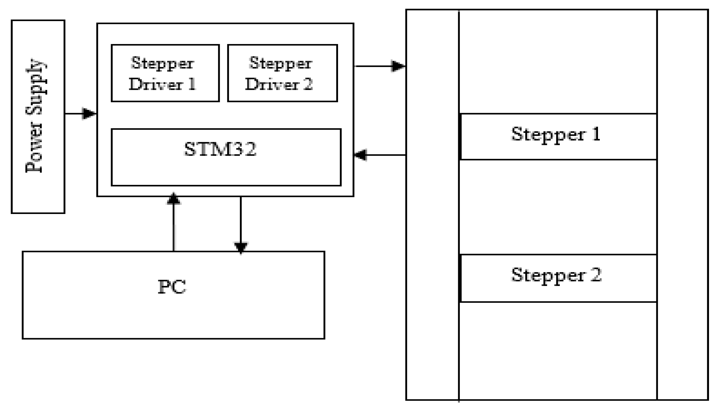
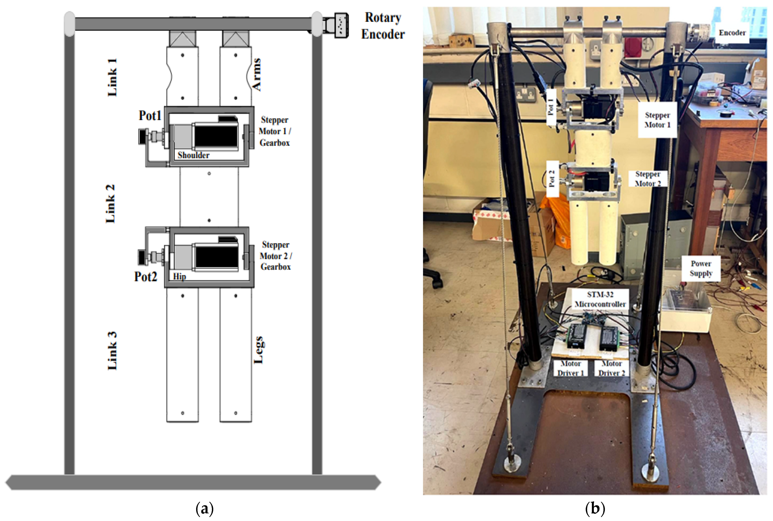
3. System Description and Setup

3.1. System Description

This work is applied to a triple-link Robogymnast mechanism, which imitates the gymnastic action of swinging up to freely rotate over a high bar. The diagram given in Figure 1 illustrates the system’s major components, in which the first link is representative of the upper limbs of a gymnast (without modelling the joints at the elbow and wrist); link 2 relates to the head and trunk, as one component without different joints; and link 3 corresponds to the legs, with no joints for the knees and ankles. The Robogymnast’s first joint is unactuated, using passive action, while the remaining two joints, which can be related to a gymnast’s shoulder and hip joints, are active in their operation [13]. Figure 2 illustrates the robotic system through a block diagram, in which it is operates via two stepper motors, with each being subjected to the stepper driver control to achieve smooth movement. The control system programming is performed through the microcontroller STM32 using C++ language for translating commands between the robotic system, the control system and the PC. Each link has its own sensor, and link 1 connects to a rotary encoder, with the remaining links connecting to the potentiometers 2 and 3, respectively, to allow for the detection of absolute angles across every position [15]. Table 1. illustrates the Robogymanst parameters in order to length, weight, and angles.

3.2. System Setup

This section considers the setup of the system, where the system itself is attached by connecting to joints 2 and 3 with dual potentiometers as the sensors, and then the header connects with the encoder to detect the absolute value of motion. On the other hand, the operating system, as shown in Figure 1, contains 2 stepper drivers powered by 5v along with programming by an STM-32 microcontroller connecting to a PC to instruct the movement of the system and to read the signal returned from the sensors. Lastly, Figure 2a,b display the Robogymnast’s design diagram and an actual system prepared to run.

4. Results

Discussion

Figure 3a–c demonstrate that each link is in motion simultaneously, in which theta 1 represents the t2 (stepper 1) and t3 (stepper 2) response, based on the opposing motion of the two motors. The second joint is operated by stepper 1, and if it moves in the positive direction, stepper 3 then moves in the opposite direction. In addition to this, the bottom link, which is link 3, is operated by stepper 2, and this begins to reverse at the point when the first motor moves forward, beginning the movements towards upswing of the robot in this system. Based on this, Table 2 provides the estimated values for the degree of motion in the multiple-link mechanism in both scenarios when, on average, the maximum points in both directions are positive and negative (forward and backward).

5. Conclusions

In this work, planned movement for upswing in a 3-link inverted pendulum-based robot is presented. A description is given of how this system was set up, considering the connection of each component of the system. Subsequent studies will examine this movement further and consider how this 3-link system can be modulated for upswing, as well as developing the controller further for optimisation of the algorithms and their implementation in future work.

Author Contributions

Conceptualization, B.A.S. and M.M.; methodology, B.A.S. and F.A.; software, B.A.S. and M.M.; validation, B.A.S. and M.M.; formal analysis, B.A.S. and F.A.; investigation, B.A.S. and M.M.; resources, B.A.S. and F.A.; data curation, B.A.S. and M.M.; writing—original draft preparation, B.A.S. and F.A.; writing—review and editing, B.A.S. and F.A.; visualisation, B.A.S. and M.M.; supervision, B.A.S. and F.A.; project administration, F.A.; funding acquisition, B.A.S. All authors have read and agreed to the published version of the manuscript.

Funding

This paper is part of the research of the corresponding author, B.A.S., who is sponsored by the Ministry of Higher Education and Scientific Research in Libya.

Institutional Review Board Statement

Not applicable.

Informed Consent Statement

Not applicable.

Data Availability Statement

Not applicable.

Acknowledgments

The authors would like to thank Cardiff University/School of Engineering and the Ministry of Higher Education in Libya for their support.

Conflicts of Interest

The authors declare no conflict of interest.

References

  1. Ismail, H.; Eldhukhri, E.; Packianather, M.S. Invasive weed optimization of swing-up control parameters for robot gymnast. In Proceedings of the 2014 IEEE/ASME International Conference on Advanced Intelligent Mechatronics, Besacon, France, 8–11 July 2014. [Google Scholar]
  2. Lai, X.; Wu, M.; She, J.; Zhang, A. Motion control of underactuated three-link gymnast robot based on combination of energy and posture. IET Control Theory Appl. 2011, 5, 1484–1493. [Google Scholar] [CrossRef]
  3. Muskinja, N.; Tovornik, B. Swinging up and stabilization of a real inverted pendulum. IEEE Trans. Ind. Electron. 2006, 53, 631–639. [Google Scholar] [CrossRef]
  4. Spong, M. The swing up control problem for the Acrobot. IEEE Control Syst. 1995, 15, 49–55. [Google Scholar]
  5. Medrano-Cerda, G.A.; Eldukhri, E.E.; Cetin, M. Balancing and Attitude Control of Double and Triple Inverted Pendulums. Trans. Inst. Meas. Control 1995, 17, 143–154. [Google Scholar] [CrossRef]
  6. Lakshmi, K. Design of Robust Energy Control for Cart-Inverted Pendulum. Int. J. Eng. Technol. 2007, 4, 66–76. [Google Scholar]
  7. Brown, S.; Passino, K.M.K. Intelligent Control for an Acrobat. J. Intell. Robot. Syst. Theory Appl. 1997, 18, 209–247. [Google Scholar] [CrossRef]
  8. Eldukhri, E.; Pham, D.T. Autonomous Swing-Up Control of a Three-Link Robot Gymnast. Proc. Inst. Mech. Eng. Part I J. Syst. Control. Eng. 2010, 224, 825–832. [Google Scholar] [CrossRef]
  9. Kamil, H.; Eldukhri, E.; Packianather, M. Balancing Control of Robot Gymnast Based on Discrete-Time Linear Quadratic Regulator Technique. In Proceedings of the 2014 2nd International Conference on Artificial Intelligence, Modelling and Simulation, Madrid, Spain, 18–20 November 2014. [Google Scholar]
  10. Eldukhri, E.E.; Kamil, H.G. Optimisation of swing-up control parameters for a robot gymnast using the Bees Algorithm. J. Intell. Manuf. 2013, 26, 1039–1047. [Google Scholar] [CrossRef]
  11. Ismail, H.A.; Packianather, M.S.; Grosvenor, R.I. Multi-objective invasive weed optimization of the LQR controller. Int. J. Autom. Comput. 2017, 14, 321–339. [Google Scholar] [CrossRef]
  12. Mohamed, M.; Samad, B.A.; Anayi, F.; Packianather, M. Analysing Various Control Technics for Manipulator Robotic System (Robogymnast). Comput. Mater. Contin. 2023, in press. [Google Scholar]
  13. Ismail, H.A. Intelligent Model-Based Control of Complex Multi-Link Mechanisms. Ph.D. Thesis, Cardiff University, Cardiff, UK, December 2016. [Google Scholar]
  14. Kamil, H.G. Intelligent Model-Based Control of Complex Three-Link Mechanisms. Ph.D. Thesis, Cardiff University, Cardiff, UK, April 2015. [Google Scholar]
  15. Samad, B.A.; Anayi, F.; Melikhov, Y.; Mohamed, M.; Altayef, E. Modelling of LQR and Fuzzy-LQR Controllers for Stabilisation of Multi-link Robotic System (Robogymnast). In Proceedings of the 2022 8th International Conference on Automation, Robotics and Applications (ICARA), Prague, Czech Republic, 18–20 February 2022. [Google Scholar]
  16. Mohamed, M.; Anayi, F.; Packianather, M.; Samad, B.A.; Yahya, K. Simulating LQR and PID controllers to stabilise a three-link robotic system. In Proceedings of the 2022 2nd International Conference on Advance Computing and Innovative Technologies in Engineering (ICACITE), Greater Noida, India, 28–29 April 2022. [Google Scholar]
  17. Samad, B.A.; Mohamed, M.; Anayi, F.; Melikhov, Y. A hybrid Fuzzy approach of different controllers to stabilize a 3-link swinging robotic (Robogymnast). In Proceedings of the 2022 2nd International Conference on Advance Computing and Innovative Technologies in Engineering (ICACITE), Greater Noida, India, 28–29 April 2022. [Google Scholar]
  18. Samad, B.A.; Mohamed, M.; Anayi, F.; Melikhov, Y. An Investigation of Various Controller Designs for Multi-Link Robotic System (Robogymnast). Knowledge 2022, 2, 465–486. [Google Scholar] [CrossRef]
Figure 1. Robogymnast operation system.
Engproc 31 00048 g001
Figure 2. (a) Robogymnast diagram; and (b) Robogymnast system.
Engproc 31 00048 g002
Figure 3. (a) Upper link free rotate; (b) middle link (stepper motor 1); and (c) lower link (stepper 2).
Engproc 31 00048 g003
Table 1. Robogymnast parameters.
SymbolParametersMean Value
L1Length of 1st link0.16 m
L2Length of the middle link (link 2)0.18 m
L3Length of lower link (link 3)0.24 m
m1Weight of link 11.2 kg
m2Weight of link 21.2 kg
m3Weight of lower link 30.5 kg
q1, q2, q3Angles’ initial values0 (rad)
gGravity9.81 m/s2
Table 2. Robogymnast motion results.
SymbolParametersAverage (Degrees)°Max Point
(Degrees)°
θ1Link 1 (free rotate) upper(−5) to 25(−45) to 80
θ2Link 2 (Motor 1) middle(−5) to 15(−45) to 25
θ3Link 3 (Motor 3) lower(−10) to 10(−35) to 35
Disclaimer/Publisher’s Note: The statements, opinions and data contained in all publications are solely those of the individual author(s) and contributor(s) and not of MDPI and/or the editor(s). MDPI and/or the editor(s) disclaim responsibility for any injury to people or property resulting from any ideas, methods, instructions or products referred to in the content.

