Proceeding Paper

Investigation of Internal Model for Unmanned Vehicle Control in Case of Its Aggressive Motion along a Spatial Trajectory †

1
Federal Research Center “Computer Science and Control”, Russian Academy of Sciences, 44 bld. 2, Vavilova Str., 119333 Moscow, Russia
2
Engineering Academy, RUDN University, 6 Miklukho-Maklaya St., 117198 Moscow, Russia
*
Author to whom correspondence should be addressed.
Presented at the 15th International Conference “Intelligent Systems” (INTELS’22), Moscow, Russia, 14–16 December 2022.
Eng. Proc. 2023, 33(1), 38; https://doi.org/10.3390/engproc2023033038
Published: 20 June 2023
(This article belongs to the Proceedings of 15th International Conference “Intelligent Systems” (INTELS’22))

Abstract

:
The work is devoted to the study of methods that are used to control the movement of an object along a given trajectory. A control method involving an accurate internal model is proposed. This internal model was built on the basis of the object’s mathematical model and real object, performed by artificial neural networks. For a limited period of time the model is able to determine the object state without surveillance system usage. The dynamic model of an unmanned vehicle was obtained by method developed at the Robotics Center of the FRC CSC RAS. This method acquires experimental data and performs model identification by means of a neural network. The trajectory is a set of spatial points generated by the developed real unmanned vehicle simulator. The control was carried out on the basis of PID-controller and model predictive control method. The comparison of control methods for a real and virtual unmanned vehicles was conducted in the simulator developed. The results of field experiments, during which control by internal model was applied, are presented.

1. Introduction

Unmanned vehicles control from the initial state to the final one should meet the desired quality requirements. At the same time, it is necessary to synthesize such control laws that ensure the achievement of the control goal in the wide class of the uncertainty of vehicle’s dynamics. To synthesize the required control laws, the unmanned vehicles control system simulation should be performed. A mathematical model of a real system can be obtained with the help of well-known identification methods [1,2]. Herein the following system identification methods are used, ARMAX (autoregressive moving average models with exogenous inputs) and NARMAX (non-linear ARMAX). These methods allow to obtain linear and non-linear polynomial functions that model the relationship between the perception of the robot sensor and its motor response. These methods are extended to neural network structures [3] and are successfully applied to non-linear unmanned vehicles.
One of the approaches in the field of unmanned mobile systems, such as unmanned vehicles operating in automatic mode, is aimed at the development of non-linear control laws for real time trajectories tracking [4,5,6].
Unmanned vehicles’ real-time trajectory control is usually divided into three sub-tasks, trajectory generation, position determination, and trajectory tracking.
This paper presents the results of model identification of a real unmanned vehicle. Kinematic equations of unmanned vehicle describe mass center position ( x , y ) and direction of movement ( θ ) . These parameters depend on linear velocity ( v ) and rotation angle of front wheels ( α ) . Unmanned vehicle and its kinematic movement control scheme are presented in Figure 1.
Artificial neural networks belong to modern model identification methods used in robotics. Combined with differential equations, ANNs provide satisfying results in real non-linear dynamics systems identification.
The article presents a formal statement of the model identification problem. A universal strategy for its solution that uses ANNs is proposed. The obtained model, or so-called the internal one, is applied in a special simulator developed to automate path generation and the process of obtaining the state of the unmanned vehicle that is conducted in selected control methods in case of some parametrical changes.

2. Unmanned Vehicle Model Identification

The unmanned vehicle (UV) is built on the basis of an automobile chassis on a scale of 1:10, has a weight of 1.5 kg and can reach speed up to 10 m/s. The appearance of the UV is shown in Figure 1a. The front wheels of the UV implement steering, the rear ones monitor the state of the robot. Figure 1b shows the kinematic movement control scheme of the unmanned vehicle, where x , y refer to the coordinates; α is the angle of front wheels rotation; θ is the UV orientation relative to the x axis; L is the distance between the front and rear axes of the robot; and R is the base point located in the center of the robot’s rear axis.
Experimental data on the vehicle movement was obtained according to a special technique developed in the Robotics Center of the FRC CSC RAS.
The vehicle model consists of hybrid finite-difference equations of the following form
x ( k ) = x ( k ) y ( k ) θ ( k ) v ( k ) = x ( k 1 ) + Δ t v ( k 1 ) cos ( θ ( k 1 ) ) y ( k 1 ) + Δ t v ( k 1 ) sin ( θ ( k 1 ) ) f θ ( v ( k 1 ) , θ ( k 1 ) , u ( k ) , ω ( k ) , Δ t ) f v ( v ( k 1 ) , θ ( k 1 ) , u ( k ) , ω ( k ) , Δ t ) , k = 1 , , K ,
where x(k) is a state vector,
x ( k ) = x ( k ) y ( k ) θ ( k ) v ( k ) T = x ( k ) y ( k ) u ( k ) T ,
v ( k ) is the velocity of the object, θ ( k ) is the UV orientation relative to the x axis, ω ( k ) is the component of control for orientation θ ( k ) , u ( k ) is the component of control for linear velocity v ( k ) , Δ t is the time span, f θ ( v ( k 1 ) , θ ( k 1 ) , u ( k ) , ω ( k ) , Δ t ) and f v ( v ( k 1 ) , θ ( k 1 ) , u ( k ) , ω ( k ) , Δ t ) are the outputs of a neural network, K is the number of control steps.
Object movement is determined by orientation θ ( k ) and velocity v ( k ) being predicted by neural network. The inputs of the neural network include orientation and speed control signals ω ( k ) and u ( k ) along with the previous state of orientation θ ( k 1 ) and velocity v ( k 1 ) . At the output, we obtain the current values of orientation θ ( k ) and velocity v ( k ) .
The neural network has the following structure
z ( l ) = φ ( l ) W ( l ) z ( l 1 ) + z 0 ( l ) , l = 1 , , L ,
where z ( l ) is the output vector of layer l, φ ( l ) ( s ) is a vector activation function of layer l, W ( l ) is a weight matrix of layer l, W ( l ) = w i , j ( l ) , i = 1 , , n l , j = 1 , , n l 1 , dim W ( l ) = n l × n l 1 , z 0 ( l ) is a bias of l, z 0 ( l ) = v ( k 1 ) θ ( k 1 ) u ( k ) ω ( k ) Δ t T , L is the number of layers, z ( L ) = θ ( k ) v ( k ) T , n 0 = 5 , n L = 2 .
Activation function φ ( l ) ( s ) is applied to each component of the state vector
φ ( l ) ( s ) = φ 1 ( l ) ( s 1 ) φ n l ( l ) ( s n l ) T .
The sought-for parameters of the neural network include the components of the weight matrix and bias of each layer. The total number of the parameters sought is l = 1 L n l ( n l 1 + 1 ) .
The quality criterion for neural network parameter optimization is the root-mean-square error of state prediction (2)
k = 1 K z L ( k ) u ( k ) 2 min .
For the experiments the following neural network was used: L = 4 , n 0 = 5 , n 1 = n 2 = n 3 = 64 , n 4 = 2 . All layers but the last used ReLu as activation function. To find the vector of optimal neural network parameters the stochastic gradient descent method ADAM was used [7].
To collect the required amount of data in the entire robot operating control range, VISLAM system was used. This system is based on RealSense t265 camera, that records data on control and state vectors at frequency of 20 Hz.
Figure 2 shows a trajectory obtained from a training sample (the light dotted line) and a trajectory obtained by internal model (1) with a neural network (the solid line).
Figure 3 depicts the change of state vector components v ( t ) and θ ( t ) over time. The light line shows the movement of a real vehicle, the solid one corresponds to the movement according to the model (1), and the dotted line corresponds to control components.

3. Trajectory Tracking Scheme

To implement motion control along the trajectory, it is necessary to solve the control synthesis problem [8] and represent control as function that depends on the coordinates of the state space. In the majority of cases, a trajectory tracking error is calculated and a control signal, that works out this error, is set.
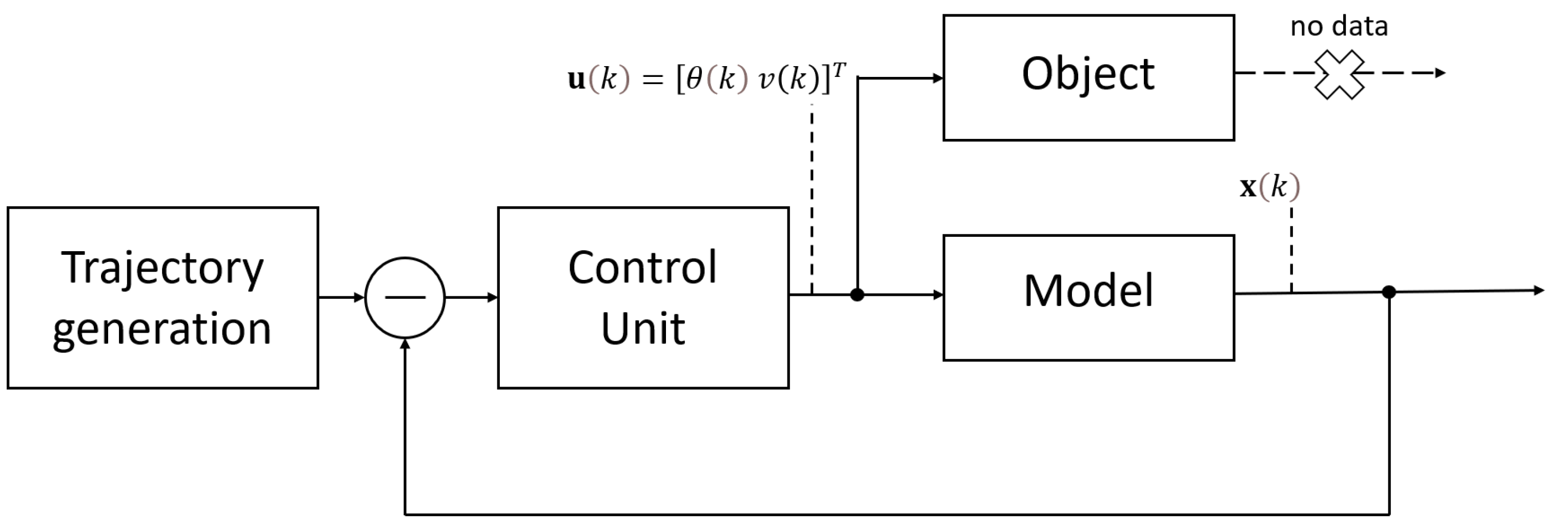
Depending on the task, the desired trajectory is set as a sequence of points on a plane or in three-dimensional space, and instead of calculating the distance to the trajectory, the distance to the points of the desired trajectory is determined. The block diagram of the unmanned vehicle control system, in which either PID-controller or model predictive control is used, is shown in Figure 4.

4. Controllers

4.1. Closed-Loop Control

In the steering control loop of the vehicle a P-controller was used. The control signal had the following form
α = arctan L ω v ,
where L is the distance between the axes of the robot, v and ω is the linear and angular velocities of the robot,
ω = v k ( s ) cos ( θ e ) 1 k ( s ) e k θ v θ e k e v sin ( θ e ) θ e e ,
where k ( s ) is a path curvature, θ e is an error in motion direction, e is a position error, and k θ and k e are controller coefficients.
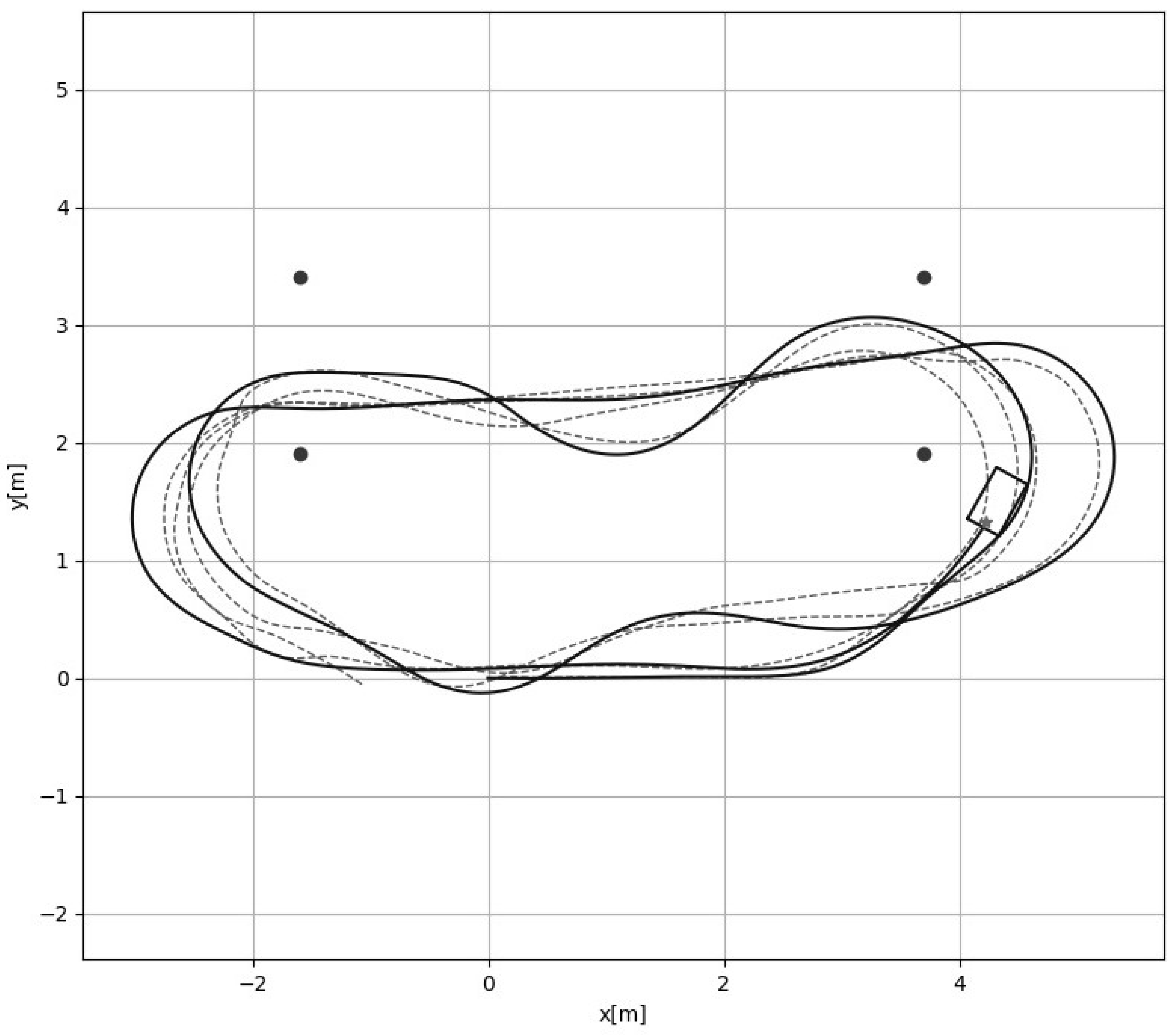
Figure 5 shows the results of tracking the desired trajectory using P-controller and an internal model. The dashed line shows the desired trajectory, and the solid line shows the trajectory that has been tracked. The dots mark the constraints in the form of gates.

4.2. Model Prediction Control

Predictive control is an optimization strategy that has a variety of advantages, such as accounting constraints imposed on system’s state and control signals, and ability to work with non-linear objects. The optimal trajectory is the solution to the optimization problem. Predictive control includes object simulation under various control actions that ensure current problem solution, for example, bypassing the obstacles or passing through a gate. Among the resulting set of trajectories, one trajectory is selected according to some criterion. As a criterion, the squared error of achieving the goal and the squared control signal with some weighting factors are often used
J = i = 1 L w x ( r i x i ) 2 + i = 1 L w u Δ u i 2 ,
where w x and w u are weights, r i is a desired trajectory, x i is a manipulated variable, u i is a control signal, L is a control horizon.
The goal of predictive control lies in sequential search for optimal control strategy for a certain time interval that is called control horizon. Each time the first step of the strategy found is the only one applied. This step completed, the prediction horizon is being shifted and new optimization starts.
Online optimization taking place at every step has became possible due to the availability of high-performance computing facilities embedded on the vehicle’s board.
For the control object model (1) and the prediction horizon value equal to 8, the desired and obtained trajectories are shown in Figure 6.

5. Results

To study the approaches proposed, an environment for unmanned vehicles simulation based on ROS1 and ROS2 operating systems, has been developed.
Experimental comparison of control methods that apply internal model for real-time control was conducted, with the problem of unmanned vehicle trajectory tracking served as experimental domain. The control was carried out on the basis of P-controller and model predictive control (MPC). The results of field experiments are shown in Table 1. The difference between the length of the desired trajectory S 1 and the length of the path S 2 covered under different velocity v was used as a comparison criterion. The desired trajectory length was 67.4 m.
According to the experiments the following conclusions may be performed:
  • Control based on P-controller is distinguished by the possibility of using relatively simple controllers;
  • With both control methods being used at high vehicle speeds, the deviation from the trajectory increases significantly;
  • High speeds can be achieved if controller parameters are fine-tuned or in case of applying an intelligent P-controller that adapts to the speeds and curvature of the trajectory;
  • High-performance computers are needed for MPC.

Author Contributions

Conceptualization, I.P. and E.S.; methodology, I.P.; software, I.P.; validation, I.P. and V.M.; formal analysis, E.S.; investigation, I.P.; data curation, I.P.; writing—original draft preparation, I.P., E.S. and V.M.; writing—review and editing, E.S.; visualization, V.M.; supervision, I.P. All authors have read and agreed to the published version of the manuscript.

Funding

This research received no external funding.

Institutional Review Board Statement

Not applicable.

Informed Consent Statement

Not applicable.

Data Availability Statement

The experimental data for both methods is available at https://cloud.mail.ru/public/raik/h6vjgsMkR (accessed on 19 June 2023).

Conflicts of Interest

The authors declare no conflict of interest.

References

  1. Ljuing, L. System Identification; Prentice Hall PTR: Hoboken, NJ, USA, 1999. [Google Scholar]
  2. Pupkov, K.A.; Egupov, N.D.; Trofimov, A.I. Statisticheskie Metody Analiza, Sinteza i Identifikacii Nelinejnyh Sistem Avtomaticheskogo Upravleniya; BMSTU: Moscow, Russia, 1998. (In Russian) [Google Scholar]
  3. Liu, G.P. Nonlinear Identification and Control: A Neural Network Approach; Springer: Berlin/Heidelberg, Germany, 2012. [Google Scholar]
  4. Paden, B.; Cáp, M.; Yong, S.Z.; Yershov, D.; Frazzoli, E. A Survey of Motion Planning and Control Techniques for Self-driving Urban Vehicles. IEEE Trans. Intell. Veh. 2016, 1, 33–55. [Google Scholar] [CrossRef] [Green Version]
  5. Mehta, B.R.; Reddy, Y.J. Advanced process control systems. In Industrial Process Automation Systems; Mehta, B.R., Reddy, Y.J., Eds.; Butterworth-Heinemann: Oxford, UK, 2015; pp. 547–557. [Google Scholar] [CrossRef]
  6. Huang, B.; Kadali, R. Dynamic Modeling, Predictive Control and Performance Monitoring: A Data-Driven Subspace Approach; Springer: Berlin/Heidelberg, Germany, 2008; 241p. [Google Scholar]
  7. Kingma, D.P.; Ba, J. Adam: A Method for Stochastic Optimization. arXiv 2014, arXiv:1412.6980v8. [Google Scholar]
  8. Diveev, A.; Sofronova, E. The Synthesis of Optimal Control System by the Network Operator Method. In IFAC Proceedings Volumes; Elsevier: Amsterdam, The Netherlands, 2009; Volume 42, pp. 232–237. [Google Scholar]
Figure 1. Unmanned vehicle (a) and its kinematic movement control scheme (b).
Engproc 33 00038 g001
Figure 2. The trajectories of the vehicle movement on the plane { x , y } .
Engproc 33 00038 g002
Figure 3. The change of state and control components over time.
Engproc 33 00038 g003
Figure 4. Block diagram of an internal model control system.
Engproc 33 00038 g004
Figure 5. The movement along the trajectory with the help of internal model and P-controller.
Engproc 33 00038 g005
Figure 6. The movement along the trajectory with the help of internal model and model prediction control.
Engproc 33 00038 g006
Table 1. Results of field experiments.
Experiment NumberSpeed v, m/sDeviation When Using P-Controller S 1 , mDeviation When Using MPC S 2 , m
11.414.43.5
21.122.11.9
30.881.61.7
Disclaimer/Publisher’s Note: The statements, opinions and data contained in all publications are solely those of the individual author(s) and contributor(s) and not of MDPI and/or the editor(s). MDPI and/or the editor(s) disclaim responsibility for any injury to people or property resulting from any ideas, methods, instructions or products referred to in the content.