1. Introduction
Automatic carrier landing for UAVs is one of most critical challenging operations; the marine environment can introduce various disturbances to UAV control when landing on a carrier. Carrier motion, disturbance due to carrier airwake and atmospheric turbulence make it very hard to ensure a safe landing operation. A lot of studies have been conducted on this problem and some control schemes have been proposed accordingly [
1,
2,
3,
4]. In [
5], an MPC controller was designed for a linearized UAV system to handle the landing task with carrier heave motion. In [
6], an autoregressive model was used to predict the carrier motion and a preview control scheme was used to reject the disturbances. In [
7], an ADRC-based controller was designed for UAV control but only the pitch dynamics were considered. In this paper a detailed UAV model and disturbances model are introduced, and a control scheme with outer loop (navigation control) and inner loop (attitude control) is proposed based on the LADRC method to reject disturbances during the landing operation.
This paper is organized as follows: A typical fixed-wing UAV model and empirical models of atmospheric disturbances are introduced in
Section 2. In
Section 3, an ADRC double-loop control scheme is proposed and corresponding controllers are designed. Results of simulation experiments are illustrated in
Section 4. And some concluding remarks are given in
Section 5.
3. ADRC Control Scheme Design
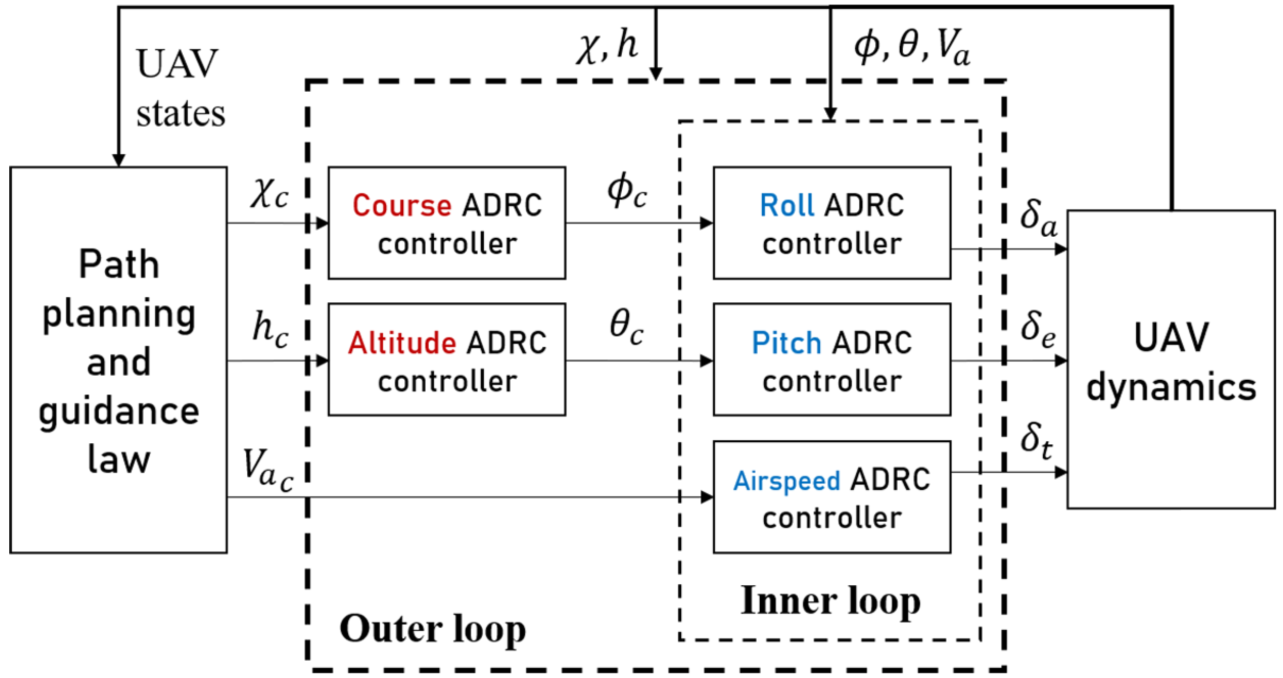
In this section, a cascade LADRC scheme is designed for UAV control during landing operation. As shown in
Figure 2, in the inner loop three single ADRC controllers are designed for attitude control and airspeed control. In the outer loop, navigation control is achieved through two ADRC controllers, which determine the desired attitude. The course, altitude and airspeed command are generated by path planning and a guidance algorithm; in this paper a simple guidance strategy and Dubins path are used; details can be found in [
8].
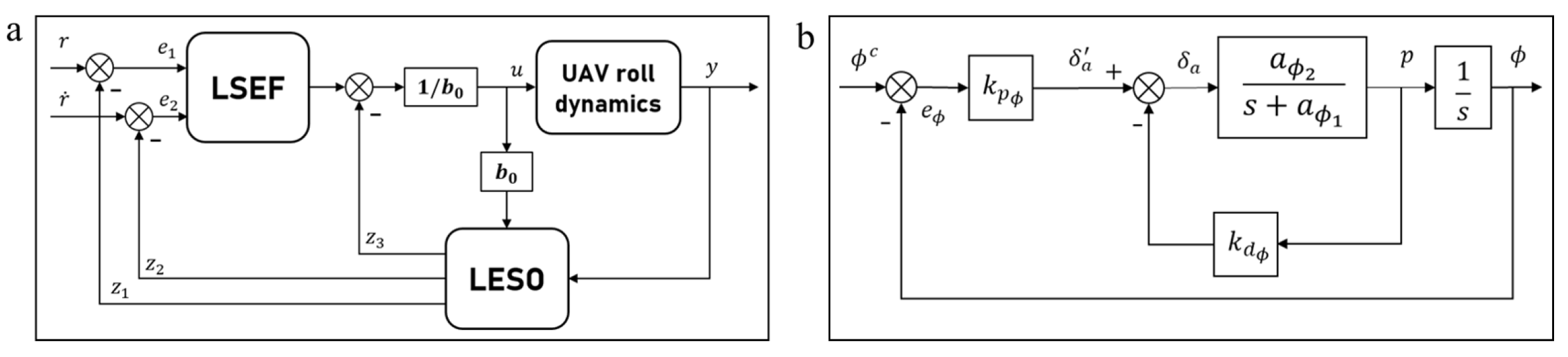
Similar to PID, the ADRC technique can be used only in SISO systems. In
Figure 3a the structure of a LADRC controller for roll control is shown. A typical LADRC controller consists of three parts: linear tracking differentiator (LTD), linear state error feedback control law (LSEF) and linear extended state observer (LESO). The LTD is used to generate a smooth transient profile; for simplicity it will not be discussed here; its definition can be found in [
8]. In practice, the LSEF is usually a PD controller; its parameter tuning will be discussed later in the end of this section. The LESO is the most important part of the ADRC controller; it estimates the “total disturbance” based on the input and output of the system. Consider an example of a second-order SISO system:
where
is an unknown external disturbance and
f is the total disturbance. The LESO for this system can then be constructed as a Luenberger observer. Treating total disturbance
f as an additional state
for system (
10), the corresponding LESO is then given by
where
y is the output measurement, which is state
;
is estimation of the total disturbance;
h is a derivative of
f; and
are the observer gains. In [
9], a tuning method for these coefficients in a second-order system was proposed:
,
is the LESO bandwidth.
The ADRC controllers for different state variables have to be designed individually, as shown in
Figure 3a. According to Equations (5)–(
9), both of the dynamics of roll and pitch can be simplified as SISO systems:
where
are the total disturbances to be estimated and
are control gains.
Since Equation (
9) is nonlinear in control input
, we must first linearize it to design the LESO for the airspeed dynamics. Let
be the deviation of
from trim, and
and
be the corresponding deviations. The new airspeed dynamics linearized around the trim condition are described as
where
is the disturbance; all the parameter definitions can be found in [
8].
Analogously, we can determine a SISO system for airspeed dynamics:
Then, according to (
11) the LESOs for airspeed, pitch and roll systems are designed as follows:
Altitude dynamics (
1) can be simplified as follows and course dynamics in conditions of coordinated turn with zero wind are described in [
8].
Then, the LESOs for altitude and course dynamics are given by
To ensure adequate performance of LESOs, their bandwidths must be chosen properly. A large bandwidth allows fast tracking without overshooting but, at the same time, high bandwidth could make the system very sensitive to noise. In this paper, bandwidth choice is made based on the natural frequency of the observer system.
Figure 3b shows a PD control diagram of the roll angle; the natural frequency of this second-order system can be calculated as follows:
where
is the maximum elevator deflection and
is the maximum roll angle. All the coefficients in
Figure 3b can be found in [
8].
Analogously, natural frequency for pitch, airspeed, altitude and course dynamics can be determined. Then, LESO bandwidths can be chosen empirically as
. Since the total disturbance is estimated by LESO, the estimation then can be used to compensate control input to make the control system robust and adaptive. Thus, the LADRC control law is formed as
.
is the control law given by LSEF,
r is the reference signal,
are the LESO outputs,
are the LSEF control gains and
is the LSEF controller bandwidth, in practice it is usually chosen between 4 and 20 [
9].
4. Simulation Results
The ADRC control scheme proposed in
Section 2 is implemented in the Simulink environment; to verify its advantages over PID controllers in terms of robustness and insensitivity to disturbances, several experiments are conducted to simulate the UAV carrier landing operation with ADRC and PID, respectively. The longitudinal and lateral dynamics of UAVs are usually discussed separately; to validate the effectiveness of the proposed algorithm on both of the dynamics, two stages of landing are considered: the orbit following and the final approach. The orbit is a spiral route over the carrier; it allows the landing officers to prepare the flight deck and ensure a safe landing. In the experiment the orbit is a Dubins path connected by four waypoints, which are shown in
Table 1. The Dubins path algorithm can be found in [
8]. And, for simplicity, a 3.5-degree glide slope is used as the final approach route.
Figure 4 shows wind gust turbulence and airwake disturbance. To better demonstrate the disturbance rejection performance of ADRC, in the experiment the gust intensity is multiplied by 20.
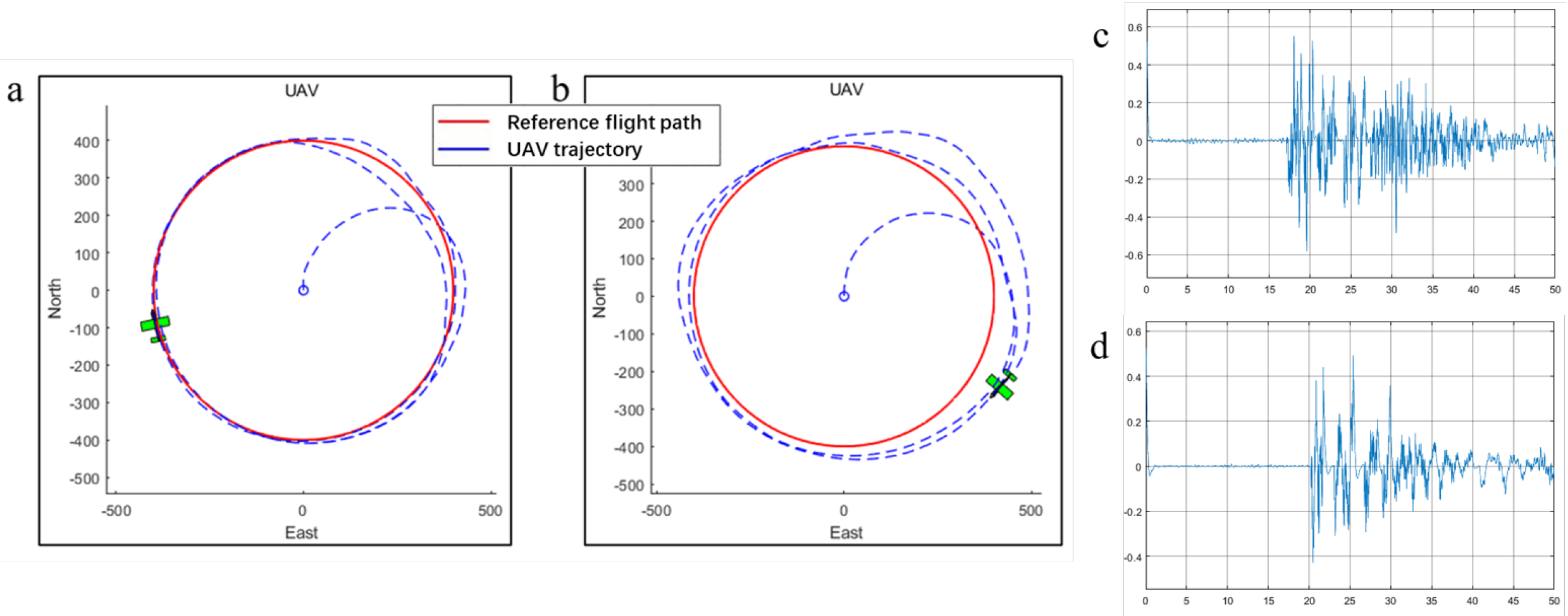
In the experiment a benchmark circle following maneuver that excites all the lateral states is used to illustrate lateral control performance. As shown in
Figure 5, even in the existence of intense wind gust ADRC can still follow the circle with high accuracy and from the tracking error result it can be seen that ADRC does suppress high-frequency noise.
Figure 6 shows that in terms of path following performance ADRC is far more effective and accurate than PID. The east position error of the ADRC algorithm at the end point is 11.5 m, which is almost two times less than the PID error, 19.4 m.
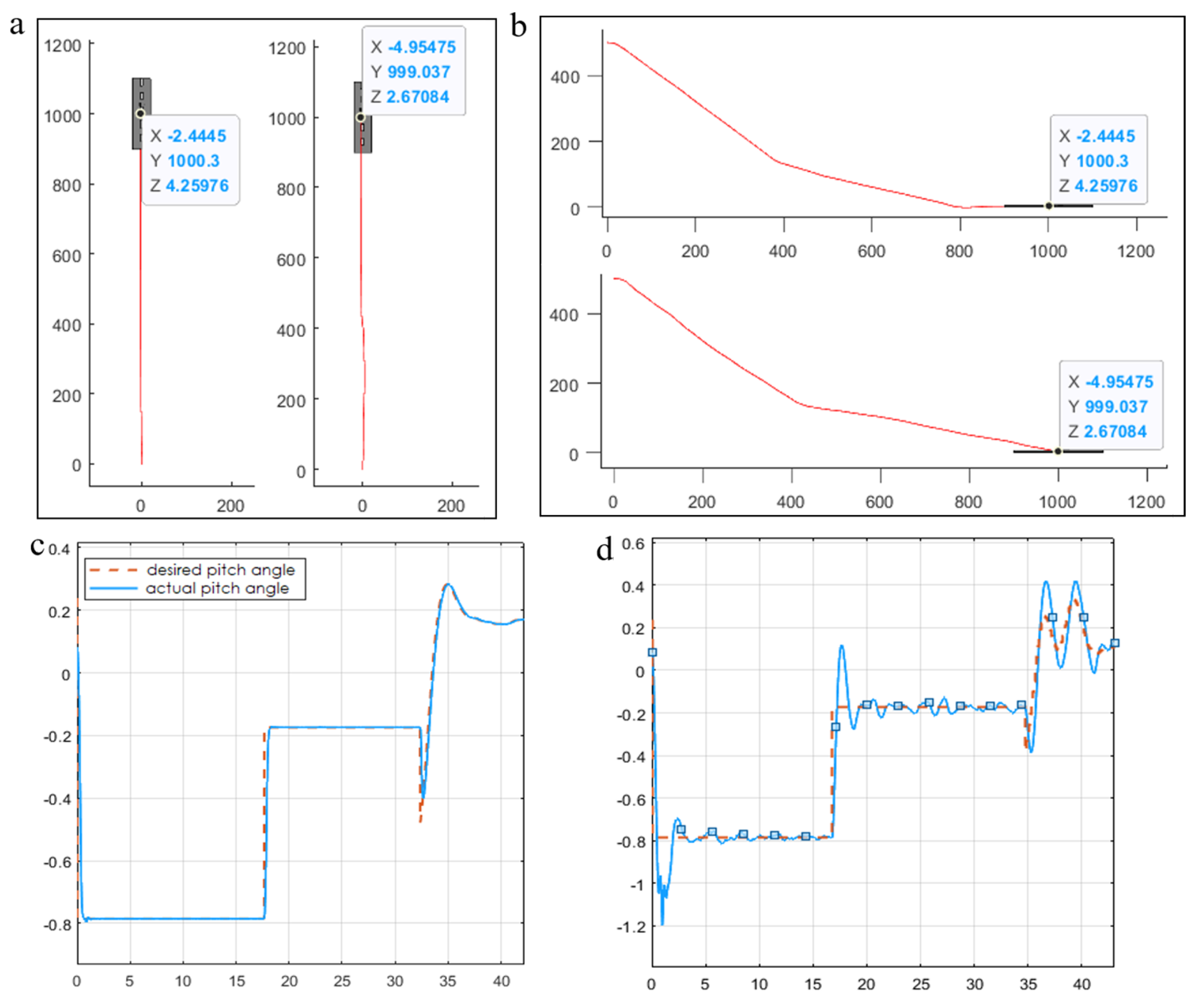
Figure 7 shows the results of final approach simulations. It can be seen that ADRC provides a smoother approach route than PID and the ADRC position error at touchdown point is 2.44 m, which is about half the PID error, 4.95 m. The initial conditions of UAV and carrier are shown in
Table 1.


