Abstract
In this paper the problem of atmospheric disturbances during the UAV carrier landing operation is considered. A UAV dynamics model, and a wind gust and airwake disturbance model are introduced. A LADRC-based cascade control scheme is developed for fixed-wing UAVs. In the control scheme, three ADRC controllers are designed for attitude control, and another two ADRC controllers are designed for course and altitude tracking. Finally, a series of simulations are implemented in Simulink and the results are presented to demonstrate the performance of the proposed control scheme.
1. Introduction
Automatic carrier landing for UAVs is one of most critical challenging operations; the marine environment can introduce various disturbances to UAV control when landing on a carrier. Carrier motion, disturbance due to carrier airwake and atmospheric turbulence make it very hard to ensure a safe landing operation. A lot of studies have been conducted on this problem and some control schemes have been proposed accordingly [1,2,3,4]. In [5], an MPC controller was designed for a linearized UAV system to handle the landing task with carrier heave motion. In [6], an autoregressive model was used to predict the carrier motion and a preview control scheme was used to reject the disturbances. In [7], an ADRC-based controller was designed for UAV control but only the pitch dynamics were considered. In this paper a detailed UAV model and disturbances model are introduced, and a control scheme with outer loop (navigation control) and inner loop (attitude control) is proposed based on the LADRC method to reject disturbances during the landing operation.
This paper is organized as follows: A typical fixed-wing UAV model and empirical models of atmospheric disturbances are introduced in Section 2. In Section 3, an ADRC double-loop control scheme is proposed and corresponding controllers are designed. Results of simulation experiments are illustrated in Section 4. And some concluding remarks are given in Section 5.
2. Mathematical Model
In this section we briefly describe UAV dynamics, then the considered fixed-wing UAV model is given, followed by a model of atmospheric disturbances.
2.1. Fixed-Wing UAV Model
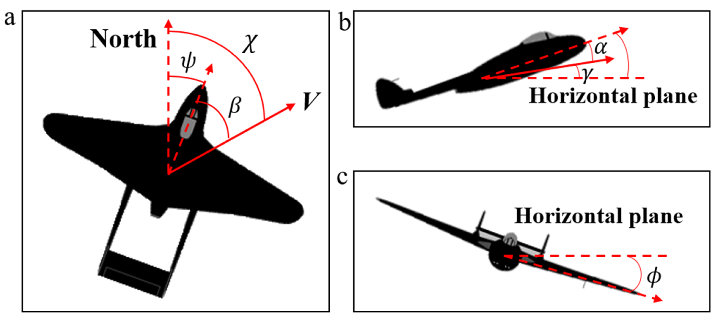
In the literature, various models are used to describe UAV dynamics, including the linear uncoupled model and the nonlinear cross-coupled model. This section presents a nonlinear 6-DOF UAV model with cross-couplings between yaw, roll and pitch motion. The body diagram of a fixed-wing UAV is shown in Figure 1. The 6-DOF UAV dynamics can be fully described using 12 states, i.e., . In this paper some states are ignored since guidance law design is beyond the scope of this paper (a Dubins path is used as a reference trajectory, see Section 3). Furthermore, we assume that the UAV is not equipped with a rudder and the yaw angle is controlled by the roll maneuver. The equations for describing the necessary controlled variables are given by (1)–(8).
where are roll axis, pitch axis and yaw axis components of airspeed in the UAV body frame, respectively; are roll and pitch angles, and their angular velocities; are control variables of throttle, aileron and elevator, respectively; are terms related to UAV aerodynamics; their definitions can be found in [8].
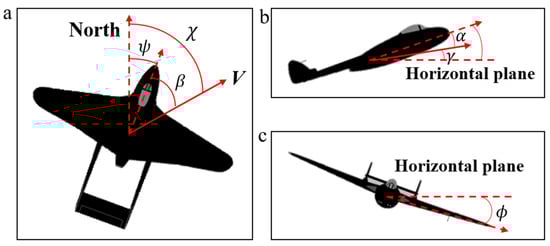
Figure 1.
UAV body diagram: (a) vertical view; (b) end view; (c) front view.
Airspeed is calculated using Equations (2)–(4):
where is the angle of attack and is a disturbance related to sideslip angle .
Then, Equations (2)–(4) can be replaced by (9) after some substitutions:
where are some coefficients and is a disturbance similar to . Their definitions are given in [8].
2.2. Disturbance Model
In this paper two primary disturbance sources are considered: atmospheric turbulence (wind gust) and carrier airwake. Throughout the whole flight, the UAV is under the influence of wind gust, while disturbance due to airwake only affects the landing process, i.e., when the UAV is close to the carrier. Experiments show that a reliable wind turbulence model should include a steady component and a random component (gust), which can be generated by filtering Gauss white noise with zero mean and unit variance:
where are the transfer functions; are the gust intensities on corresponding axes; and are the gust wavelengths [8]. Airwake starts to affect the UAV at about 800 m from the carrier; the resulting disturbance can be divided into four parts: free air turbulence component, steady component, periodic component and random component. The main factor is the steady component, which is usually described by empirical expressions [6]
where denotes the axial airwake disturbance; denotes the normal airwake disturbance; and t denotes time before touchdown.
3. ADRC Control Scheme Design
In this section, a cascade LADRC scheme is designed for UAV control during landing operation. As shown in Figure 2, in the inner loop three single ADRC controllers are designed for attitude control and airspeed control. In the outer loop, navigation control is achieved through two ADRC controllers, which determine the desired attitude. The course, altitude and airspeed command are generated by path planning and a guidance algorithm; in this paper a simple guidance strategy and Dubins path are used; details can be found in [8].
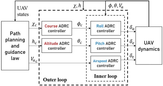
Figure 2.
Cascade ADRC control scheme for fixed-wing UAV.
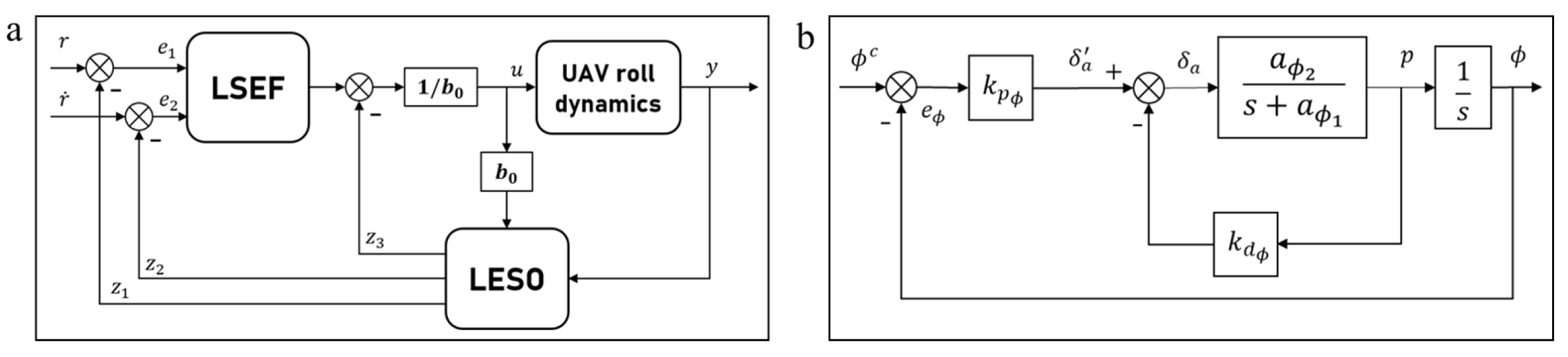
Similar to PID, the ADRC technique can be used only in SISO systems. In Figure 3a the structure of a LADRC controller for roll control is shown. A typical LADRC controller consists of three parts: linear tracking differentiator (LTD), linear state error feedback control law (LSEF) and linear extended state observer (LESO). The LTD is used to generate a smooth transient profile; for simplicity it will not be discussed here; its definition can be found in [8]. In practice, the LSEF is usually a PD controller; its parameter tuning will be discussed later in the end of this section. The LESO is the most important part of the ADRC controller; it estimates the “total disturbance” based on the input and output of the system. Consider an example of a second-order SISO system:
where is an unknown external disturbance and f is the total disturbance. The LESO for this system can then be constructed as a Luenberger observer. Treating total disturbance f as an additional state for system (10), the corresponding LESO is then given by
where y is the output measurement, which is state ; is estimation of the total disturbance; h is a derivative of f; and are the observer gains. In [9], a tuning method for these coefficients in a second-order system was proposed: , is the LESO bandwidth.
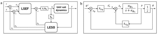
Figure 3.
(a) ADRC controller structure; (b) roll angle control diagram.
The ADRC controllers for different state variables have to be designed individually, as shown in Figure 3a. According to Equations (5)–(9), both of the dynamics of roll and pitch can be simplified as SISO systems:
where are the total disturbances to be estimated and are control gains.
Since Equation (9) is nonlinear in control input , we must first linearize it to design the LESO for the airspeed dynamics. Let be the deviation of from trim, and and be the corresponding deviations. The new airspeed dynamics linearized around the trim condition are described as
where is the disturbance; all the parameter definitions can be found in [8].
Analogously, we can determine a SISO system for airspeed dynamics:
Then, according to (11) the LESOs for airspeed, pitch and roll systems are designed as follows:
Altitude dynamics (1) can be simplified as follows and course dynamics in conditions of coordinated turn with zero wind are described in [8].
Then, the LESOs for altitude and course dynamics are given by
To ensure adequate performance of LESOs, their bandwidths must be chosen properly. A large bandwidth allows fast tracking without overshooting but, at the same time, high bandwidth could make the system very sensitive to noise. In this paper, bandwidth choice is made based on the natural frequency of the observer system.
Figure 3b shows a PD control diagram of the roll angle; the natural frequency of this second-order system can be calculated as follows:
where is the maximum elevator deflection and is the maximum roll angle. All the coefficients in Figure 3b can be found in [8].
Analogously, natural frequency for pitch, airspeed, altitude and course dynamics can be determined. Then, LESO bandwidths can be chosen empirically as . Since the total disturbance is estimated by LESO, the estimation then can be used to compensate control input to make the control system robust and adaptive. Thus, the LADRC control law is formed as . is the control law given by LSEF, r is the reference signal, are the LESO outputs, are the LSEF control gains and is the LSEF controller bandwidth, in practice it is usually chosen between 4 and 20 [9].
4. Simulation Results
The ADRC control scheme proposed in Section 2 is implemented in the Simulink environment; to verify its advantages over PID controllers in terms of robustness and insensitivity to disturbances, several experiments are conducted to simulate the UAV carrier landing operation with ADRC and PID, respectively. The longitudinal and lateral dynamics of UAVs are usually discussed separately; to validate the effectiveness of the proposed algorithm on both of the dynamics, two stages of landing are considered: the orbit following and the final approach. The orbit is a spiral route over the carrier; it allows the landing officers to prepare the flight deck and ensure a safe landing. In the experiment the orbit is a Dubins path connected by four waypoints, which are shown in Table 1. The Dubins path algorithm can be found in [8]. And, for simplicity, a 3.5-degree glide slope is used as the final approach route.

Table 1.
Initial conditions of final approach simulation.
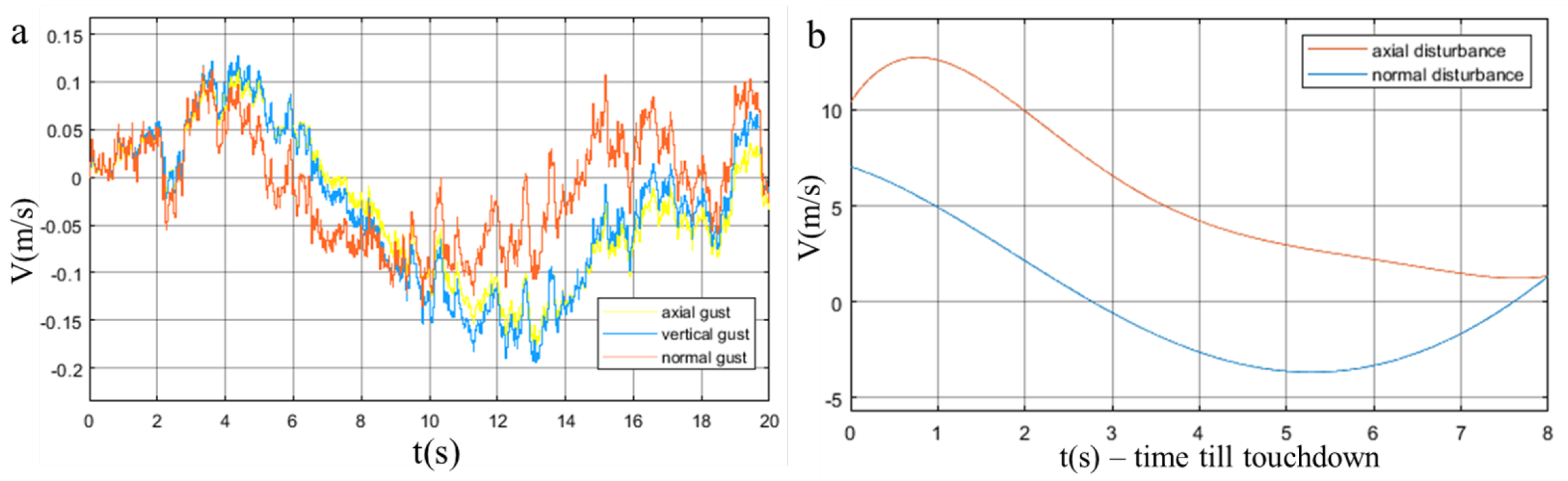
Figure 4 shows wind gust turbulence and airwake disturbance. To better demonstrate the disturbance rejection performance of ADRC, in the experiment the gust intensity is multiplied by 20.

Figure 4.
(a) Gust velocity in UAV body frame; (b) airwake disturbance velocity.
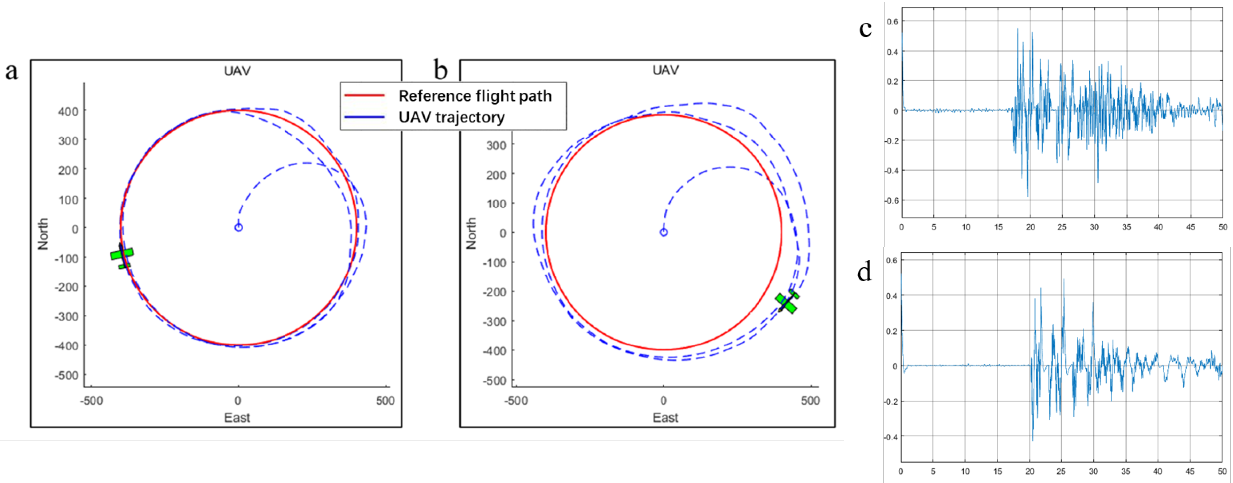
In the experiment a benchmark circle following maneuver that excites all the lateral states is used to illustrate lateral control performance. As shown in Figure 5, even in the existence of intense wind gust ADRC can still follow the circle with high accuracy and from the tracking error result it can be seen that ADRC does suppress high-frequency noise.
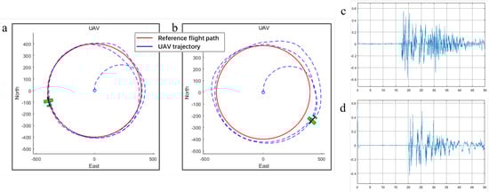
Figure 5.
(a) Circle following with ADRC; (b) circle following with PID; (c) PID roll tracking error; (d) ADRC roll tracking error.
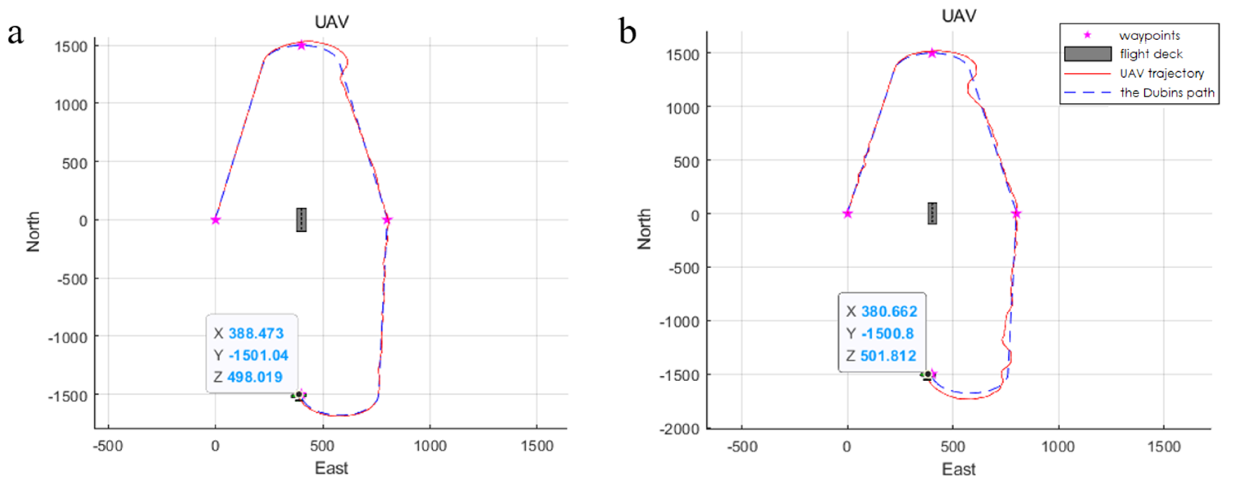
Figure 6 shows that in terms of path following performance ADRC is far more effective and accurate than PID. The east position error of the ADRC algorithm at the end point is 11.5 m, which is almost two times less than the PID error, 19.4 m.
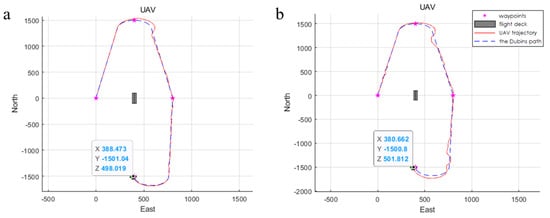
Figure 6.
(a) ADRC orbit following result; (b) PID orbit following result.
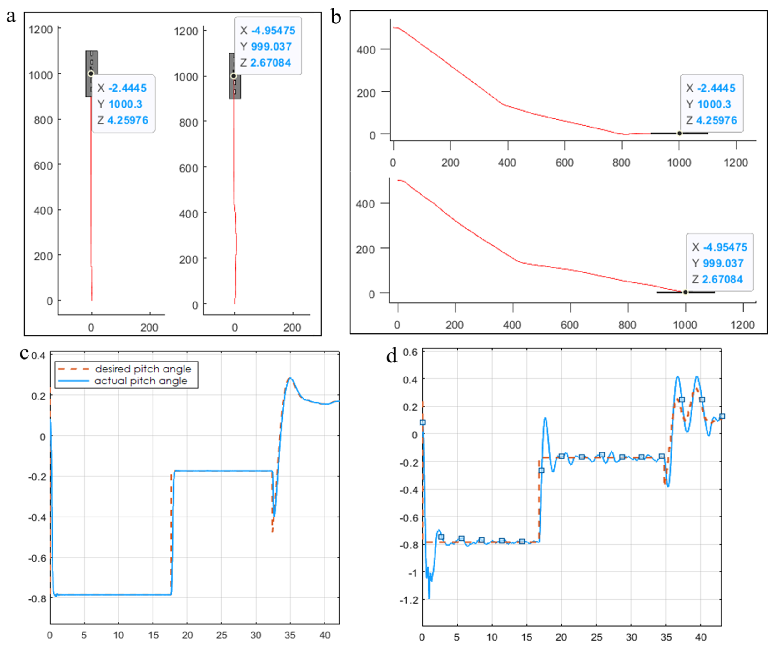
Figure 7 shows the results of final approach simulations. It can be seen that ADRC provides a smoother approach route than PID and the ADRC position error at touchdown point is 2.44 m, which is about half the PID error, 4.95 m. The initial conditions of UAV and carrier are shown in Table 1.

Figure 7.
(a) Vertical view of final approach results (left: ADRC, right: PID); (b) end view of final approach results; (c) ADRC pitch tracking result; (d) PID pitch tracking result.
5. Conclusions and Future Work
This paper described our work on the topic of automatic UVA carrier landing. In this work a cascade ADRC control scheme was proposed for fixed-wing UAVs. The influence of wind gust and atmospheric disturbance due to carrier airwake was studied. In addition, a UAV dynamics simulation system was developed in the Simulink environment and the proposed control scheme was tested by a series of simulations. The results verified the effectiveness of the ADRC control scheme compared to the PID control:
- The controller design and parameter tuning processes for ADRC are much easier than for PID;
- The ADRC control system has excellent robustness and accuracy even in the presence of intense disturbances.
As further work on this project, we will try to exploit the total disturbance information more comprehensively; an adaptive navigation method based on the LESO will be studied as an extension of the UAV control system proposed in this paper.
Author Contributions
Conceptualization, R.Z.; methodology, K.A.N. and R.Z.; software, R.Z.; validation, R.Z.; formal analysis, K.A.N.; writing—original draft preparation, R.Z.; writing—review and editing, K.A.N.; visualization, R.Z.; supervision, K.A.N. All authors have read and agreed to the published version of the manuscript.
Funding
This research received no external funding.
Institutional Review Board Statement
Not applicable.
Informed Consent Statement
Not applicable.
Data Availability Statement
No new data were created or analyzed in this study. Data sharing is not applicable to this article.
Conflicts of Interest
The authors declare no conflict of interest.
Abbreviations
The following abbreviations are used in this manuscript:
| ADRC | Active disturbance rejection control |
| LADRC | Linear active disturbance rejection control |
| LTD | Linear tracking differentiator |
| LSEF | Linear state error feedback control law |
| LESO | Linear extended state observer |
References
- Hess, R.A. Analysis of the Aircraft Carrier Landing Task, Pilot + Augmentation/Automation. In 2019 IFAC-PapersOnLine; Elsevier: Amsterdam, The Netherlands, 2019; pp. 359–365. [Google Scholar]
- Zhang, L.; Wang, S.; Selezneva, M.S.; Neusypin, K.A. A new adaptive Kalman filter for navigation systems of carrier-based aircraft. Chin. J. Aeronaut. 2022, 35, 416–425. [Google Scholar] [CrossRef]
- Zhang, L. Flight Control Quality Assessment of Carrier-Based Aircraft Using Degree of Controllability Criterion. Aerosp. Instrum. 2021, 12, 10–18. [Google Scholar]
- Shen, K.; Zhang, L.; Selezneva, M.S.; Neusypin, K.A. Modification of federated Kalman filter in the correction scheme of aircraft carrier navigation systems. Autom. Mod. Technol. 2020, 73, 177–180. [Google Scholar]
- Zhou, R.; Neusypin, K.A. Model predictive control for automatic carrier landing considering ship motion. J. Phys. Conf. Ser. 2022, 2235, 012005. [Google Scholar] [CrossRef]
- Zhen, Z.; Miao, P.; Xue, Y.; Jiang, S. Robust preview control and autoregressive prediction for aircraft automatic carrier landing. IEEE Access 2019, 7, 18273–18283. [Google Scholar] [CrossRef]
- Yu, Y.; Wang, H.; Shao, X.; Huang, Y. The attitude control of UAV in carrier landing based on ADRC. In Proceedings of the 2016 IEEE Chinese Guidance, Navigation and Control Conference (CGNCC), Nanjing, China, 12–14 August 2016; pp. 832–837. [Google Scholar]
- Randal, W.B.; Timothy, W.M. Small Unmanned Aircraft: Theory and Practice; Princeton University Press: Princeton, NI, USA, 2012. [Google Scholar]
- Gao, Z. Scaling and Bandwidth-Parameterization Based Controller Tuning. In Proceedings of the 2003 American Control Conference, Denver, CO, USA, 4–6 June 2003; pp. 4989–4996. [Google Scholar]

Disclaimer/Publisher’s Note: The statements, opinions and data contained in all publications are solely those of the individual author(s) and contributor(s) and not of MDPI and/or the editor(s). MDPI and/or the editor(s) disclaim responsibility for any injury to people or property resulting from any ideas, methods, instructions or products referred to in the content. |
© 2023 by the authors. Licensee MDPI, Basel, Switzerland. This article is an open access article distributed under the terms and conditions of the Creative Commons Attribution (CC BY) license (https://creativecommons.org/licenses/by/4.0/).