1. Introduction
IPMSM motors are becoming increasingly widespread in commercial motor drive systems as vector control (VC) technology advancements. In order to regulate the speed using this technique, a speed sensor, namely a shaft encoder, is essential. Nevertheless, a speed sensor is impractical in certain situations, such as hostile environment electric motors and high-speed motor drives. Additionally, cautious cabling configurations taking electrical noise into account are required. Furthermore, it substantially increases the system cost and motor size. Recently, a number of motion-Sensorless VC schemes [
1,
2] have been advocated.
The stator flux (SF) is approximated via integrating a back EMF for sensorless speed vector control. With regard to initial state and dc offset, simple integrator back EMF integration suffers from drift and saturation. The most frequent solution is to use a low pass filter (LPAF) in place of the simple integrator. To solve the problem, a LPAF should supplant the simple integrator [
3]. Several efforts have been developed to resolve the issue [
4,
5]. A digital filter was offered as a solution to the problem of drift [
3]. A simple integrator is used to estimate the amplitude of the SF in this method.
Alternatively, both the coordinate angle and speed are computed employing a computational filter with a pole further beyond the origin. Due to drift and saturation, the magnitude of the SF vector is inaccurately estimated by a purely integrator. Moreover, whenever the operational frequency of the electric motor is below the threshold frequency of the computational filter, a deviation will be generated in a measurement of the synchronous angle. To address the drift difficulty and precisely compute stator flux [
4,
5], a cascaded programmable LPAF was proposed. However, if the RPM of the motor is almost 0, the time constant of the LPAF will be significant.
A great number back EMF observers have already been developed and used in commercial applications over the past several decades. However, the back EMF signal degrades at slower motor speeds, rendering these techniques ineffective at low speeds [
6]. However, this problem is easily avoided when using the flux observer, which is simply the integration of back EMF signals, since the intensity of this flux linkage is independent of speed. Nevertheless, a simple integrator experiences drift because actuators constantly consist of a DC offset. A new integration approach was proposed in refs. [
7,
8] that utilizes the employ of the orthogonality within the back EMF alongside the flux to compensate for the flux angle over a broad speed domain. Nevertheless, the presence of a back EMF signal introduces disturbance into the entire system and degrades its performance. In recent years, the PMSM speed control system has utilized a nonlinear algorithm known as ADRC [
9]. State observers (SO), along with disturbance observers (DOB), have been employed to mitigate the adverse impacts of external disturbances [
9,
10,
11,
12]. These observers have been designated as the most effective method for estimating model uncertainty and external disturbances (ED). The SO can be expanded to estimate the ED, in addition to internal disturbances, including the Uncertain Parameters. ADRC, a replacement technique for the traditional PI controller used in the industry, integrates with the “extended state observer” (ESO) [
9].
This article analyzes the issues related to slow-speed flux estimations as a Voltage Model observer is utilized. Since pure integration cannot be performed due to noise in the measured signals, low-pass filters must be commonly employed in place of integrators. At low velocities, flux estimates are imprecise regarding both amplitude and angle; consequently, the position of the rotor calculated employing the Direct Field Orientation method is incorrect. This work focuses on developing an effective flux observer for vector-controlled AC devices with sinusoidal shape flux distributions. This technique relies on an enhanced integrator with a voltage model: the DC-drift ADRC-correcting loop. The correction error uses the size of the standard flux to restrict the path of the flux vector into a circle. By employing a PLL with an ADRC state estimator, the SF vector is utilized to derive speed and position.
2. Conventional Flux Observer Analysis
The SF in the
stationary reference frame is computed as
where
are stator voltage and stator current, and
is stator resistance. Integrating (1) with a simple integrator provides sensitive drift and saturation issues. The pure integrator is substituted with an LPAF to address the problems. The estimated SF by the LPAF can be expressed as
where
is the estimated SF by LPAF,
is a back-EMF and
is a pole of the system. The error becomes more significant whenever the motor’s frequency becomes lower than the LPAF threshold frequency. To eliminate the issue, the LPAF in (2) must have a very low threshold frequency. However, the drift phenomenon still exists since the LPAF have a very large time constant. From Equations (1) and (3), the transfer function from the actual value flux linkage
to the projected one based on LPAF
can be defined as follows:
where
represents the threshold frequency. The frequency transfer function of Equation (3) is provided by:
The stator flux linkage’s angular velocity is determined as
where
is the orientation of
.
In the state of equilibrium, and the rotor’s angular trajectory are identical. The computation error for the stator flux linkage can be determined by (5) since (3) has been utilized to the estimator. Therefore, the accuracy of estimation is dependent on angular velocity.
3. Design of Novel Observer
In order to accomplish a more accurate rotor position, an enhanced flux observer is introduced in this section. The proposed flux observer includes a back EMF observer, a simple integrator, a current flux observer, and an ADRC offset eliminator. The scheme for eliminating drift is depicted in
Figure 1.
Synchronous rotating coordinates are employed to estimate the stator flux linkage.
Stator flux linkage values
and
are computed in the two-phase static coordinate framework after 2r/2s transformation. Due to an error in measurement and the accumulative impact caused by integration, the estimated integral trajectory of back EMF might deviate substantially compared with the actual flux linkage of the IPMSM. The mathematical technique’s concept underlying this phenomenon is the fact that the estimation errors of back EMF is primarily derived from two possible causes: the high order frequency burrs triggered by electrical noise, while the lower frequencies or DC error is initiated by the unreliable nil position of the voltage, and the currents data acquisition module. ADRC is a model-free control algorithm employed in the design of controllers for systems with indeterminate dynamics and external disturbances [
9]. The technique necessitates only an approximation of the plant’s dynamics in order to design controllers with robust disturbance rejection and no overshoot. ADRC has demonstrated superior control performance compared to PID. The majority of reported applications of ADRC involve motion control. The variation within an observed flux and the projected reference flux is the primary component of the compensation element employed to the ADRC compensation in order to suppress the integral drift. The flux estimator operates as an integrator with no delay and a high degree of dynamics. The integrated ADRC controllers have the ability to quickly and precisely adapt for external disturbances as depicted in
Figure 2.
4. Simulation Results
Figure 3 depicts a fundamental structure of the block diagram of the ADRC-based sensorless PMSM system with DC-offset elimination loops. This system is controlled by the
mechanism. The PMSM control mechanism simulation model was developed in MATLAB/Simulink; motor parameters are listed in
Table 1.
Low Speed
Figure 4 shows the IPMSM actual and estimated speed, flux, and the angle estimation and estimation error waveforms by the traditional flux observer; when an interior PMSM works at 300 rpm, a 0.11 V DC offset under the
-axis is applied at 1.5 s at the no-load condition. It is evident that traditional flux observers will produce inaccurate estimates of the rotor’s flux, velocity, and position when the model adds a DC-offset component. The flux and also speed estimation are inaccurate because the simple integral pole is located in the origin.
Figure 5 illustrates the dynamic features of the ADRC controller in relation to the DC offset error part. The back EMF keeps the sharp pulsing throughout the time a 0.7 V DC drift error is enforced to the line-to-line back EMF at 0 s. The proposed technique immediately initiated DC-offset error mitigation in actual time.
Using a modified and enhanced ADRC compensator suppresses DC-drift influence in less than 1 s, reducing the time needed to reach stability and show substantial interference suppression. The amplitude of the DC-drift error value is increased from 0.7–0.1 V, 1–1.5 V, and 1.5–2 V at 2.1, 3.9, and 5.6 s, respectively. Within less than half a second, the ADRC compensator eliminates the effect of DC bias. The flux linkage oscillation is effectively reduced through the DC-drift compensator and ADRC controller, and its constant value is maintained. Compensation is carried out regardless of whether the DC-bias error component is present. Although the DC-drift error element changes in amplitude, the compensating functions are verified to be effective in real time. It is evident from the simulation findings that the ADRC control technique provides superior steady-state performance as well as outstanding dynamical performance.
The proposed ADRC compensator waveforms for flux and speed are shown in
Figure 6 and
Figure 7, respectively. The results demonstrate that the estimated fluxes are extremely closer to the actual fluxes. When the DC-drift error value is increased, both the speed and the flux estimation remain stable in a steady state. In the steady state, the transient estimation of speed has minimal ripple and high precision.


 and
and 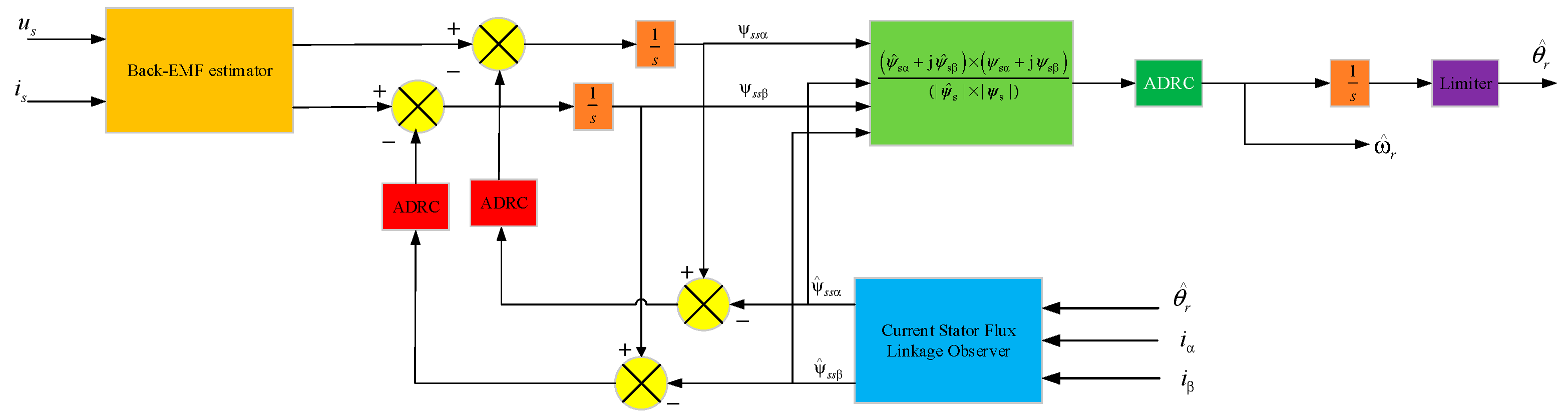


