Proceeding Paper

Study on Building Information Modeling Application for Building Space Design Conflict Effects †

Department of Internal Design and Civil Engineering, Vanung University, Taoyuan 320313, Taiwan
Presented at the IEEE 5th Eurasia Conference on Biomedical Engineering, Healthcare and Sustainability, Tainan, Taiwan, 2–4 June 2023.
Eng. Proc. 2023, 55(1), 93; https://doi.org/10.3390/engproc2023055093
Published: 18 January 2024

Abstract

:
In building structure design, refinements during construction for practical use or space conflicts induce construction delays and budget increases. Building information modeling (BIM) provides a 3D building model which includes the structure’s size, material, and construction information so designers clearly understand the whole construction process. For an irregular shaped building or elements such as a ramp or a curved roof, space conflict problems occur. The Autodesk’s Navisworks program provides a visual analysis tool for users to roam in a 3D model to simulate possible space conflicts and avoid them before the final design. In this study, we used the AutoDesk Revit program to set up a building system with a Navisworks space distance measurement tool to confirm the design’s rationality. An optimal structure system design process is proposed for practical applications to reduce the possibility of design changes.

1. Introduction

For building systems, the establishment of a spatial structure system needs to consider the user’s requirements so that a discontinuous design structure system or insufficient space and height can be avoided. Changes in design will delay construction time and impact the budget. Scholars have discussed the issue. Fazil et al. [1] used BIM combined with Navisworks to set up a construction management (CM) system. Latiffi et al. [2] discussed the application of BIM in the Malaysian industry system and its benefit. Xu et al. [3] integrated Revit and Tekla into Navisworks to set up a steel structure building system and compared the difference. In real building structure design, engineers define the element sizes to confirm the building’s safety and ensure its use function fits the space need. Thus, we combine BIM and Navisworks programs to develop a useful design process for structural designers to reduce design change problems.

2. BIM for Irregular Structure System Design and Spatial Impact Analysis

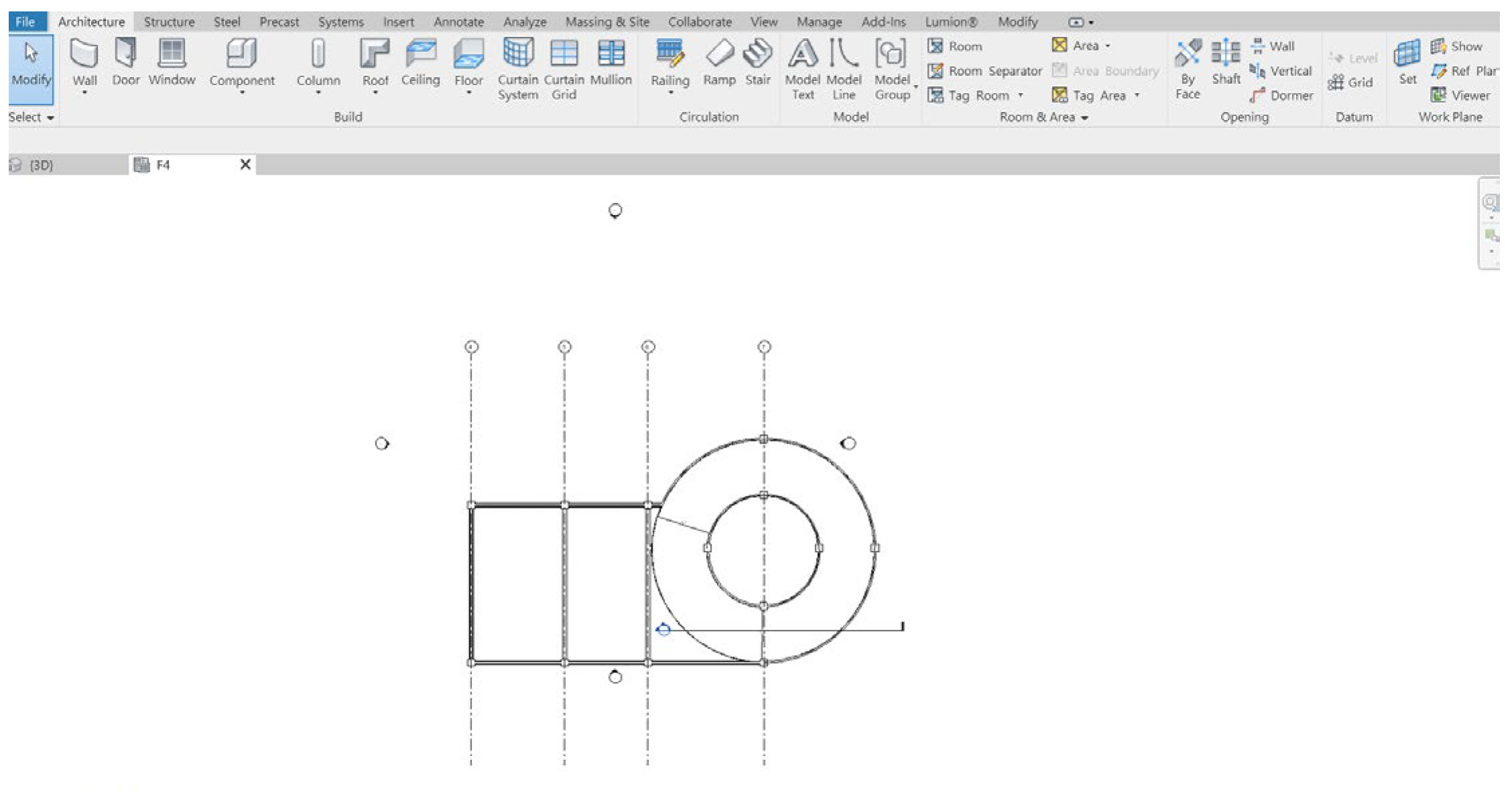
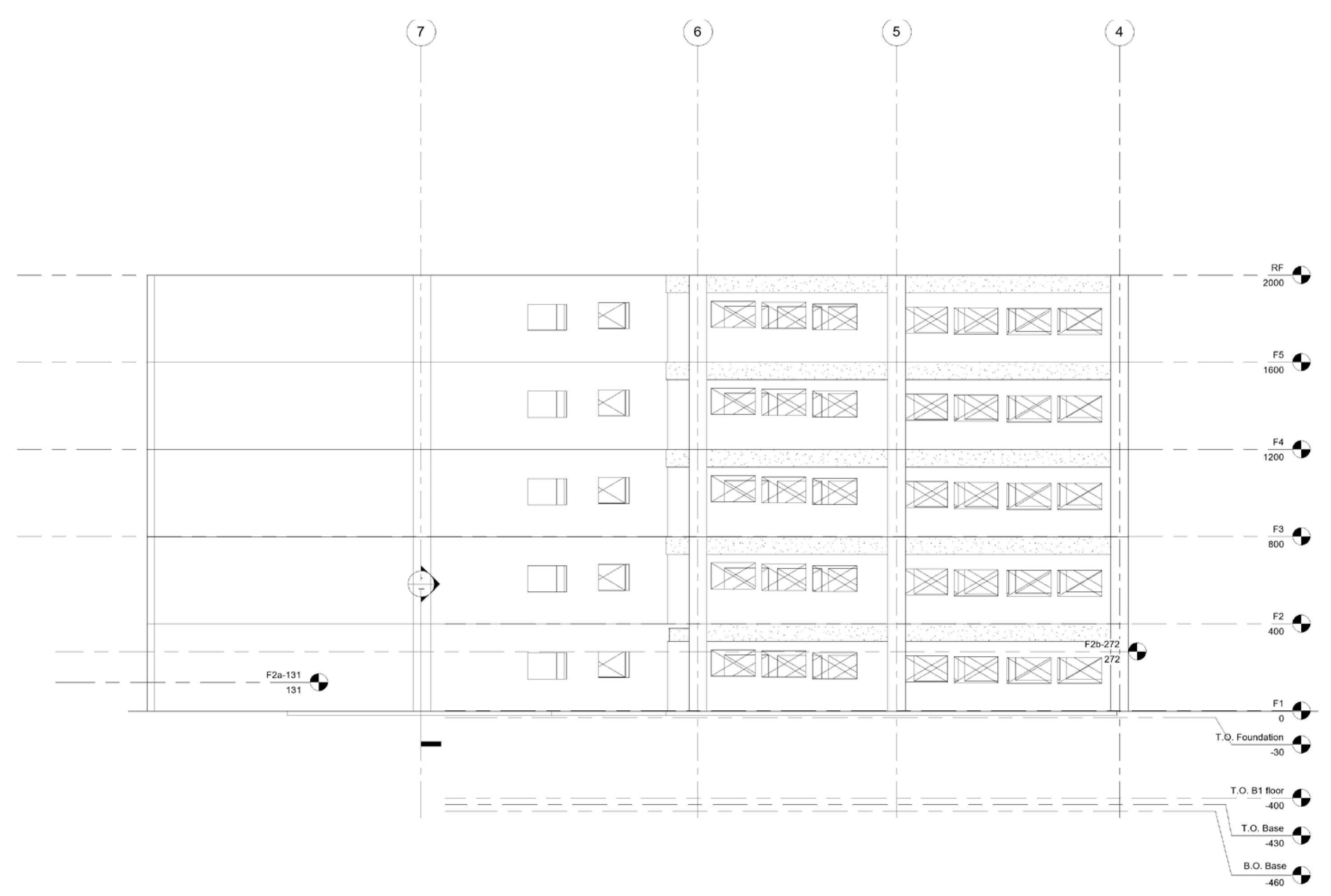
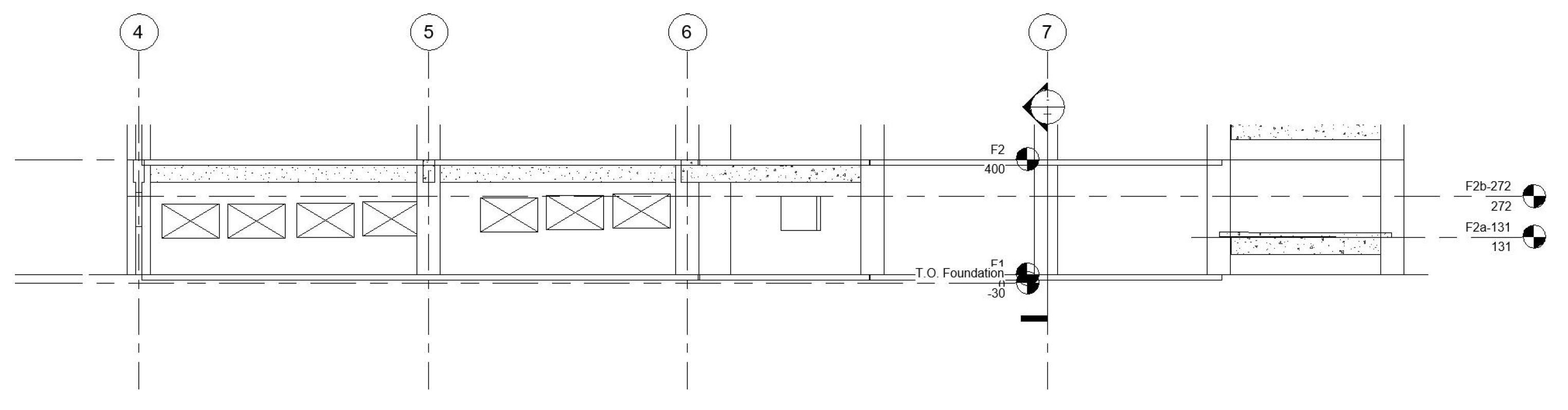
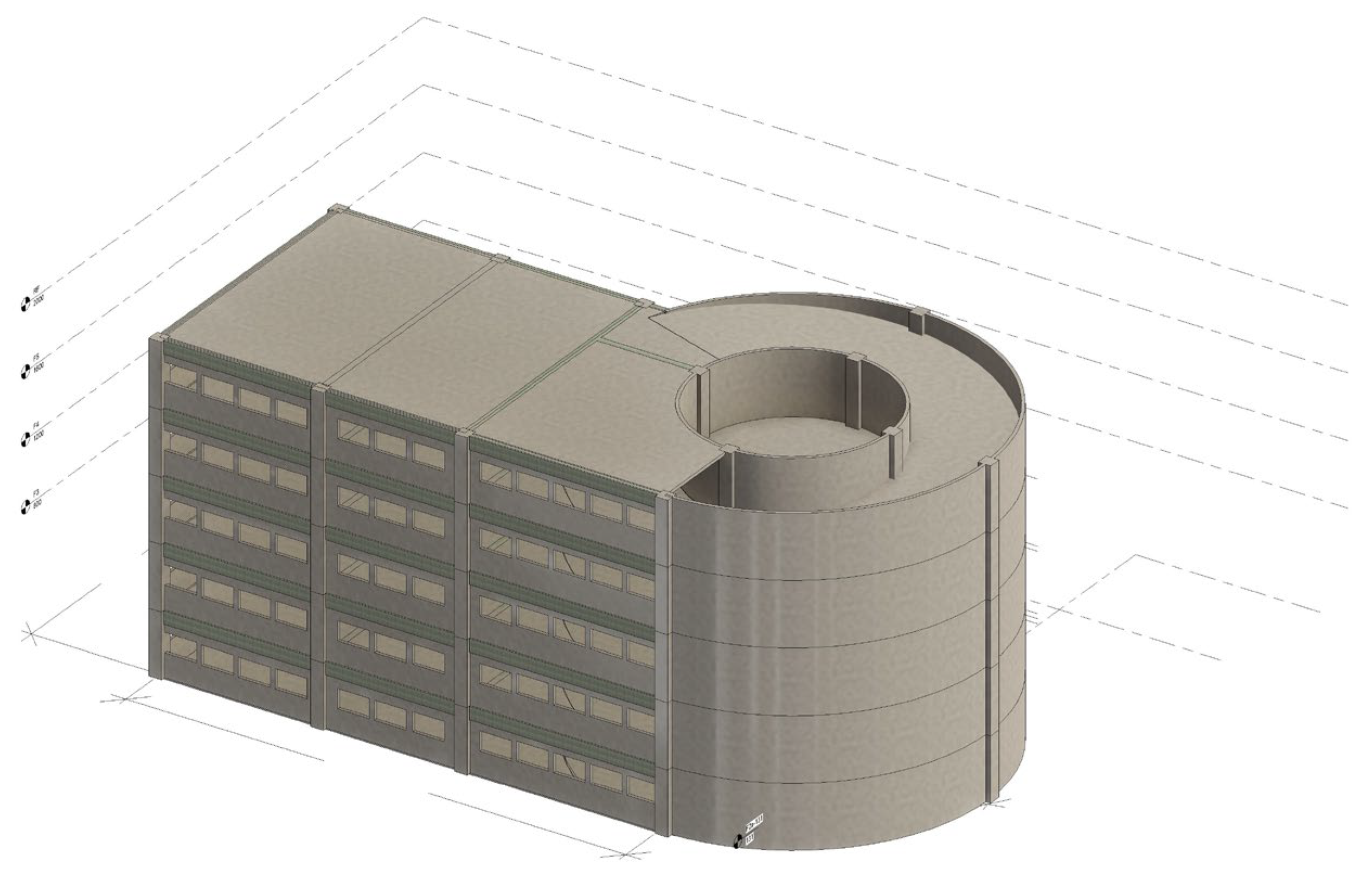
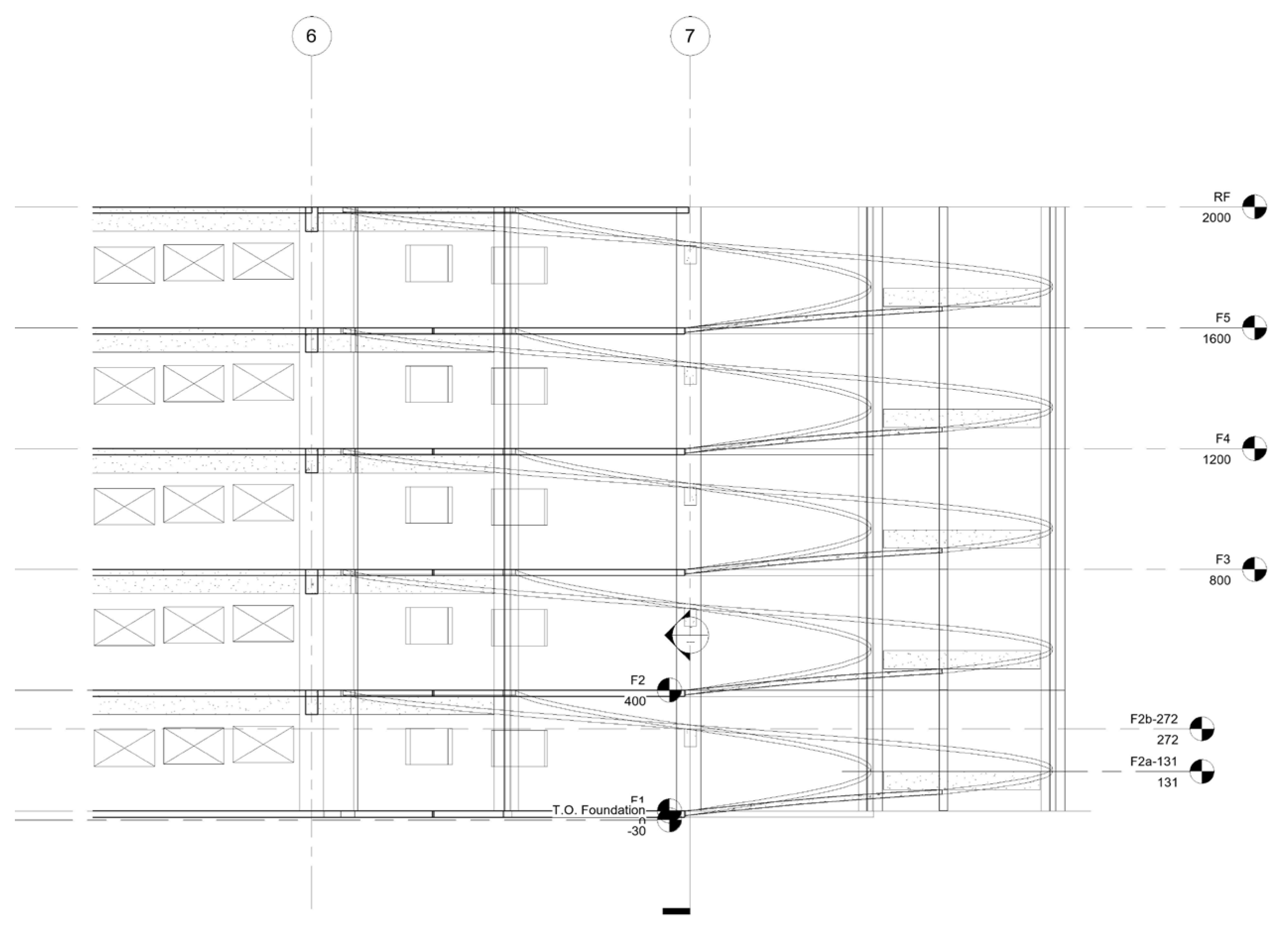
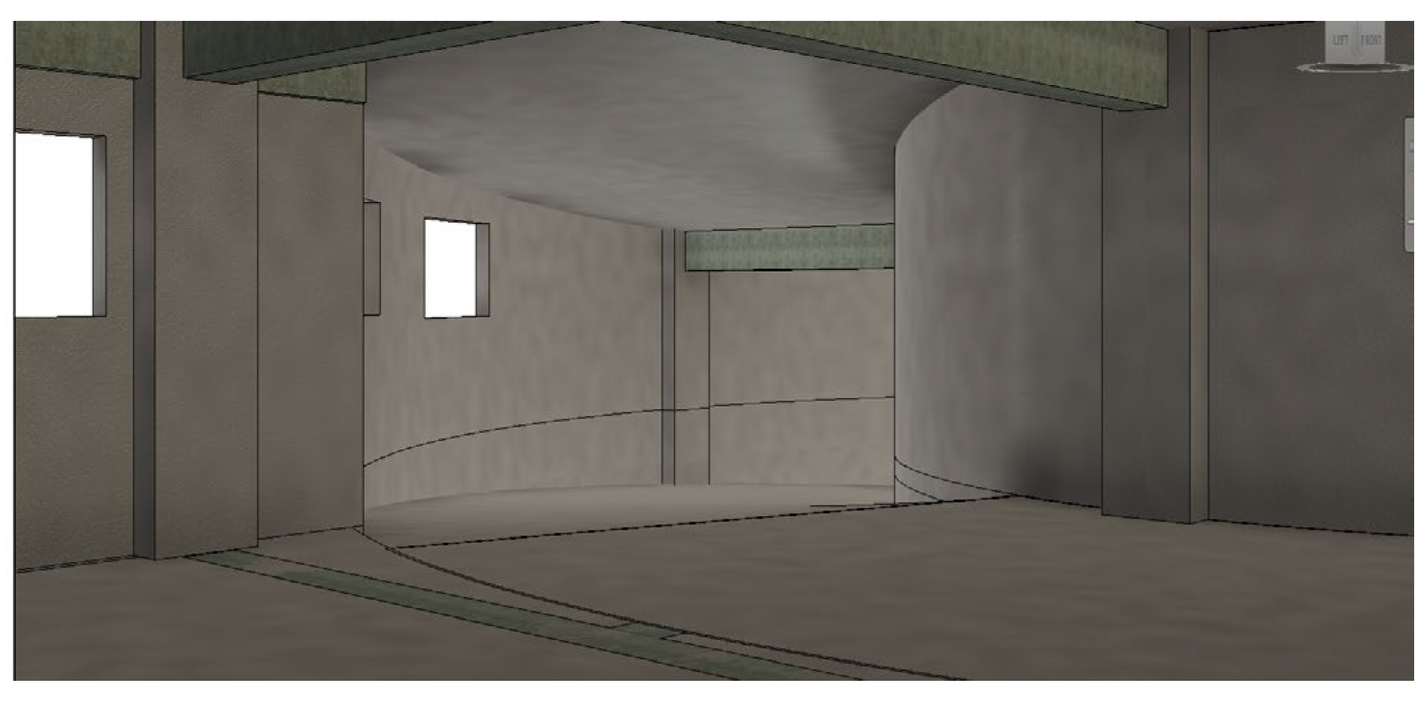
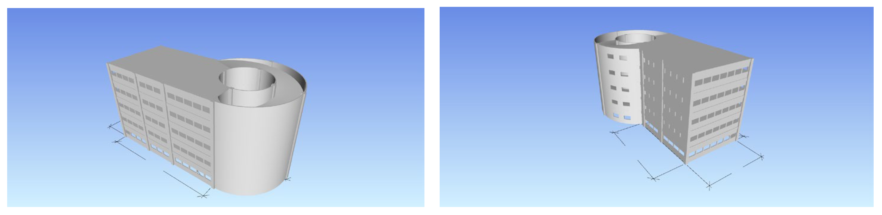
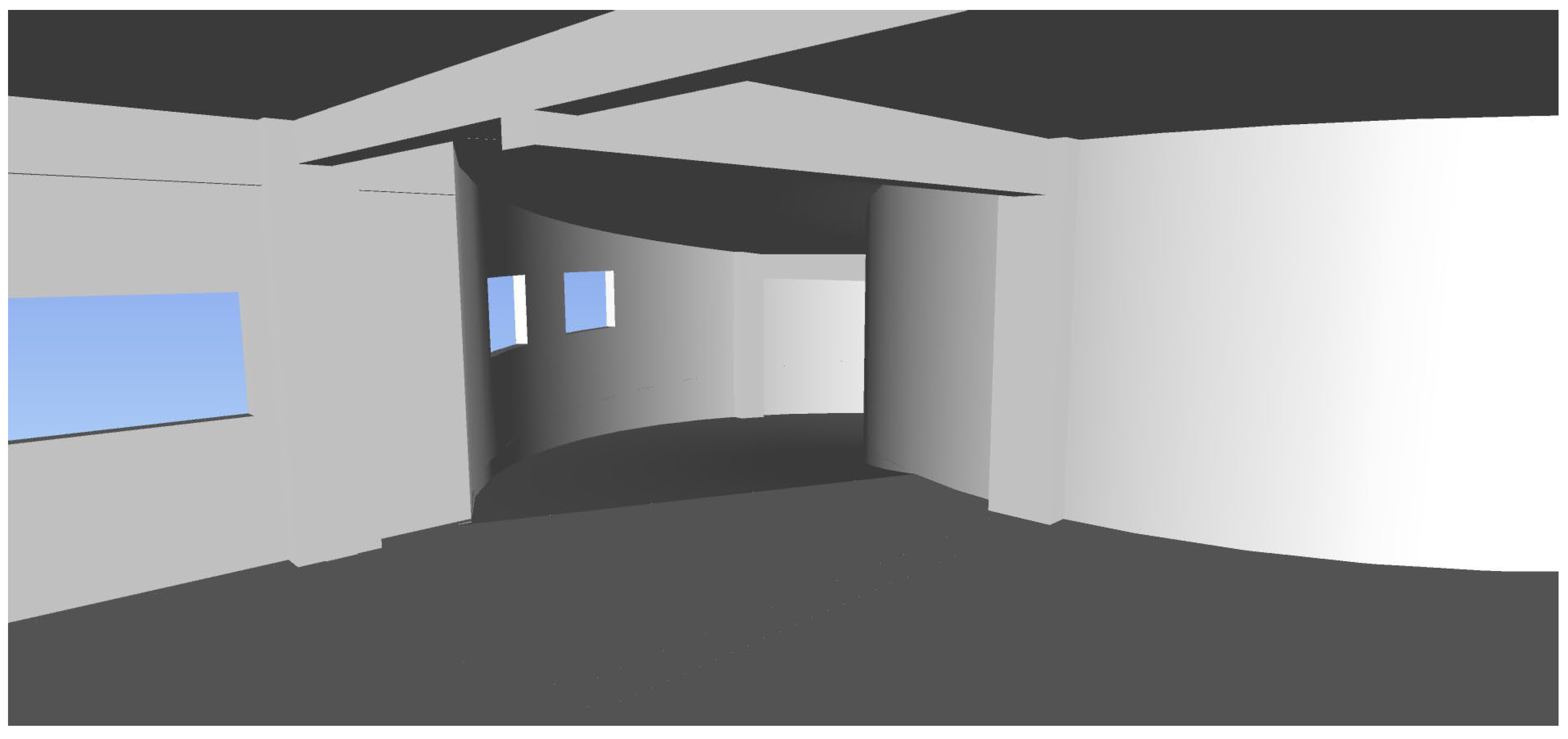
2.1. Irregular Structure System Design via BIM (Revit)

For an irregular structure system such as a ramp or a non-rectangular building, the designer uses a 2D concept layout structure system. When an irregular 3D shape causes a space to be blocked by beams and columns, the Revit BIM 2021 program is used to set up building models. Its most important function is its ramp making tool, as shown in Figure 1. Users can use the function to model a building-floor-height ramp system. Using this function, the ramp floor support beam system locations are defined.

2.2. Code for Car Parking Lot Structures

The building code of Taiwan includes the following regulations.

2.2.1. Car Height Limit

The height of small cars shall not exceed 1.5 times their full width, and their maximum height shall not exceed 2.85 m.

2.2.2. Lane Slope Limit

The slope of the lane shall not exceed one to six, and the surface shall be made of a rough surface or other non-slippery materials. The radius of the inner curve of the lane shall be more than five meters.

2.2.3. Clear Height Restrictions for Fire Pipeline Facilities Limit

When an airtight sprinkler head is installed under a beam, the distance between the return plate and the bottom of the beam shall be less than 10 centimeters, and the distance from the floor or ceiling shall be less than 50 cm.
Thus, we simulated a ramp slope space from bottom to top, as shown in Figure 2.
t a n θ = 1 / X
H m i n = ( 2.85 + h ) s e c θ
  • θ: the slope angle;
  • X : the unit’s height increase in the horizontal dimension;
  • h: the net height from the car top.
By using Equation (2), we simulated the space from a car top of h = 0.15 m, h = 0.5 m, and h = 1 m to obtain the min. space to avoid impact, as shown in Table 1 and Table 2. The different colors mean the clear height fit the design required.

2.2.4. For a Circular Ramp

X = 2 π R
t a n θ = H / X
  • X : the circumference of a circle with a radius R ;
  • H : the building’s height.

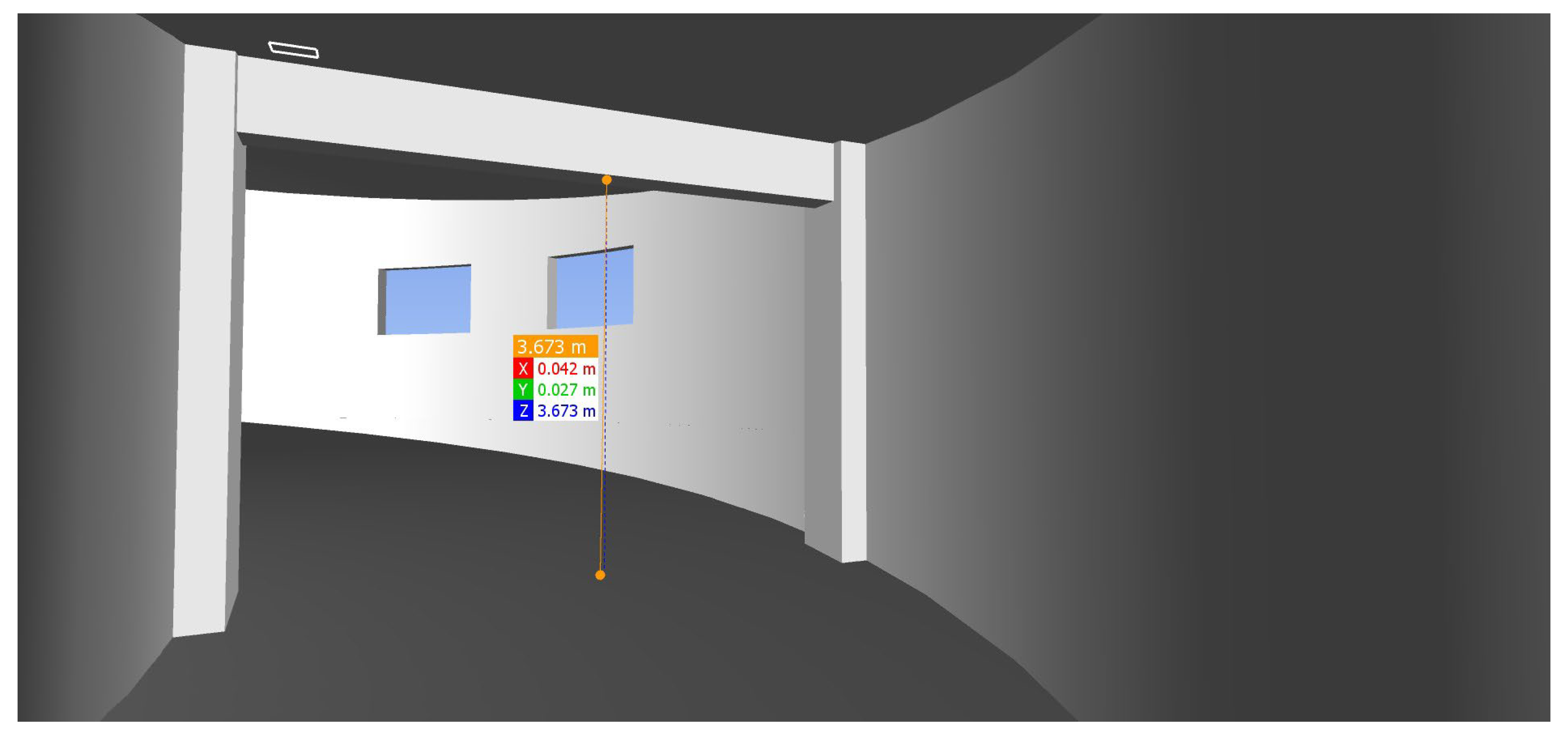
2.3. Navisworks Spatial Conflict Analysis

In AutoDesk Navisworks 2021 software, the model created by the Revit program is exported in an “nwc” format file and then imported into Navisworks to create a spatial model. Navisworks space distance measurement tool is used to measure the x-, y-, and z-axis distances of two spatial points in the design model to obtain the real space distance. Then, users can confirm the design results using codes. In addition, Navisworks also provides a space cruise function. Users can understand the feasibility of the design results through animation and find problems before real construction process.

3. Case Application

The above method was used to analyze a five floor parking lot space as an example. Its plan view is shown in Figure 3. The ramp design coefficients are shown in Figure 4. The building’s north elevation is shown in Figure 5. The N-S and E-W section profiles are shown in Figure 6 and Figure 7. From the profile map, we define the support beam’s real location and set up the support frame system as shown in Figure 8.
In order to define the ramp and plane floor connection and improve the car passing joint comfortableness, we set up a profile map (Figure 9) to discuss the joint function detail sections. To understand the effect of sunlight, we used Revit to simulate the effect to discuss an energy-reducing design (Figure 10).
Then, we transferred the model to AutoDesk Navisworks 2021 software, and the whole building model is shown in Figure 11. We simulated the structure system design as shown in Figure 12.
Then, we used a roaming function to traverse the building model and measured the spatial two point distance to obtain the net height space in the structure system (Figure 13). The ramp width was also obtained, as shown in Figure 14. In Figure 13 and Figure 14 red green and blue box mean the measure results for x, y, z axis distance.

4. Conclusions

From the above analysis, the following conclusions were made from a real-case application.
The combination of the Autodesk Revit and Autodesk Navisworks programs provides a real simulation for the actual structure system’s spatial relationships. Through a spatial analysis of the structural system, it can avoid unreasonable design results. A design combined with BIM and a Navisworks simulation provides the a reasonable structure system and improves architectural lighting and the building’s energy savings.

Funding

This research received no external funding.

Institutional Review Board Statement

Not applicable.

Informed Consent Statement

Informed consent was obtained from all subjects involved in the study.

Data Availability Statement

The data that support the findings of this study are available on request from the corresponding author, upon reasonable request.

Conflicts of Interest

The author declares no conflict of interest.

References

  1. Fazil, S.M.; Sultan, C.R.; Kumar, P.N. Planning and scheduling of residential building using MS project and BIM. Int. Res. J. Eng. Technol. 2021, 8, 1473–1479. [Google Scholar]
  2. Latiffi, A.A.; Mohd, S.; Kasim, N.; Fathi, M.S. Building Information Modeling (BIM) Application in Malaysian Construction Industry. Int. J. Constr. Eng. Manag. 2013, 2, 1–6. [Google Scholar]
  3. Xu, Y.; Zhang, J.; Li, D.; Ao, C. BIM Model Integration of Concrete and Steel Structures in Assembled Substations. Adv. Comput. Sci. Res. 2019, 91, 65–70. [Google Scholar]
Figure 1. Revit’s ramp-making function.
Engproc 55 00093 g001
Figure 2. Net height for parking lot ramp.
Engproc 55 00093 g002
Figure 3. Revit’s structure system.
Engproc 55 00093 g003
Figure 4. Parking lot ramp design coefficient.
Engproc 55 00093 g004
Figure 5. North vertical section map.
Engproc 55 00093 g005
Figure 6. Profile for N-S section.
Engproc 55 00093 g006
Figure 7. Profile for E-W section.
Engproc 55 00093 g007
Figure 8. 3D Structure system render effect for parking lot in Revit.
Engproc 55 00093 g008
Figure 9. Details of the ramp section interaction of the building floor.
Engproc 55 00093 g009
Figure 10. Map for sunlight rendering effect in building.
Engproc 55 00093 g010
Figure 11. Navisworks 3D building view.
Engproc 55 00093 g011
Figure 12. Internal space view result in Navisworks.
Engproc 55 00093 g012
Figure 13. Space net height measurement in Navisworks.
Engproc 55 00093 g013
Figure 14. Ramp width measurement in Navisworks.
Engproc 55 00093 g014
Table 1. Straight ramp slope: net height calculation.
H (Rise) (m)X (m)θ (deg)Hmin = 3.85/cos(θ)Hmin = 3.35/cos(θ)Hmin = 3/cos(θa)
169.4623 3.9031 3.3962 3.0414
178.1301 3.8891 3.3840 3.0305
187.1250 3.8800 3.3761 3.0233
196.3402 3.8737 3.3706 3.0185
1105.7106 3.8692 3.3667 3.0150
Table 2. Circular ramp slope: net height calculation.
H (m)R (m)θ (deg)Hmin = 3.85/cos(θ)Hmin = 3.35/cos(θ)Hmin = 3/cos(θ)
3.5122.6577776333.8541 3.3536 3.0032
3.5132.4535934413.8535 3.3531 3.0027
3.5142.2785285763.8530 3.3526 3.0024
3.5152.1267711363.8527 3.3523 3.0021
4123.0367937793.8554 3.3547 3.0042
4132.8035824383.8546 3.3540 3.0036
4142.6036126863.8540 3.3535 3.0031
4152.4302540363.8535 3.3530 3.0027
5123.7939957853.8584 3.3573 3.0066
5133.5029067923.8572 3.3563 3.0056
5143.2532571863.8562 3.3554 3.0048
5153.0367937793.8554 3.3547 3.0042
Disclaimer/Publisher’s Note: The statements, opinions and data contained in all publications are solely those of the individual author(s) and contributor(s) and not of MDPI and/or the editor(s). MDPI and/or the editor(s) disclaim responsibility for any injury to people or property resulting from any ideas, methods, instructions or products referred to in the content.

