
Determination of the Fracture Point for Inconel-718 Using Luder’s Band Method †


Abstract
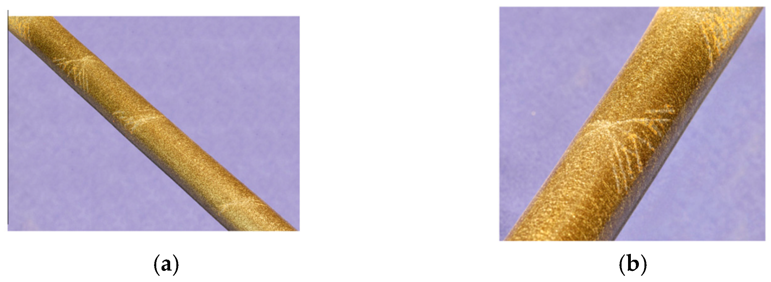
:1. Introduction
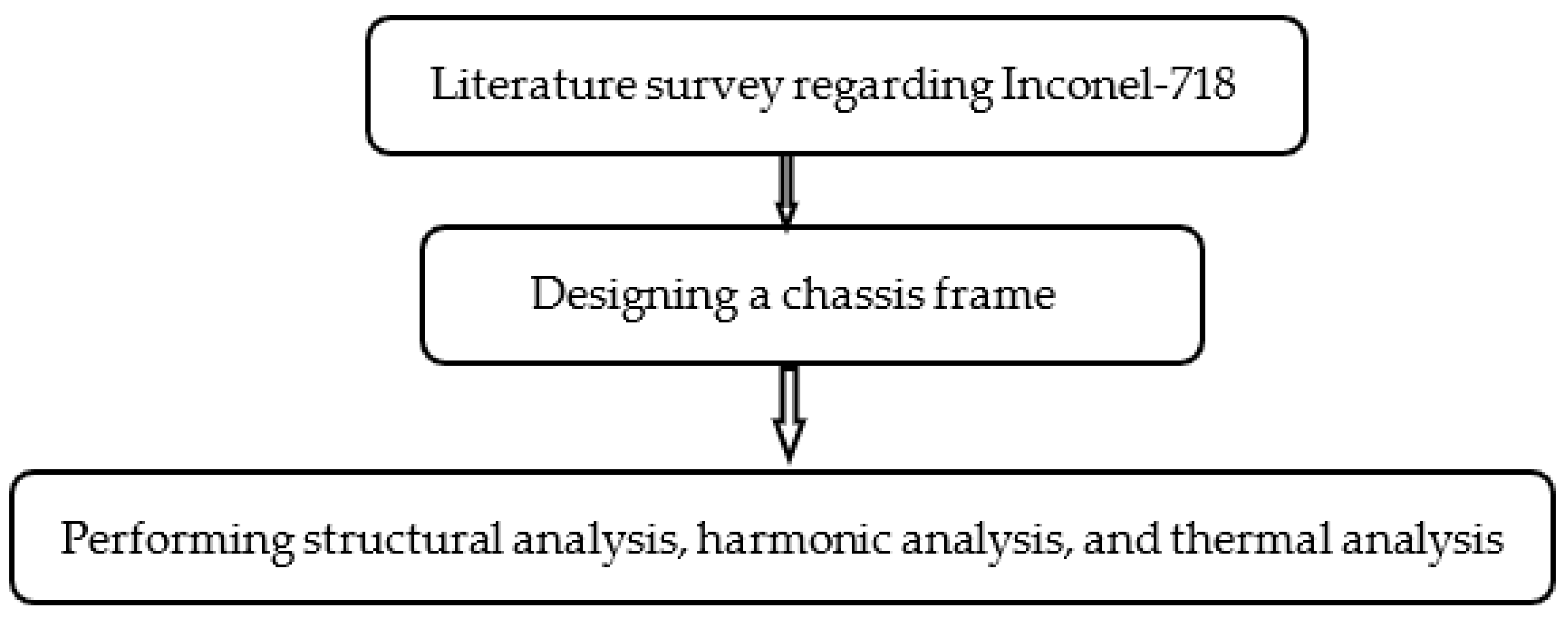
2. Materials and Methods
Methodology
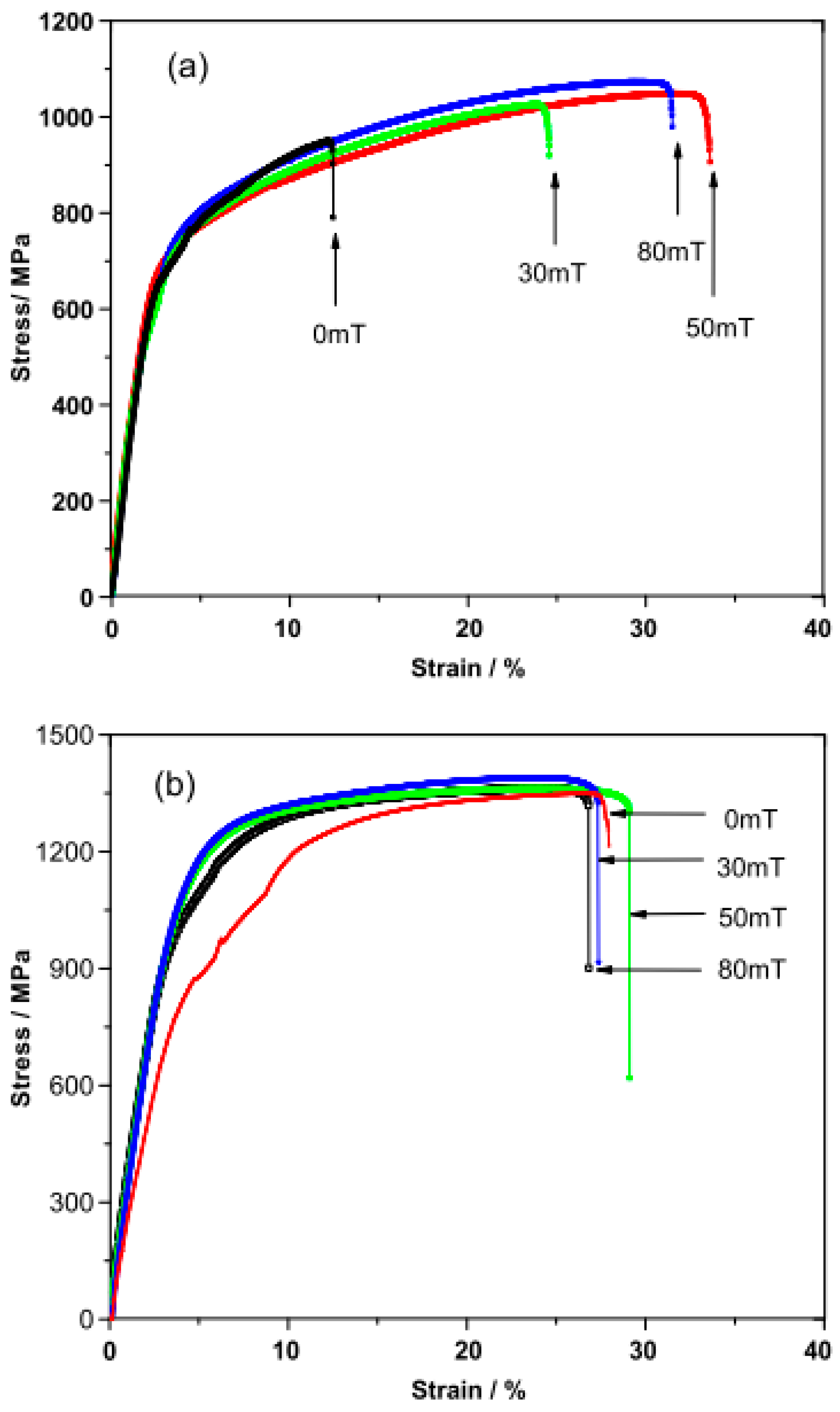
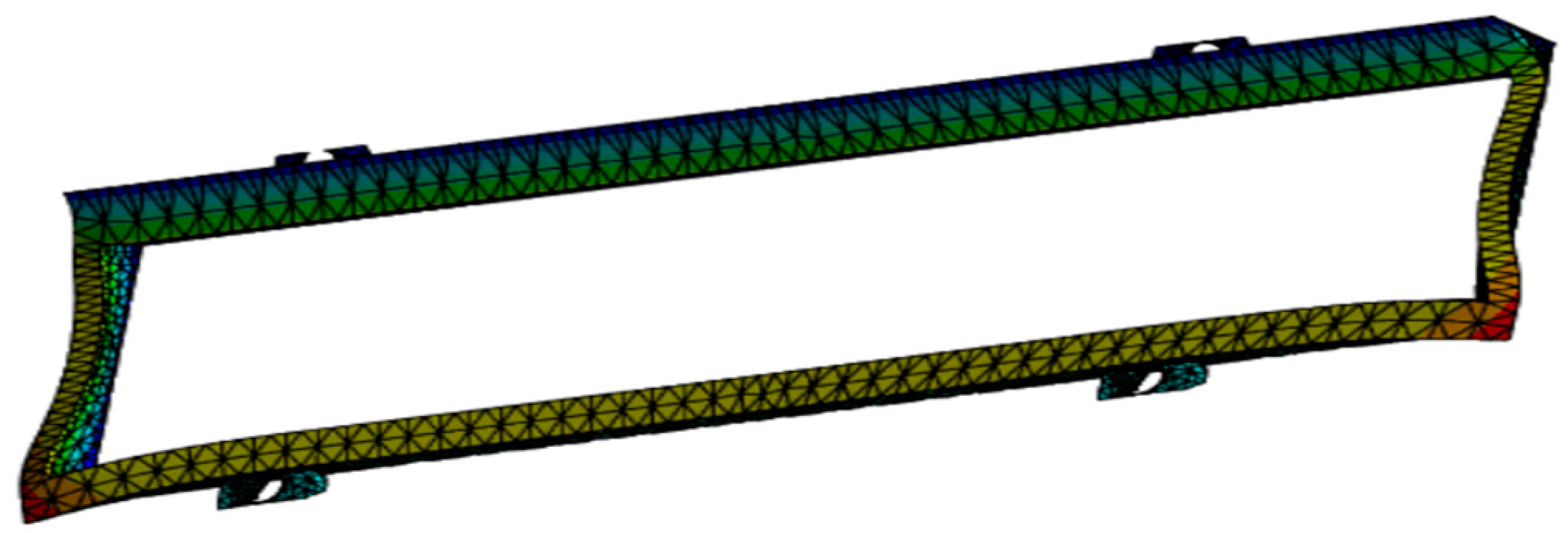
3. Results
3.1. Stress Analysis
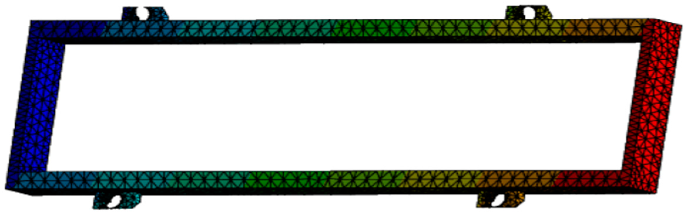
3.2. Harmonic Analysis
3.3. Thermal Analysis
4. Discussion
5. Conclusions
Author Contributions
Funding
Institutional Review Board Statement
Informed Consent Statement
Data Availability Statement
Conflicts of Interest
References
- Luders, W. Über die aeußerung der elasticität an stahlartigen eisenstaben und stahlstäben. Dingler’s Polytecnisches J. 1860, 4, 18–22. [Google Scholar]
- Hallai, J.F.; Kyriakides, S. On the effect of lüders bands on the bending of steel tubes. Part I: Experiments. Int. J. Solids Struct. 2011, 48, 3275–3284. [Google Scholar] [CrossRef]
- Fencheng, F.; Hongmao, C.; Xiaobin, Y.; Guang, Y.; Chunping, H.; Xin, L.; Jing, C. Control of microstructure and mechanical properties of laser solid formed Inconel-718 superalloy by electromagnetic stirring. Opt. Laser Technol. 2017, 99, 342–350. [Google Scholar]
- Eichhubl, P.; John, N.; Hooker; Laubach, S.E. Pure and shear-enhanced compaction bands in Aztec Sandstone. J. Struct. Geol. 2010, 32, 1873–1886. [Google Scholar] [CrossRef]
- Beissel, S.; Belytschko, T. On patterns of deformation in phase transformations and Lüders bands. Int. J. Solids Struct. 1996, 33, 1689–1707. [Google Scholar] [CrossRef]
- Gustafsson, D.; Moverare, J.; Johansson, S.; Hörnqvist, M.; Simonsson, K.; Sjöström, S.; Sharifimajda, B. Fatigue crack growth behaviour of Inconel 718 with high-temperature hold times. Procedia Eng. 2010, 2, 1095–1104. [Google Scholar] [CrossRef]
- Tucho, W.M.; Cuvillier, P.; Sjolyst-Kverneland, A.; Hansen, V. Microstructure and hardness studies of Inconel 718 manufactured by selective laser melting before and after solution heat treatment. Mater. Sci. Eng. A 2017, 689, 220–232. [Google Scholar] [CrossRef]
- Schwab, R. Understanding the complete loss of uniform plastic deformation of some ultrafine-grained metallic materials in tensile straining. Int. J. Plast. 2019, 113, 218–235. [Google Scholar] [CrossRef]
- Chandran, P.A.; Kumar, C.S. Vibration analysis of rotating pre-twisted curved blades under thermal environment. Int. J. Dyn. Control 2023, 11, 919–927. [Google Scholar] [CrossRef]
- Cao, Y.; Zhu, Y.; Ding, W.; Qiu, Y.; Wang, L.; Xu, J. Vibration coupling effects and machining behavior of ultrasonic vibration plate device for creep-feed grinding of Inconel-718 nickel-based superalloy. Chin. J. Aeronaut. 2022, 35, 332–345. [Google Scholar] [CrossRef]
- Brlić, T. Mathematical modeling of the influence parameters during formation and propagation of the Lüders bands. Facta Univ. Ser. Mech. Eng. 2020, 184, 595–610. [Google Scholar] [CrossRef]
- Zuev, L.B.; Barannikova, S.A. Vibrational Kinetics of the Lüders Front. Russ. Phys. J. 2019, 62, 1338–1342. [Google Scholar] [CrossRef]
- Thomas, A.; El-Wahabi, M.; Cabrera, J.M.; Prado, J.M. High-temperature deformation of Inconel-718. J. Mater. Process. Technol. 2006, 177, 469–472. [Google Scholar] [CrossRef]
- Yan, J.; Zhao, R.; Wan, M.; Meng, B. Coupled effect of pulsed current and ultrasonic vibration on deformation behavior of Inconel-718 sheet: Phenomena and modeling. J. Mater. Res. Technol. 2023, 25, 5538–5560. [Google Scholar] [CrossRef]
- Andreotta, R.; Ladani, L.; Brindley, W. Finite element simulation of laser additive melting and solidification of Inconel-718 with experimentally tested thermal properties. Finite Elem. Anal. Des. 2017, 135, 36–43. [Google Scholar] [CrossRef]
- Döleker, K.M.; Erdogan, A.; Yener, T.; Karaoglanlı, A.C.; Uzun, O.; Gök, M.S.; Zeytin, S. Enhancing the wear and oxidation behaviors of the Inconel 718 by low-temperature aluminizing. Surf. Coat. Technol. 2021, 412, 127069. [Google Scholar] [CrossRef]
- Louche, H.; Chrysochoos, A. Thermal and dissipative effects accompanying Lüders band propagation. Mater. Sci. Eng. A 2001, 307, 15–22. [Google Scholar] [CrossRef]
- Agazhanov, A.; Samoshkin, D.A.; Kozlovskii, Y.M. Thermophysical properties of Inconel 718 alloy. J. Phys. Conf. Ser. 2019, 1382, 12175. [Google Scholar] [CrossRef]
- Sweet, J.N.; Roth, E.P.; Moss, M. Thermal conductivity of Inconel 718 and 304 stainless steel. Int. J. Thermophys. 1987, 8, 593–606. [Google Scholar] [CrossRef]
- Lin, Y.C.; Li, K.K.; Li, H.B.; Chen, J.; Chen, X.M.; Wen, D.X. New constitutive model for high-temperature deformation behavior of Inconel 718 superalloy. Mater. Des. 2015, 74, 108–118. [Google Scholar] [CrossRef]
- Schirra, J.J. Effect of heat treatment variations on the hardness and mechanical properties of wrought Inconel 718. Superalloys 1997, 718, 431–438. [Google Scholar]


| Conditions | Position and Values in MPa |
|---|---|
| Fixed support | At the 4 extremes faced |
| Loads | Applied at the 4 extreme corners |
| Pressure (uniformly distributed loading) | 81.5 MPa |
| Condition | Type/Value |
|---|---|
| Environment temperature | 25 °C |
| Fixed support | Hinges |
| Pressure | 7.895 MPa |
| Phase angle | 0° |
| Loaded area | Deformed |
| Condition | Value |
|---|---|
| Initial temperature | 25 °C |
| Heat flow | 89 W |
| Heat Flux | 9 W/mm^2 (ramped) |
Disclaimer/Publisher’s Note: The statements, opinions and data contained in all publications are solely those of the individual author(s) and contributor(s) and not of MDPI and/or the editor(s). MDPI and/or the editor(s) disclaim responsibility for any injury to people or property resulting from any ideas, methods, instructions or products referred to in the content. |
© 2023 by the authors. Licensee MDPI, Basel, Switzerland. This article is an open access article distributed under the terms and conditions of the Creative Commons Attribution (CC BY) license (https://creativecommons.org/licenses/by/4.0/).
Share and Cite
Gupta, A.; Kamath, R.C. Determination of the Fracture Point for Inconel-718 Using Luder’s Band Method. Eng. Proc. 2023, 59, 4. https://doi.org/10.3390/engproc2023059004
Gupta A, Kamath RC. Determination of the Fracture Point for Inconel-718 Using Luder’s Band Method. Engineering Proceedings. 2023; 59(1):4. https://doi.org/10.3390/engproc2023059004
Chicago/Turabian StyleGupta, Arupratan, and Raghavendra C. Kamath. 2023. "Determination of the Fracture Point for Inconel-718 Using Luder’s Band Method" Engineering Proceedings 59, no. 1: 4. https://doi.org/10.3390/engproc2023059004