Proceeding Paper

Static Load Sharing Analysis of a Full Pinion Engagement Planetary Gear Train Based on Statistical Simulation †

by
Vladislav Ivanov
1,* and
Zlatina Tzenova
2
1
Faculty of Mechanical Engineering, Technical University of Sofia, 1756 Sofia, Bulgaria
2
Faculty of Applied Mathematics and Informatics, Technical University of Sofia, 1756 Sofia, Bulgaria
*
Author to whom correspondence should be addressed.
Presented at the 4th International Conference on Communications, Information, Electronic and Energy Systems (CIEES 2023), Plovdiv, Bulgaria, 23–25 November 2023.
Eng. Proc. 2024, 60(1), 3; https://doi.org/10.3390/engproc2024060003
Published: 5 January 2024

Abstract

:
The full pinion engagement planetary gear trains are comparatively little known especially when it comes to the load sharing between the planets. In this paper, an attempt has been made to compensate for the lack of statistical data by extending the lumped mass model with the Monte Carlo simulation, thus generating thousands of different combinations for the pinhole position errors. A normal distribution has been assumed for the random variables. The static load sharing factor and the mesh load factor have been determined for nine scenarios with different mathematical expectations and mean deviations.

1. Introduction

Among the most distinguished features of the planetary gear trains giving them advantages over the non-planetary ones are their lightweight design; their low mass moment of inertia, allowing for high speeds; the possibility of achieving higher manufacturing accuracy of the gears and heat treatment at the same time, which together with the lower pitch velocity leads to lower internal dynamic loads; and the coaxiality of the input and output shaft, which makes them suitable for applications like wind turbines, aircraft engines, etc. These advantages are conditioned by the principle of multi-flow, i.e., theoretically, the power can be split equally between multiple power branches [1,2]. However, the equal load sharing is negatively affected by the presence of a number of manufacturing errors including planet pinhole position errors and pinhole diameter errors, planet tooth thickness errors, planet bore diameter errors, planet bearing needle diameter errors, planet pin diameter errors, pitch line run-outs of the sun gear, and non-equal radial clearances of the planet bearings [1,3,4]. The aforementioned advantages and drawbacks apply for the full pinion engagement PGT from Figure 1 as well. Although the full pinion engagement allows for the theoretically highest potential load split, which makes them suitable for heavy duty applications, the manufacturing and assembly errors could not only cause non-equal load sharing but also could impede the assembly and the proper operation of the gear train. Usually, the models for the load sharing analysis of PGT adopt a deterministic approach when considering the influence of errors [5,6,7,8], which sets certain limitations regarding the generality of the simulation results. In [9], a statistical simulation is used to evaluate the impact of randomly distributed pinhole position errors on the load sharing of a PGT. Zhang and Guo [10] propose a methodology which combines a Monte Carlo simulation and a response surface method for the uncertainty analysis of tooth modifications in helical planetary gear trains. Ref. [11] analyzes the effect of tooth thickness error uncertainty on the working characteristics of planetary gear trains. In the present paper, a stochastic modeling approach is proposed, whereby the lumped mass model for the static load sharing analysis of a full pinion engagement planetary gear train is extended with a Monte Carlo simulation, which allows for the accounting of the random nature of the pinhole position errors.

2. A lumped Mass Model of a Full Pinion Engagement Planetary Gear Train

2.1. Main Assumptions

The model of the planetary gear train will be built in accordance with the following assumptions:
  • Since the model will be used for static load sharing analysis, the damping effect will be neglected;
  • All components of the gear train will be considered as being rigid except for the tooth mesh and the bearings, which will be modeled as lumped linear springs;
  • The tooth mesh stiffness will be considered to be time-invariant;
  • The frictional forces acting in the gear meshing will be neglected;
  • The random pinhole tangential and radial position errors will be considered and included in the force vector of the model. The rest of the manufacturing and assembly errors will be neglected;
  • The system will have three degrees of freedom—translation in x and y directions and rotation ϴj (j = s, r, p, c).

2.2. Building the Model

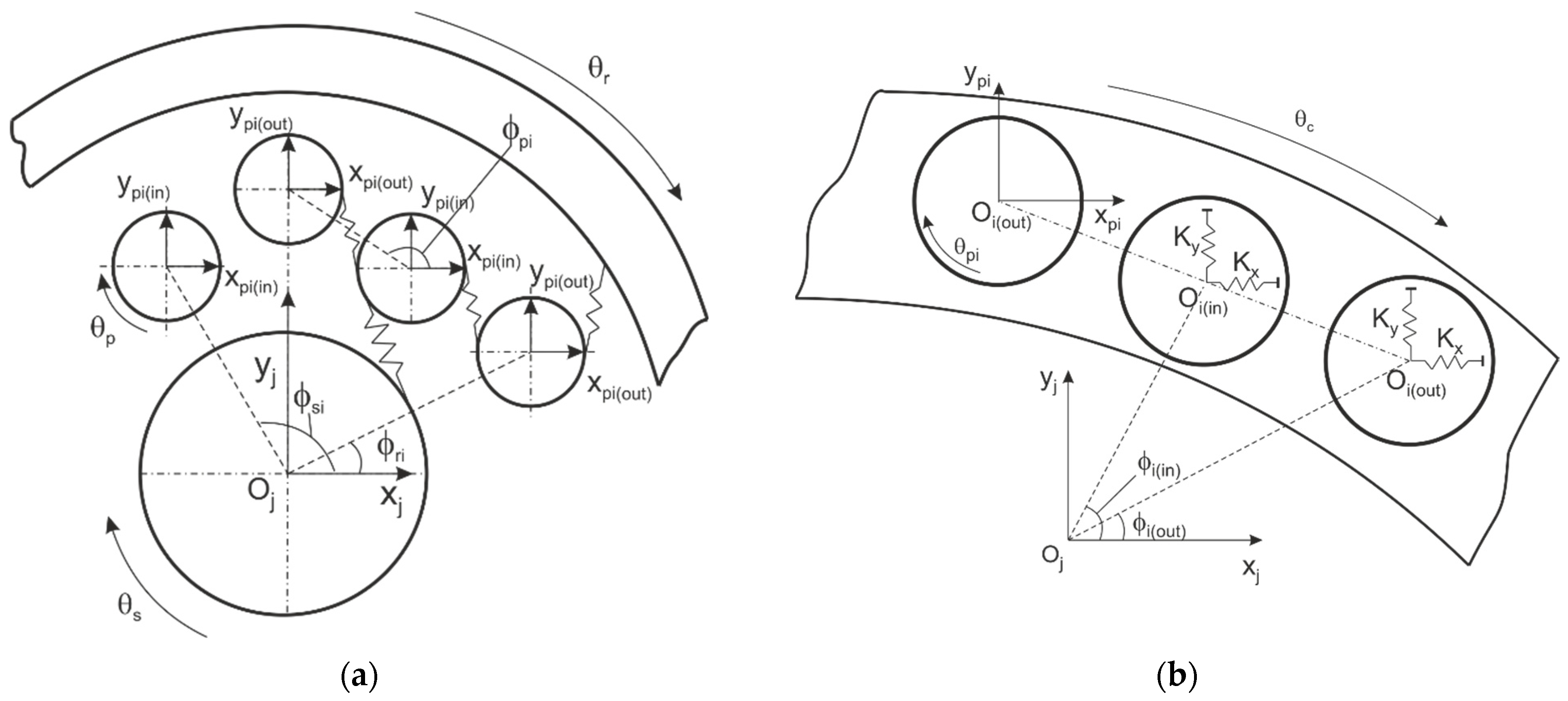
The planetary gear train under consideration includes three central elements, namely a sun gear, a ring gear, and a carrier, and twelve planets, forming a closed loop (Figure 1). Six of the planets mesh with the sun gear and six with the ring gear, i.e., there are three different gear pairs—two external and one internal. Figure 2a illustrates the gear pairs with ϕji (j = s, r, p) as a position angle of the pinion relative to the central gears and to the neighbouring ones, respectively.
In this particular model, the pins are considered to be non-deformable; therefore, the coupling between the planets and the carrier includes only the spring stiffnesses ky and kx, which represent the planet bearings (Figure 2b).
As already stated, the model will be used for static analysis; therefore, the equations of motion can be given in matrix form as follows:
K + K b X = F m
where K is the mesh stiffness matrix, Kb is the central element’s support stiffness matrix, X is the displacement vector, and Fm is the mean force vector.
With three central elements and twelve planets, the model will have 45 degrees of freedom and will be built according to the approach presented in [5,6].
The mesh stiffness matrix has the following form:
K = S 0 0 K s 1 12 0 K s 11 0 0 R 0 0 K r 2 12 0 K r 12 12 0 0 C K BC 1 12 K BC 2 12 K BC 11 12 K BC 12 12 K s 1 12 0 K BC 1 21 P 1 K pp 1 2 12 0 K pp 1 12 12 0 K r 2 12 K BC 2 21 K pp 1 2 12 P 2 0 0 K s 11 12 0 K BC 11 21 0 0 P 11 K pp 11 12 12 0 K r 12 12 K BC 12 21 K pp 1 12 12 0 K pp 11 12 12 P 12 ,
where
S = i = 1 6 K si 11 ; R = i = 1 6 K ri 11 ; C = i = 1 12 K BCi 11 ;
P 1 = K s 1 22 + K pp 1 2 11 + K pp 1 12 11 + K BC 1 22 ;
P 2 = K pp 1 2 22 + K pp 3 2 22 + K r 2 22 + K BC 2 22 ;
P 11 = K s 11 22 + K pp 11 10 11 + K pp 11 12 11 + K BC 11 22 ;
P 12 = K pp 11 12 22 + K pp 1 12 22 + K r 12 22 + K BC 12 22 ;
K si 11 , K si 12 , K si 22 —sun gear/inner planet mesh sub-matrices;
K ri 11 , K ri 12 , K ri 22 —ring gear/outer planet mesh sub-matrices;
K ppi n 11 , K ppi n 12 , K ppi n 22 —inner planet/outer planet mesh sub-matrices;
K BCi 11 , K BCi 12 ,   K BCi 21 , K BCi 22 —carrier/pinion support stiffness sub-matrices.
The element meshing stiffness matrices can be defined as
K si ( E ) = k spi   · V · V T ;
K ri ( E ) = k rpi   · V · V T ;
K ppi n ( E ) = k ppi   · V · V T ,
where k jpi is the mean gear mesh stiffness (j = s, r, p) and V is the projection vector of the mesh line in the central coordinate system. For the sun gear–inner planet pair the projection vector is
V = cos ψ spi   sin ψ spi 1     cos ψ spi   sin ψ spi 1 .
For the ring gear–outer planet pair the projection vector is
V = cos ψ rpi   sin ψ rpi   1   cos ψ rpi sin ψ rpi 1 ,
and for the inner planet–outer planet pair the projection vector is defined as follows:
V = cos ψ ppi   sin ψ ppi   1   cos ψ ppi sin ψ ppi   1
The sub-matrices defining the coupling between carrier and planets are
K BCi ( in / out ) 11 = k y 0 k y c ϕ i ( in / out ) 0 k x k x s ϕ i ( in / out ) k y c ϕ i ( in / out ) k x s ϕ i ( in / out ) k x s 2 ϕ i ( in / out ) + k y c 2 ϕ i ( in / out ) ;
K BCi ( in / out ) 12 = k y 0 0 0 k x 0 k y c ϕ i ( in / out ) k x s ϕ i ( in / out ) 0 ;
K BCi ( in / out ) 21 = K BCi ( in / out ) 12 T ;
K BCi ( in / out ) 22 = k y 0 0 0 k x 0 0 0 0 ,
where “c” stands for the trigonometric function “cos” and “s” for “sin”. ϕ i ( in / out ) is the theoretical angle at which the pinion i is mounted on the carrier.
The angle ψji (j = s, r, p) between the pressure line and the y axis for the different couples is defined as follows:
ψsi = ϕsi − αsi;
ψppi = ϕppi + αppi;
ψri = ϕri − αri,
where αsi/ppi/ri is the pressure angle.
The central elements’ support stiffness matrix is given by
K b = Diag [ K bs K br K bc 0 0 ] ,
where K bj = Diag [ K jy K jx K ju ] , j = s , r , c with K jy , K jx , K ju being the stiffnesses of the linear springs, representing the bearings, which support the central elements of the gear train.
The system displacement vector X includes the displacement vectors qi of the individual gears (sun gear, ring gear, and planets), and the carrier and is defined as follows:
X = q s q r q c q p 1 q p 12 ,   q i = y ji x ji u ji .
The force vector contains the mean torques Tj applied to the central elements and the planet–pin position errors Eti and Eci represented by the vectors Wcpi and Wci, given in [5] as
F m = F sm F rm F cm + W ci W cp 1 W cp 12 ,   F jm = 0 0 T j r j ;
W cpi = k y ( E ci sin ϕ i + E ti cos ϕ i ) k x ( E ci cos ϕ i E ti sin ϕ i ) 0 ;
W ci = k y ( E ci s ϕ i + E ti c ϕ i ) k x ( E ci c ϕ i E ti s ϕ i ) k x ( E ci c ϕ i E ti s ϕ i ) s ϕ i + k y ( E ci s ϕ i + E ti c ϕ i ) c ϕ i .
Unlike the deterministic models, where the values of the planet–pin position errors Eti and Eci are fixed, here, in this model, the values are random and follow a certain statistical distribution.
The load sharing factor LSFn is calculated as
LS F n = q pn i = 1 12 q pi · 100 % ,   q pi = y pi 2 + x pi 2 .

3. The Monte Carlo Simulation

As already mentioned, the results from the deterministic modeling approach, that uses specific values for the manufacturing and assembly errors, lack generality, which limits its applications to particular cases. The stochastic modeling approach on the other hand is based on the generation of thousands of combinations for the random factors under consideration, thus providing statistical information, which can be used for more general purposes.
The lumped mass model, presented in this paper, accounts for the influence of the random pinhole position errors, which are included in the force vector Fm. The type of distribution of the random variables is assumed to be normal.

3.1. Normal Distribution of a Random Variable

The normally distributed random variable x has a mathematical expectation EX = a and standard deviation σX = σ. The probability density is expressed as
f ( x ) = 1 σ 2 π e ( x a ) 2 2 σ 2 ,
and the probability distribution function as
F ( x ) = 1 σ 2 π x e ( x a ) 2 2 σ 2 dx .
A commonly used statistic function is the Laplace function Φ(x):
Φ ( x ) = 1 2 π 0 x e t 2 2 dt .
The probability p that a normally distributed random variable x falls within a certain interval with limits α and β is calculated as follows:
p ( x   <   α ) = 1 2 Φ α a σ + 1 2 ;
p ( α   <   x   <   β ) = 1 2 Φ β a σ Φ α a σ ;
p ( x > β ) = 1 2 1 2 Φ β a σ .
For normally distributed random variables x, the so-called “three sigma” rule applies, i.e., the probability that the variance in the absolute value is less than three times the standard deviation:
p ( x   a < 3 σ ) = Φ 3   0.9973 .
In other words, with probability ≈0.9973, it can be expected that, in absolute value, the random variable x will deviate from its mean value a by no more than 3σ. For 2σ and σ (28) looks as follows:
p ( x   a < 2 σ ) = Φ 2   0.9545 ;
p ( x   a < σ ) = Φ 1   0.68268 .

3.2. A Parametric Study of the Influence of Random Pinhole Position Errors on the Static Load Sharing

The aim of the parametric study is to provide statistical data on the static load distribution between the planets of the full pinion engagement planetary gear train. The random parameters, which represent the random variable x from the above equations, will be the radial and tangential pinhole position errors Eci and Eti. Nine different scenarios will be simulated, with the values for the mathematical expectation a and standard deviation σ given in Table 1. The probability given by (29) will be used.
Scenarios 1, 2, and 3 suggest a distribution centered about a no error condition with different standard deviations depending on the manufacturing processes. According to (28), 95.45% of the position deviations will fall in the interval −0.02 mm ÷ 0.02 mm for scenario 1, −0.01 mm ÷ 0.01 mm for scenario 2, and −0.006 mm ÷ 0.006 mm for scenario 3. The rest of the scenarios suggest an intervention resulting in deviations in one direction only. Following again the 2 σ probability, the position deviations for scenarios 4, 5, and 6 will be, respectively, between 0.004 mm and 0.016 mm, 0.005 mm and 0.025 mm, and 0.06 mm and 0.034 mm. For scenarios 7, 8, and 9, the deviations will fall in the interval −0.016 mm ÷ −0.004 mm, −0.025 mm ÷ −0.005 mm, and, respectively, −0.034 mm ÷ −0.006 mm. Here, the sign “-” stands for deviations in the clockwise direction for the tangential errors and in the direction towards the beginning of the central coordinate system for the radial errors.
The rest of the lumped mass model parameters are as follows:
  • Mesh stiffness: Kspi = Krpi = Kppi = 5.2 × 10⁸ N/m;
  • Support stiffness: Kx = Ky = 5.0 × 10⁸ N/m, Kcu = 1 × 10¹² Nm/rad, Ksu = Kru = 1 × 10⁻⁹ Nm/rad;
  • Transverse pressure angle: αs = αr = αpp = 200.
The fixed element of the gear train will be the carrier; therefore, a high support torsional stiffness will be assigned to it. The low torsional support stiffness values of the other two central elements guarantee the invertibility of the overall stiffness matrix. A total of 80% of the nominal for the gear train torque is applied to the sun gear in the model.

3.3. Simulation Results

With the position deviations of the planets being chosen as random variables for the model, the number of possible combinations will be pN, where N is the number of planets (in the particular model N = 12) and p is the tolerance band. For example, for scenario 1 from Table 1, the tolerance band will be 20 μm, therefore, p = 20. Due to the computing power limitation, the number of combinations will be limited to 10,000.
Equation (20) is used to calculate the load sharing, but for planetary gear trains with inner and outer planets, i.e., the AAI - and especially the full pinion engagement planetary gear trains, which are kinematically equivalent to the AAI - , it gives information only about the load sharing between the pins. The reason for this is the geometric configuration of the inner and outer planets, whereby for the planetary gear train presented in this paper, in the ideal case where there are no manufacturing and assembly errors, the outer pins are subject to bigger deformations than the inner pins. This phenomenon is discussed in [12] and means that in the practical gear trains design, (20) could be useful for dimensioning the planets’ bearings and the pins. In order to expand its applicability and be used for the calculation of the mesh load factor Kγ, which is specified in ISO 6336-1 [13], (20) must be complemented by an equation accounting for the aforementioned peculiarities. Then, the mesh load factor Kγ can be calculated as follows:
K γ   in / out = LSF in / out   max LSF in / out   nom ,
where LSF in / out   max is the maximum value for the inner and outer planets, respectively, calculated according to (21), and LSF in / out   nom is the nominal or ideal load sharing factor considering the geometrically determined unequal distribution of the load inside the gear train. For the nominal load sharing factor we have the following:
LSF in / out   nom = 2 N 1 + L · 100 % ;
LSF out / in   nom = 2 L N 1 + L · 100 % = LSF in / out   nom · L ,
where N is the overall number of planets and L is the coefficient accounting for the load distribution between the inner and outer planets. When L = 1 the load will be equally distributed among all the planets. A value of 1,5 for L means that the pins of the more loaded planets (inner or outer) are subject to a 50% higher load than the less loaded ones. Finally, the mesh load factor Kγ for the whole planetary gear train will be
Kγ = max [Kγ in, Kγ out].
The simulation results are presented in Table 2 in terms of the maximum load sharing factor according to (20) and the mesh load factor according to (33). Since there exist no previous statistical data or experimental results regarding the nominal load sharing factor for the particular gear train, it is calculated using the lumped mass model and assuming an ideal scenario with no pinhole position deviations.
The analysis of the simulation results shows exceptionally high values and minor dependence on the standard deviation σ for the maximum load sharing factors LSF out / in   max as well as for the mesh load factor Kγ for the first three scenarios, suggesting a mathematical expectation a = 0.
The results in the rest of the scenarios are much closer to the results of the experimental investigations conducted on the test rig, which was described in [14]. Although insufficient in amount to allow for generalization, the experimental results with radial and tangential pinhole deviations corresponding to those in scenario 7 show a maximum load sharing factor for the outer planets LSF out   max = 11.9% and for the inner planets LSF in   max   = 7%. This allows one to assume that the simulation model can adequately represent the physical one. The results in Table 2 for scenarios 4–9 clearly show an increase both in the load sharing factors LSFin/out max and the mesh load factors Kγ as the pinhole position deviations increase, which is expected. A very important trend that can be observed in all of the scenarios is that the load sharing factor for the outer planets is higher than the one for the inner planets. This peculiarity was already partially explained and expressed with (31) and (32) and should be considered when dimensioning the planets’ pins and bearings. The values for the mesh load factor Kγ for scenarios 4–9 are in the range of 21% ÷ 29% higher than the ones for six planets AI - gear trains specified in the standards ANSI/AGMA 6123-B06 [15] for accuracy grade A7 and in IEC 61400-4:2012 [16] for wind turbine gearboxes. Due to the lack of data regarding the load sharing in full pinion engagement planetary gear trains, the standards can be used as a reference.
Figure 3 shows the load sharing factor values for the different planets for scenarios 1, 4, and 7 for 5000 pinhole position error combinations. On the vertical axis, the values for the load sharing factor LSFn ranging between 0% and 20% are displayed. The planets’ numbers are placed on the circumference of the graph with odd numbers for the inner planets and even numbers for the outer planets.
When analyzing the graph in Figure 3, it seems that the planets are comparatively equally loaded with LSFn around 13.5% for the inner planets in scenario 1 and 8.5% for scenarios 4 and 7, 18% for the outer planets in scenario 1 and 11.5 ÷ 12% for scenarios 4 and 7. Exceptions are the inner planets 3 and 9 with approximately 23% lower LSFn values and the outer planet 8 with approximately 13% higher load sharing factor. These deviations are due to the fact that the particular lumped mass model is assumed to have a loss of contact between planets 2 and 3 and planets 8 and 9, whereby the corresponding mesh stiffness matrices are zero matrices and the planets have a lower effective support stiffness.

4. Conclusions

In conclusion, it is worth noting that the unusually high values for the load sharing factors LSF out / in   max and for the load mesh factor Kγ in the first three scenarios, suggesting a mathematical expectation a = 0, could mean that a distribution of the values for the radial and tangential pinhole deviations centered about the no error condition is the worst case scenario, but could also be an indicator of a model weakness in terms of the formulation of the force vector. Due to the lack of experimentally obtained statistical data, this question stays open. For the rest of the scenarios, the values of the load mesh factor Kγ are comparatively close to the standard ones for AI - planetary gear trains. This allows us to conclude that when combined with statistical tools, the lumped mass model can provide valuable information on the static load sharing relations in planetary gear trains and especially less-known ones, which is the case with the full pinion engagement planetary gear trains. Another useful application of the statistical simulation is the model validation since it allows for the theoretical realization of thousands of manufacturing error combinations.

Author Contributions

Conceptualization, V.I.; methodology, Z.T.; investigation, V.I. and Z.T.; resources, V.I. and Z.T.; writing—original draft preparation, V.I.; writing—review and editing, Z.T.; visualization, V.I.; funding acquisition, V.I. All authors have read and agreed to the published version of the manuscript.

Funding

This research was funded by the Research and Development Sector at the Technical University of Sofia, grant number 231ИП0019-06.

Institutional Review Board Statement

Not applicable.

Informed Consent Statement

Not applicable.

Data Availability Statement

The data presented in this study are available on request from the corresponding author. The data are not publicly available due to privacy restrictions.

Acknowledgments

The authors would like to thank the Research and Development Sector at the Technical University of Sofia for the financial support.

Conflicts of Interest

The authors declare no conflicts of interest.

References

  1. Arnaudov, K.; Karaivanov, D. Planetary Gear Trains; Taylor & Francis Group, LLC: Milton Park, UK, 2019. [Google Scholar]
  2. Arnaudov, K.; Karaivanov, D.; Dimitrov, L. Some practical problems of distribution and equalization of internal loads in planetary gear trains. Mech. Mach. Sci. 2013, 13, 585–596. [Google Scholar]
  3. Bodas, A.; Kahraman, A. Influence of carrier and gear manufacturing errors on the static load sharing behavior of planetary gear sets. JSME Int. J. Ser. C 2004, 47, 908–915. [Google Scholar] [CrossRef]
  4. Tsai, S.-J.; Hwang, G.-L.; Yeh, S.-Y. An Analytical Approach for Load Sharing Analysis of Planetary Gear Drives. In Proceedings of the 13th World Congress in Mechanism and Machine Science, Guanajuato, Mexico, 19–25 June 2011. [Google Scholar]
  5. Kahraman, A. Load Sharing Characteristics of Planetary Transmissions. Mech. Mach. Theory 1994, 29, 1151–1165. [Google Scholar] [CrossRef]
  6. Inalpolat, M.; Kahraman, A. A dynamic model to predict modulation sidebands of a planetary gear sets having manufacturing errors. J. Sound Vib. 2010, 329, 371–393. [Google Scholar] [CrossRef]
  7. Liu, W.; Li, J.; Kang, Y.; Liu, Y.; Xu, X.; Dong, P. Load Sharing Behavior of Double-Pinion Planetary Gear Sets Considering Manufacturing Errors. IMMAEE 2019. In Proceedings of the IOP Conf. Series: Materials Science and Engineering, Kazimierz Dolny, Poland, 21–23 November 2019; Volume 677. [Google Scholar]
  8. Wei, J.; Zhang, A.; Qin, D.; Lim, T.; Shu, R.; Lin, X.; Meng, F. A coupling dynamics analysis method for a multistage planetary gear system. Mech. Mach. Theory 2016, 110, 27–49. [Google Scholar] [CrossRef]
  9. Singh, A. Epicyclic load sharing map—Application as a design tool. In Proceedings of the American Gear Manufacturers Association Fall Technical Meeting, Cincinnati, OH, USA, 30 October–1 November 2011; pp. 55–79. [Google Scholar]
  10. Zhang, J.; Guo, F. Statistical modification analysis of helical planetary gears based on response surface method and Monte Carlo simulation. Chin. J. Mech. Eng. 2015, 28, 1194–1203. [Google Scholar] [CrossRef]
  11. Diez-Ibarbia, A.; Sanchez-Espiga, J.; Fernandez-del-Rincon, A.; Calvo-Irisarri, J.; Iglesias, M.; Viadero, F. Probabilistic analysis of the mesh load factor in wind-turbine planetary transmissions: Tooth thickness errors. Mech. Mach. Theory 2023, 185, 105341. [Google Scholar] [CrossRef]
  12. Alexandrov, A.; Ivanov, V. The influence of planet position on axle loads in double planet planetary gear trains. Eng. Proc. 2023, 41, 3. [Google Scholar]
  13. ISO 6336-1:2019; Calculation of Load Capacity of Spur and Helical Gears. Basic Principles, Introduction and General Influence Factors. International Organization for Standardization: Geneva, Switzerland, 2006.
  14. Ivanov, V.; Aleksandrov, A.; Tsonev, V.; Kuzmanov, N.; Troha, S.; Dimitrov, L. The effect of external forces on the load sharing of a full planet engagement planetary gear train. In Proceedings of the 2022 International Conference on Communications, Information, Electronic and Energy Systems (CIEES 2022), Veliko Tarnovo, Bulgaria, 24–26 November 2022. [Google Scholar]
  15. ANSI/AGMA 6123-B06; Design Manual for Enclosed Epicyclic Gear Drives. American Gear Manufacturers Association: Alexandria, Virginia, 2016.
  16. IEC 61400-4:2012; Design Requirements for Wind Turbine Gearboxes. International Electrotechnical Commission: Geneva, Switzerland, 2012.
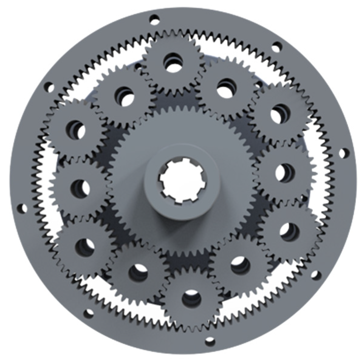
Figure 1. Full pinion engagement planetary gear train with 12 planets.
Engproc 60 00003 g001
Figure 2. Lumped mass model of (a) sun–inner planet, inner planet–outer planet, and ring–outer planet pairs; (b) carrier–planets pairs.
Engproc 60 00003 g002
Figure 3. Load sharing factor LSFn with Φ 2 0.9545 .
Engproc 60 00003 g003
Table 1. Mathematical expectation and standard deviation of Eci and Eti.
Scenario NumberMathematical Expectation
a [mm]
Standard Deviation
σ [mm]
100.010
200.005
300.003
40.0200.007
50.0150.005
60.0100.003
7−0.0200.007
8−0.0150.005
9−0.0100.003
Table 2. Simulation results in terms of maximum load sharing factor and mesh load factor.
Scenario NumberLSFin max [%]LSFout max [%]Kγ
118.021.53.50
217.721.53.50
318.021.03.50
48.012.91.75
58.313.11.80
68.513.21.84
78.412.61.77
88.612.91.82
98.813.01.86
Disclaimer/Publisher’s Note: The statements, opinions and data contained in all publications are solely those of the individual author(s) and contributor(s) and not of MDPI and/or the editor(s). MDPI and/or the editor(s) disclaim responsibility for any injury to people or property resulting from any ideas, methods, instructions or products referred to in the content.