Abstract
In the manufacturing sector, there is a constant effort to improve procedures to produce high-quality goods at a lower cost. Academics are improving aspects of the metal machining process to increase efficiency. New techniques have been developed to achieve this, utilizing better production procedures and more advanced technological tools. It is essential to optimize production processes and minimize their negative impact on the environment and human health. Therefore, environmentally friendly machining operations, such as minimal quantity lubrication (MQL) machining, are being implemented. MQL is used in metal removal processes like milling, drilling, and turning to reduce the use of cutting fluids. The effectiveness of MQL can be improved by misting the flank face and the area near the chip tool contact. A turning center suitable for MQL configuration has been developed as part of the current research project. During the turning of Inconel 718 under dry, conventional fluid, and conventional fluid under MQL process conditions, forces and surface roughness data were examined.
1. Introduction
Compared to titanium alloy, Inconel 718 is a strong material that keeps its strength even when heated. Because of this, it is used in the manufacturing, petrochemical, and aerospace industries, among others [1,2]. The temperature in the shear zone rises as a result of the material’s poor machinability. The temperature harms the longevity of the tool. MQL is one technique of this kind that not only reduces the temperature that is caused by the evaporation of very small droplets and the forced convection of the compressed air, but it also has a low impact on the natural environment and is economical. Davim et al. [3] turned brass using MQL and flood cooling, and they said that MQL could replace flood cooling completely.
They did this by carrying out the turning of brass. According to the findings of [3,4], MQL yields superior results for all types of materials and can be utilized fruitfully in manufacturing processes such as milling, drilling, grinding, and turning. Using three different coated carbide inserts, [5] investigated the effect of MQL on tool life and surface finish during the machining of Inconel718 alloy. They discovered that MQL reduced tool life. Ref. [6] examined how the machining environment and the machining process factors affected the alloy Inconel718’s surface quality. To assess the performance of several coated carbide tools when turning super alloys in both dry and MQL environments, ref. [7] experimented.
In both conditions that were examined, it was found that coated carbide tools performed noticeably better than uncoated carbide tools. Experiments have been performed with the manufactured nozzle, and the results have been examined in wet, MQL, and dry settings, respectively. The super alloy Inconel718 was utilized as the work material, while TiAlN-coated inserts were put to use as the cutting tool.
2. Materials and Methods
2.1. Set Up Design of MQL Machining
In MQL, the design of the mist generator is extremely important because it determines the concentration of the mist as well as the size of the particles. A nozzle that has been given careful consideration in its design is the key source of motivation for this study.
2.1.1. Design of Nozzle
As was also mentioned earlier, the nozzle in question must be able to do the following things for the application at hand: oil must flow smoothly and continuously through the nozzle and out of its outlet, and it must also move fast enough to reach all of the machining interfaces. Several of the design parameters that are not as relevant in the current field of study have been maintained to maintain consistency with designs that are readily available locally and simpler to construct. The purpose of doing this was to keep the research’s integrity.
2.1.2. Internal Nozzle
However, a nozzle that begins with a section that is converging, then transitions to a section that is diverging, and is then separated by a throat that has the smallest possible cross-section, can increase the air jet velocity at the exit to a value that is significantly greater than Mach 1. This is because the nozzle’s throat has the smallest cross-sectional area feasible. Additionally, the high-velocity air jet’s turbulence will enhance its ability to atomize the oil particles into ever-tinier pieces. The equations used to calculate the internal nozzle’s throat and exit cross-sectional areas are summarized below.
These equations were used under the presumption that the air stream’s flow behavior was idealized adiabatic. This approximation is quite precise and ought to be used, even though it is based on a fluid flow speed that is substantially faster. The air that comes in through the intake is said to be stagnant, which means that its velocity is zero. Let the properties of the inlet, also known as stagnation, be determined by the subscript “0”, the throat’s characteristics by the subscript “t”, and the exit’s characteristics by the subscript “e”.
Steady Flow Energy Equation (SFEE).
2.1.3. External Nozzle
The external nozzle was constructed with the aforementioned factors in mind, and the geometrical dimensions of the nozzle may be found in Table 1.

Table 1.
Geometrical dimension of nozzle.
2.1.4. Cap
The design of the cap makes it easy to connect and disconnect the external and internal nozzles when needed. The geometrical dimensions of the cap can be found in Table 1.
2.2. Material Choice for the Nozzle and Strength
The reliability of the nozzle, as well as its durability, performance, and wear life, are all dependent on selecting the appropriate material. When all of these factors were considered, brass was found to have a perfect combination of the qualities. The measurements could be accurate to the micron scale.
2.3. Experimental Conditions
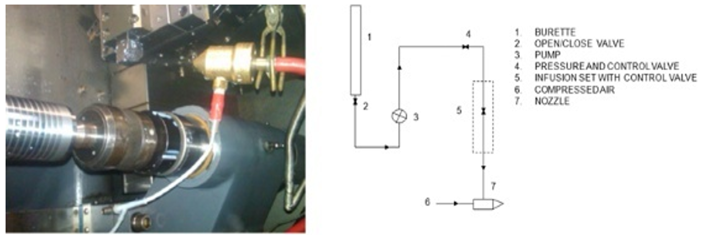
As indicated in Figure 1, the mist is sprayed with a nozzle onto the rake face from the outside that is installed close to the machining zone. In the current set of trials, a circular bar made of Inconel 718 measuring 100 mm in diameter and 300 mm in length was turned.
Figure 1.
CNC turning center with MQL arrangement and block diagram of MQL setup.
Tests were carried out in a CNC turning center in a variety of conditions, including dry, wet, and MQL. In each of the experiments, a new insert was utilized to turn the length of the workpiece measuring 20 mm. The surface roughness was determined with the assistance of a surface profilometer, and a tool force piezoelectric dynamometer was used to measure the forces.
3. Results and Discussion
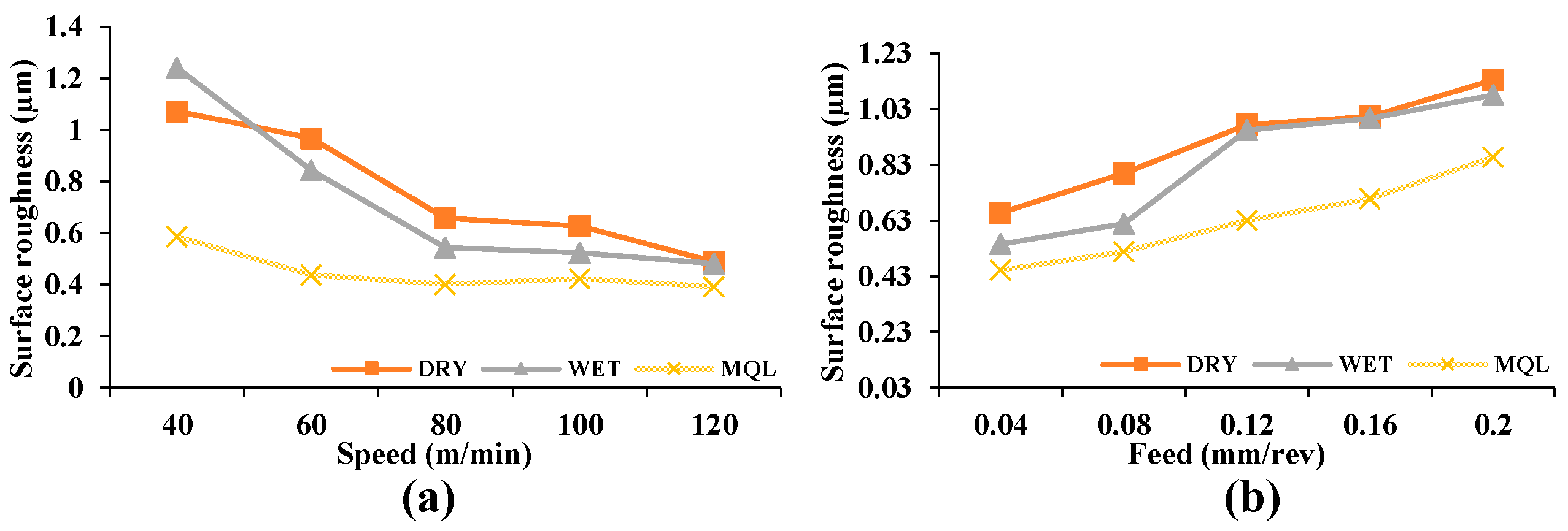
Figure 2 illustrates the difference in surface roughness that occurs when the feed rate and cutting speed are changed while maintaining a depth of cut of 0.5 mm in a variety of settings. When compared to dry cutting, the MQL cutting method results in a 15–40% reduction in surface roughness.
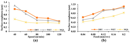
Figure 2.
(a) Increase in surface roughness with a feed rate of 0.04 mm/rev, (b) roughness of the surface as the feed is increased at 80 m/min of cutting speed.
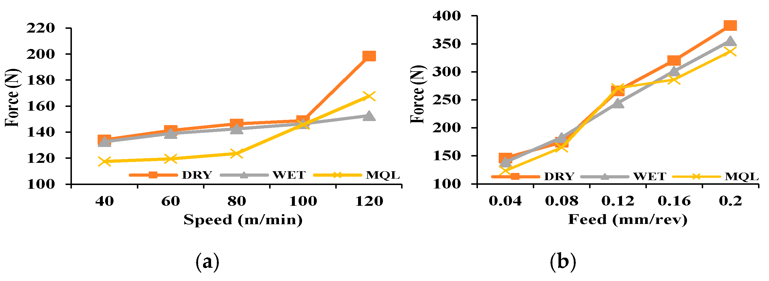
Figure 3, shows variation of cutting force with feed. Because of the short length of the cut (20 mm), there is not much variance in nose wear, as can be seen clearly in Figure 4.
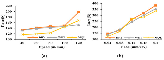
Figure 3.
(a) Tangential cutting force with feed increase at a feed rate of 0.04 mm/rev, and (b) feed increase at a feed rate of 80 m/min.

Figure 4.
Nose wear at different modes at a speed of 120 m/min and feed 0.04 mm/rev.
4. Conclusions
Inconel 718 was turned through a process in an MQL environment using a freshly built setup. In MQL conditions, the alloy displayed an improvement in its cutting capability. It has been discovered that MQL is more effective at slower cutting speeds, which may be because it has a greater potential for penetrating the chip–tool interface. However, when the cutting speed increased, the impact of MQL became less pronounced. This occurred as a result of the chip–tool contact area becoming more plasticized, making it more difficult for the mist to penetrate the substance efficiently. The results of the current trials determined that subjecting the Inconel alloy to MQL conditions improved its overall machining performance.
Author Contributions
Conceptualization, B.C.B. and K.M.; methodology, B.C.B.; validation, B.C.B. and K.M.; formal analysis, A.M.; investigation, B.C.B.; resources, K.M.; data curation, B.C.B.; writing—original draft preparation, B.C.B.; writing—review and editing, K.M. and A.M; visualization, B.C.B.; supervision, K.M.; project administration, K.M.; funding acquisition, A.M. All authors have read and agreed to the published version of the manuscript.
Funding
This research received no external funding.
Institutional Review Board Statement
Not applicable.
Informed Consent Statement
Not applicable.
Data Availability Statement
All data are provided in the article.
Conflicts of Interest
The authors declare no conflict of interest.
References
- Baldonado, M.; Chang, C.-C.K.; Gravano, L.; Paepcke, A. The Stanford Digital Library Metadata Architecture. Int. J. Digit. Libr. 1997, 1, 108–121. [Google Scholar] [CrossRef]
- Bruce, K.B.; Cardelli, L.; Pierce, B.C. Comparing Object Encodings. In Theoretical Aspects of Computer Software; Abadi, M., Ito, T., Eds.; Lecture Notes in Computer Science; Springer: Berlin/Heidelberg, Germany; New York, NY, USA, 1997; Volume 1281, pp. 415–438. [Google Scholar]
- Van Leeuwen, J. (Ed.) Computer Science Today. Recent Trends and Developments; Lecture Notes in Computer Science; Springer: Berlin/Heidelberg, Germany; New York, NY, USA, 1995; Volume 1000. [Google Scholar]
- Michalewicz, Z. Genetic Algorithms + Data Structures = Evolution Programs, 3rd ed.; Springer: Berlin/Heidelberg, Germany; New York, NY, USA, 1996. [Google Scholar]
- Mohamed, A.; Piso, K.; Mogili, U.; Muduli, K. OEE in Sustainable Can-Making Manufacturing. In Recent Trends in Product Design and Intelligent Manufacturing Systems: Select Proceedings of IPDIMS 2021; Springer Nature: Singapore, 2022; pp. 353–369. [Google Scholar]
- Mohamed, A.; Ben, J.; Muduli, K. Implementation of Autonomous Maintenance and Its Effect on MTBF, MTTR, and Reliability of a Critical Machine in a Beer Processing Plant. In Applications of Computational Methods in Manufacturing and Product Design: Select Proceedings of IPDIMS 2020; Springer Nature: Singapore, 2022; pp. 511–521. [Google Scholar]
- Mohamed, A.; Muduli, K.; Yadav, D.K.; Jena, P. Corrosion Performance in Grain Structure of C22 in Acidic Environment. In Recent Advances in Industrial Production: Select Proceedings of ICEM 2020; Springer: Singapore, 2022; pp. 469–476. [Google Scholar]
Disclaimer/Publisher’s Note: The statements, opinions and data contained in all publications are solely those of the individual author(s) and contributor(s) and not of MDPI and/or the editor(s). MDPI and/or the editor(s) disclaim responsibility for any injury to people or property resulting from any ideas, methods, instructions or products referred to in the content. |
© 2024 by the authors. Licensee MDPI, Basel, Switzerland. This article is an open access article distributed under the terms and conditions of the Creative Commons Attribution (CC BY) license (https://creativecommons.org/licenses/by/4.0/).

