Abstract
This paper on predictive fatigue failure analysis of an aircraft’s rear fuselage discusses the ultimate strength and the sudden occurrence of fatigue failure. Therefore, predicting the failure and preventing it before it occurs would be an excellent strategy to design against fatigue. In this paper, the crack propagation rate in linear fracture mechanics will be used to calculate fatigue life, and simulation in solidworks will be compared with the analytical solution. The suggested fatigue life for the fuselage would be the one with the lowest fatigue life among the two methods.
1. Introduction
The gradual loss of a material’s or a structural component’s strength over time in a way that allows failure to occur at far lower stress levels than the maximum permissible stress is known as fatigue. Metals will break under a load that is repeatedly applied and then removed, though they can support a much larger steady load without distress [1]. It is of great importance that fatigue studies be conducted to give some safe assurance about fatigue failures [2].
In aircraft design, alternative configurations of aircraft fuselage are evaluated during the conceptual design to determine the characteristics of a candidate configuration that will best meet specified measures of overall vehicle performance [3]. It must be able to resist bending moments (caused by weight and lift from the tail), torsional load (caused by fin and rudder), and cabin pressurization [4].
The aim of this paper is to predict the fatigue life of the structure based on point A of its flight envelope using solidworks simulation and linear fracture mechanics by crack propagation rate. Point A is the region of the positive stall curve on the aircraft’s flight envelope, and the engine is usually on at this point.
2. Methodology
The fuselage to be studied is the rear fuselage of a two-seater trainer or semi-aerobatic aircraft. It is a semi-monocoque structure [5]. As per the design calculation, the plane undergoes a tail load of 2556 N upward load, a fin load of 4100 N horizontal force, and a fuselage torque of 10,435 Nm downwards [2]. These loads could be random loads, but since the aircraft is an aerobatic or training aircraft, these loads are mostly generated through aircraft maneuvers [6,7].
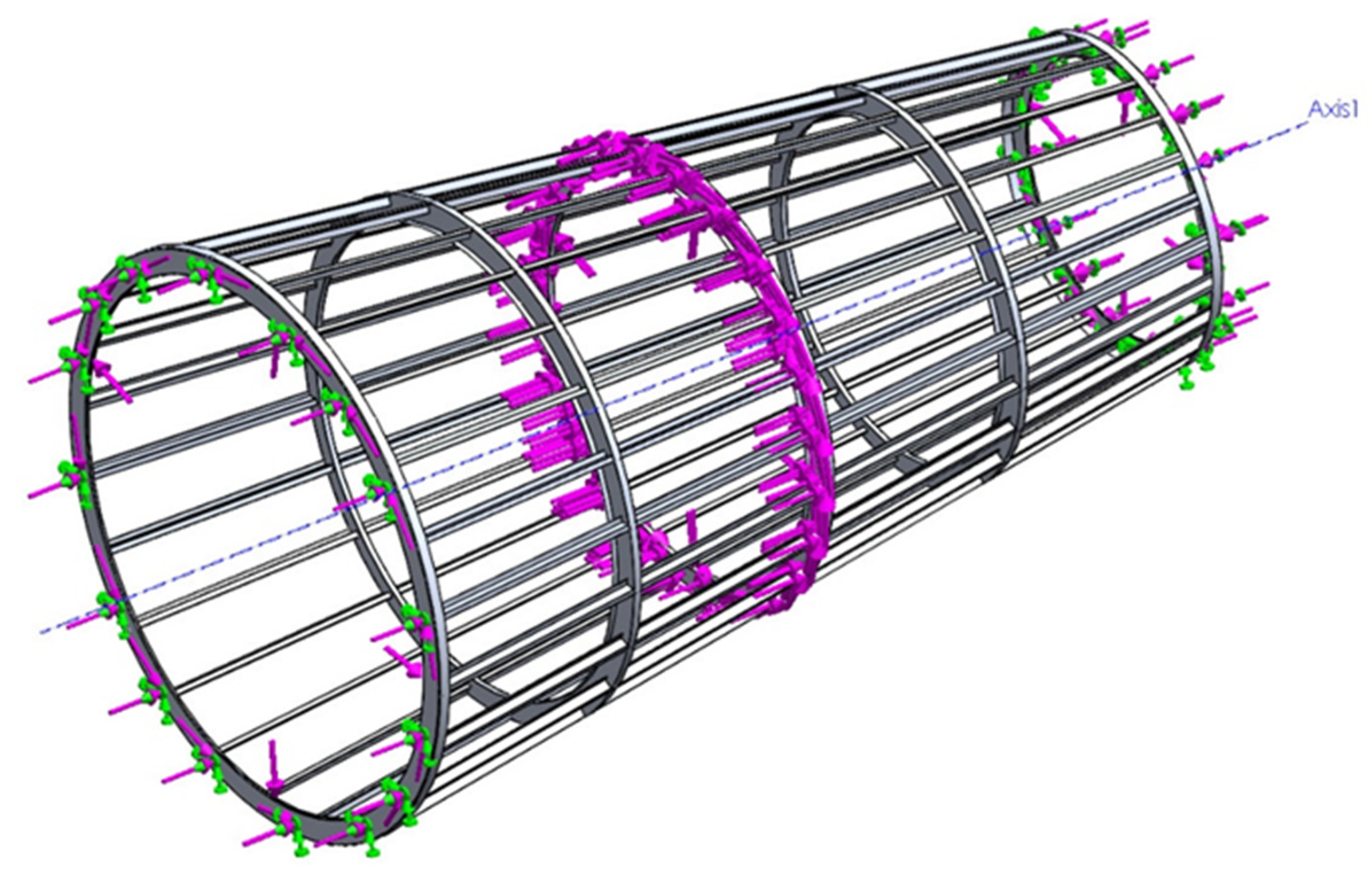
After the static simulation, a fatigue test is created from the static test data. The loading defined is a constant amplitude event that is fully reversed (LR = −1) over 1000 cycles. The SN curve for the specified material is then assigned to the model, and the simulation is then performed. It took about 2 min to complete as most of the data was already calculated from the static simulation (Figure 1).

Figure 1.
Applied loading orientations on the model in solidworks. The forces and torques are indicated by the purple-colored arrows. The arrows colored green indicate fixed geometry.
3. Results and Discussion
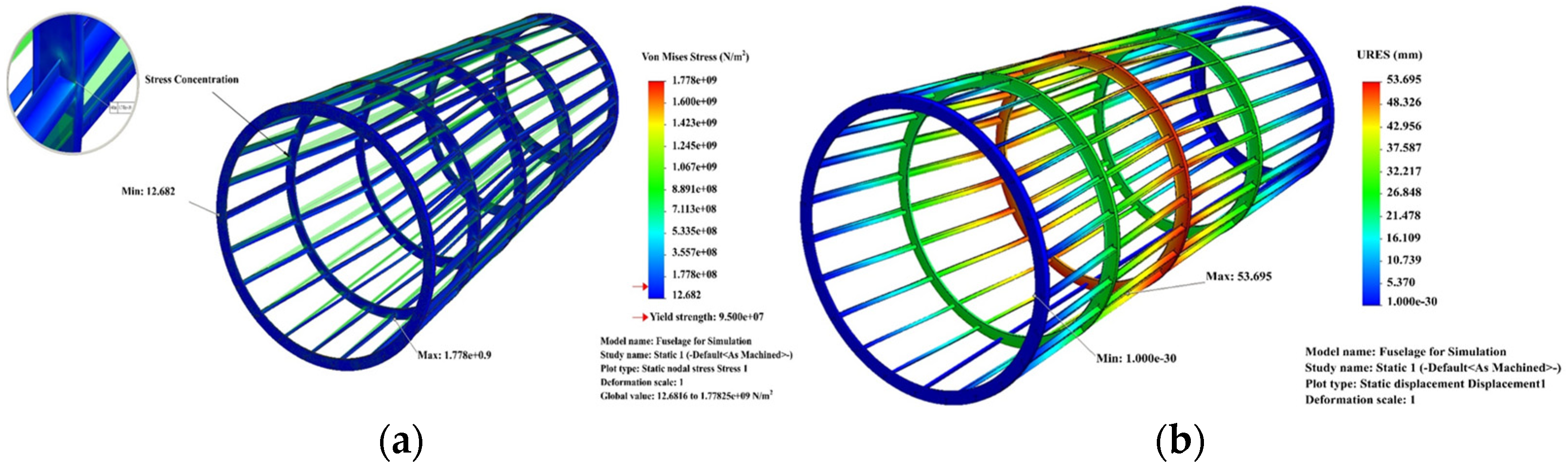
From the values obtained from static loading, it can be said that the stress is maximum at the joints, and this is minimized by using rivets for the joints. For the displacement, the reinforcement from the rivets and the skin of the fuselage would be able to reduce the displacement to a minimum (Figure 2). In the case of strain, the values are manageable.

Figure 2.
(a) Stress result. (b) Relative displacement.
Corresponding to the damage, the maximum life cycle occurs where the damage is minimum and has the value of 10 million cycles (Figure 3). The minimum life cycle occurs at the rear joints where the damage is maximum and has a value of 50,000 cycles (Figure 3).
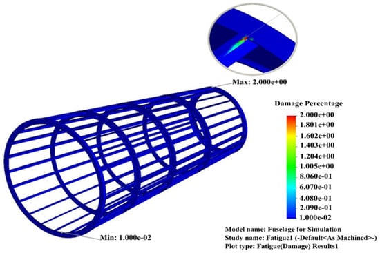
Figure 3.
Damage percentage.
Taking a safer approach, linear fracture mechanics is used to estimate the life cycle. Assuming there is a crack present with an initial length of 0.2 mm at the stress concentration sites, the initial cracks are likely to be very small, less than a millimeter, and, therefore, difficult to identify on inspection [7,8].
Therefore, the number of cycles to failure with crack growth or crack propagation is about half the value of the minimum number of cycles obtained by simulation, which is 50,000 cycles. Hence, if the aircraft makes 0.5 cycles/h, then the recommended total flight hours for the aircraft would be 53,838 flight hours [7,8,9]. After these flight hours, the whole fuselage would be taken out for repair and a new fuselage should be installed. Inspection should be carried out after every quarter of the total flight hours.
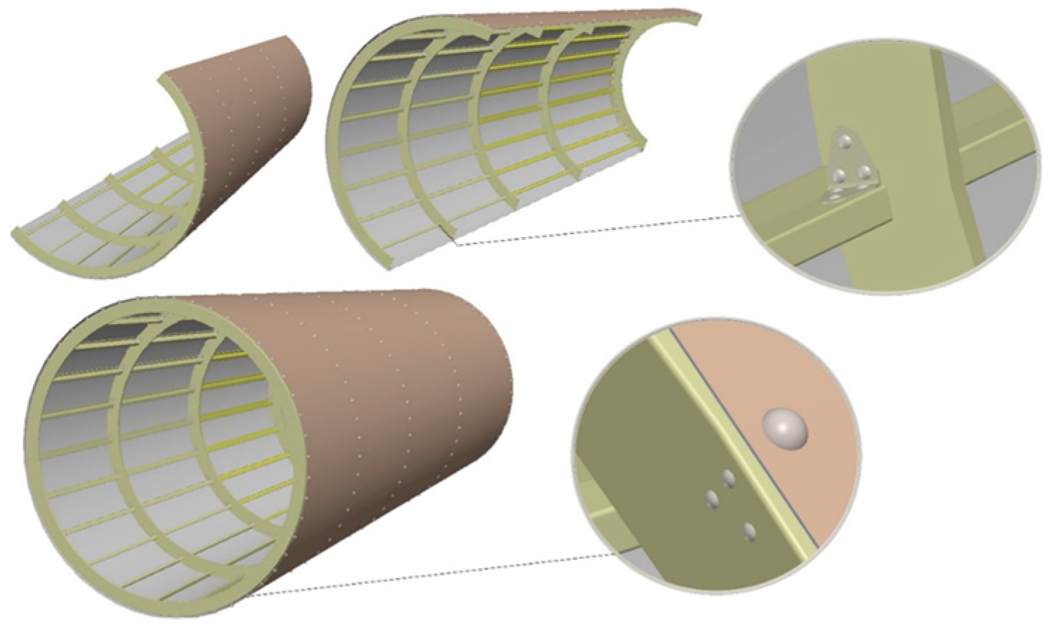
The joints between the stringers and the frames are riveted with titanium rivets and reinforced with brackets (Figure 4). The skin thickness should be equal to or greater than 1.5 times the countersink rivet depth in critical fatigue areas to avoid knife edge effects (Figure 4).
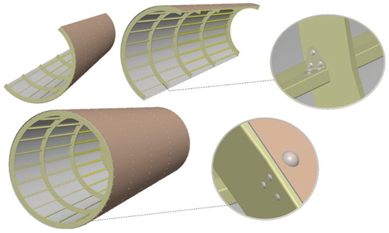
Figure 4.
Rear fuselage with riveted joints and skin attached.
4. Conclusions
Fatigue is a common problem in every mechanical structure and machine element, and fatigue failure occurs without warning. Hence, in order to be one step ahead of the failure, engineers must be able to predict fatigue failure so that machine parts and structures are taken out and replaced just in time to avoid any catastrophic failure. This report presents a prediction of the fatigue life of the fuselage using solidworks simulation as well as an analytical prediction technique using linear fracture mechanics. It is always a good design practice to use worst-case scenarios to predict failures to be on the safe side rather than to be precise. This is because the machine or part would operate at less severe operating conditions than the predicted scenario.
Author Contributions
Conceptualization, M.M. and A.M.; methodology, B.B.V.L.D.; validation, M.M. and J.W.; formal analysis, B.B.V.L.D.; investigation, J.W.; resources, M.M.; data curation, M.M.; writing—original draft preparation, A.M.; writing—review and editing, M.M. and A.M.; visualization, A.M.; supervision, A.M.; project administration, A.M.; funding acquisition. All authors have read and agreed to the published version of the manuscript.
Funding
This research received no external funding.
Institutional Review Board Statement
Not applicable.
Informed Consent Statement
Not applicable.
Data Availability Statement
All data are provided in the article.
Conflicts of Interest
The authors declare no conflict of interest.
References
- Russell, J.; Hugh, W. Durability and damage tolerance analysis methods for lightweight aircraft structures: Review and prospects. Int. J. Lightweight Mater. Manuf. 2022, 5, 224–250. [Google Scholar] [CrossRef]
- Abbishek, R.; Ravi Kumar, B.; Sankara Subramanian, H. Fatigue Analysis and Design Optimization of Aircraft’s Central Fuselage. IOP Conf. Ser. Mater. Sci. Eng. 2017, 225, 012031. [Google Scholar] [CrossRef]
- Mogili, U.R.; Deepak, B.B.V.L.; Parhi, D.R.; Mohamed, A. Droplet Distribution Effected by Multi-Rotor Flight Parameters. In Recent Trends in Product Design and Intelligent Manufacturing Systems; Deepak, B., Bahubalendruni, M.R., Parhi, D., Biswal, B.B., Eds.; Spinger: Singapore, 2023; pp. 231–240. [Google Scholar] [CrossRef]
- Karthick, B.; Balaji, S.; Maniiarasan, P. Structural Analysis of Fuselage with Lattice Structure. Int. J. Eng. Res. Technol. 2013, 2, 1909–1913. [Google Scholar]
- Chetan, B.S.; Narayana Swamy, G.; Girish, K.E. Fatigue Life Estimation of Rear Fuselage Structure of An Aircraft. Int. J. Res. Eng. Technol. 2015, 4, 347–354. [Google Scholar] [CrossRef]
- Leski, A. Improving the Accuracy of Fatigue Damage Calculations for Archived Data. Fatigue Aircr. Struct. 2020, 2019, 113–120. [Google Scholar] [CrossRef]
- Mohamed, A.; El-Madhoun, Y.; Bassim, M.N. The Effect of Tempering on Low Cycle Fatigue Behavior of Al2024. J. Mater. Process. Technol. 2005, 162, 362–366. [Google Scholar] [CrossRef]
- Gomes, G.; Oliveira, T.; Evangelista, F., Jr. A Probabilistic Approach in Fuselage Damage Analysis via Boundary Element Method. In Advances in Fatigue and Fracture Testing and Modelling; Abdallah, Z., Nada, A., Eds.; IntechOpen: London, UK, 2022. [Google Scholar] [CrossRef]
- Zhang, Y.; Wang, B.; Ning, Y.; Xue, H.; Lei, X. Study on Health Monitoring and Fatigue Life Prediction of Aircraft Structures. Materials 2022, 15, 8606. [Google Scholar] [CrossRef]

Disclaimer/Publisher’s Note: The statements, opinions and data contained in all publications are solely those of the individual author(s) and contributor(s) and not of MDPI and/or the editor(s). MDPI and/or the editor(s) disclaim responsibility for any injury to people or property resulting from any ideas, methods, instructions or products referred to in the content. |
© 2024 by the authors. Licensee MDPI, Basel, Switzerland. This article is an open access article distributed under the terms and conditions of the Creative Commons Attribution (CC BY) license (https://creativecommons.org/licenses/by/4.0/).