Abstract
Due to the increased development of urban areas and climate change, water resource management is gaining more attention. Among the most important aspects under scrutiny is improving the reliability of water resources. In this paper, the focus is on the dynamic modelling of a well field in EPANET. By dynamic modelling, we mean that the numerical model can adjust the water levels in the wells with respect to the extracted flow rate, according to the results of the hydrogeological study of the area. The operation of a well field must sometimes be realized at partial loads. In this latter case, all the duty points of the pumps in operation change and the flow rates may exceed the maximum allowed values, leading to the rapid clogging of the wells. The model and results obtained for different operating scenarios will be presented in the paper.
1. Introduction
Due to the increased development of urban areas and climate change, water resource management (especially drinkable water resources) is gaining more attention nowadays from the water companies. Among the most important aspects under scrutiny are maintaining or improving the quality of the resource, improving the reliability of the resource and of the supply system and, last but not least, reducing the energy needed to transport the resource where it is needed. In this respect, the water company of Bucharest, in order to improve the reliability of the resource, is considering using small well fields for the emergency supply of the city. Of course, these small well fields are not meant as a replacement for the existing water sources in case of depletion but as an addition that will be used in the case of droughts or failures in the operation of the water distribution system. The focus of the paper is on the dynamic modelling of a new well field in EPANET. In this context, by dynamic modelling, we mean that the numerical model can adjust the water levels in the wells with respect to the extracted flow rate, according to the hydrogeological study of the area. Although such a problem, which is a quasi-steady one, has well-known solutions for a single well, it becomes more complex for a well field where all the extraction pipes and pumps are linked together in a small supply system. Moreover, the operation of a well field must sometimes be realized at partial loads [1], either due to low water consumption, or due to revisions or damaged equipment replacement, meaning that some of the pumps are turned off in the system. In this latter case, at least intuitively, it is obvious that all the duty points of the pumps in operation migrate to the right at higher flow rates that can exceed the optimal flow rate, leading to the rapid clogging of the wells. Setting up such a model in EPANET 2.2 will be discussed, and the results for different operating scenarios will be presented.
2. Materials and Methods
EPANET is free software specialized in modelling water distribution systems. It works with predefined objects (such as nodes, water sources, tanks, pumps, pipes, and valves) that can be used in simulations. Most of the other types of fittings, and measuring and control devices, which might be present in a water distribution system, can be simulated either by means of certain properties of different objects (e.g., one of the pipe properties can be set as well as “check valve”, which means that water through that pipe is constrained to flow in one direction only, namely from the initial node to the final node; one of the properties of the nodes is the “emitter coefficient”, which can be used to replicate the existence of different types of sprinklers or orifices existing in the network), or found in the category of valves (e.g., pressure-reducing or pressure-sustaining valves). There are no predefined objects such as turbines or wells, but the manual mentions that such objects can be simulated using the “general purpose valve” where the user can specify a curve representing the variation of the head loss with flow. Thus, for the case of wells, a curve can be used to represent the variation of the difference between the hydrostatic and hydrodynamic levels depending on the flow rate extracted from the well [2,3,4], a curve that can be obtained from a hydrogeological model.
This procedure was used in this case of all 8 wells in the field. The results of the hydrogeological study in terms of levels are presented in Table 1, for the maximum flow rate that will be extracted from the wells (i.e., 6.5 L/s). Results are also provided for a flow rate considered to be the minimum flow rate that will be extracted from the wells (i.e., 2 L/s). The maximum flow rate that will be extracted from the wells is a bit smaller than the maximum flow rate accepted to avoid clogging (i.e., 6.8 L/s) which resulted during the pumping tests performed in situ for well F1.

Table 1.
Wells water levels (hydrostatic level ZHs and hydrodynamic level ZHd) according to the hydrogeological study for the maximum flow rate (Q) extracted; the wells are labelled as F1÷F8.
Each well is considered a cylindrical water tank (the diameter of the tank being considered equal to the diameter of the well, i.e., 20 cm), with a variable level (the initial level of water in the tank being considered the hydrostatic level). Since the hydrostatic level differences between the wells are very small (maximum difference of 10 cm), we considered the hydrostatic level constant for the entire catchment, located at an elevation of 40.75 m. The wells are fed from an infinite water source with a constant hydrostatic level of 40.75 m through some general-purpose valves for which the level difference curves were introduced depending on the extracted flow resulting from the hydrogeological study.
The well field is situated in an area that is managed by the water company. It is the location of some of the water storage tanks of Bucharest and of one of the major pumping stations feeding the water distribution network. A sketch of the premises is presented in Figure 1. Pipes of the well field are coloured depending on the diameter and nodes are coloured in function of the elevation.
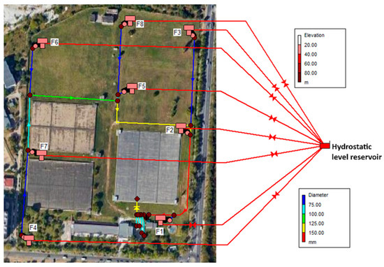
Figure 1.
The sketch of the well field—the wells are labelled from F1 to F8.
The water extracted from the wells will be pumped into the existing 55,000 m3 reservoir on the premises. The water will be disinfected with volumetrically dosed sodium hypochlorite solution. Four loading points equipped with hydrant type connections will be set up on the aqueduct. Extended time simulations were used to allow the levels in the wells to adjust. The total duration of each simulation was one hour with a hydraulic and quality time step of 5 s.
3. Results and Discussion
The simulations were performed for both maximum and minimum flow rates that will be extracted from the wells. For the simulation performed for the maximum flow rate, although the starting hypothesis was a constant flow rate for all wells, results show that each well extracts a different flow rate (Figure 2) due to the geometrical configuration of the system, some of them exceeding the maximum flow rate accepted to avoid clogging. All tanks reached a constant hydrodynamic level after less than 5 min.
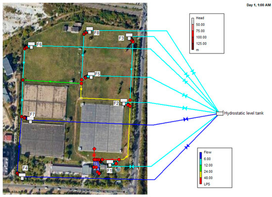
Figure 2.
Results for the maximum flow rate that will be extracted from the wells (submersible pumps speed is 1) after one hour of simulation (the wells are labelled from F1 to F8).
As all the submersible pumps are equipped with variable frequency drives, in the case where the maximum flow rate accepted to avoid clogging was exceeded, the speed of the pump was reduced in order to keep the flow rate as close as possible to the prescribed one from the hydrogeological study.
For the minimum flow rate, the speeds of some pumps were adjusted in order to keep the flow rate as close as possible to the prescribed one from the hydrogeological study (i.e., 2 L/s) for all wells. The obtained speed settings were transmitted to the water company as results of study.
4. Conclusions
The EPANET numerical model built for the well field has proven useful in maintaining a balance between the extracted flow rates from each well. As the well field will be developed and equipped with measuring and control devices, the numerical model will represent the first step towards a digital twin of the system. Coupling it to the hydrogeological numerical model will be a novel approach ensuring the optimal control of the system from both the extracted flow rate point of view, as well as from the point of view of the reduction in energy used for pumping.
Author Contributions
Conceptualization, A.-M.G.; methodology, A.-M.G. and S.-C.G.; software, S.-C.G. and A.-M.G.; validation, Ș.-D.G., S.-C.G. and A.-M.G.; formal analysis, S.-C.G. and A.-M.G.; investigation, Ș.-D.G., I.I. and A.-M.G.; resources, Ș.-D.G. and I.I.; data curation, Ș.-D.G.; writing—original draft preparation, S.-C.G. and A.-M.G.; writing—review and editing, S.-C.G. and A.-M.G.; visualization, S.-C.G.; supervision, A.-M.G. All authors have read and agreed to the published version of the manuscript.
Funding
This research received no external funding.
Institutional Review Board Statement
Not applicable.
Informed Consent Statement
Not applicable.
Data Availability Statement
The data presented in this study are available upon request from the corresponding author.
Acknowledgments
The authors gratefully acknowledge Apa Nova București S.A. for providing data regarding the studied well field.
Conflicts of Interest
The authors declare no conflicts of interest.
References
- Anton, A.; Georgescu, A.M.; Perju, S.; Georgescu, S.C.; Cosoiu, C.I.; Hasegan, L. Simulation of the partial load operation of an urban groundwater well field. Procedia Eng. 2015, 119, 1147–1152. [Google Scholar] [CrossRef][Green Version]
- Iancu, I.; Dimache, A.N.; Georgescu, S.C.; Georgescu, A.M. EPANET modeling of an urban groundwater field. E3S Web Conf. 2019, 85, 06003. [Google Scholar] [CrossRef]
- Georgescu, A.M.; Georgescu, S.C.; Berardi, L.; Laucelli, D.B.; Giustolisi, O. Modelling an urban groundwater well field with WDNetXL/WDNetGIS. In Proceedings of the 2019 International Conference on Energy and Environment (CIEM), Timisoara, Romania, 17–18 October 2019; IEEE: Piscataway, NJ, USA, 2019; pp. 254–258. [Google Scholar] [CrossRef]
- Berardi, L.; Laucelli, D.B.; Georgescu, S.C.; Georgescu, A.M.; Simone, A.; Ciliberti, F.G.; Giustolisi, O. Modellazione del pompaggio da pozzi mediante il sistema WDNetXL/WDNetGIS. L’Acqua 2019, 5, 51–53. [Google Scholar]


Disclaimer/Publisher’s Note: The statements, opinions and data contained in all publications are solely those of the individual author(s) and contributor(s) and not of MDPI and/or the editor(s). MDPI and/or the editor(s) disclaim responsibility for any injury to people or property resulting from any ideas, methods, instructions or products referred to in the content. |
© 2024 by the authors. Licensee MDPI, Basel, Switzerland. This article is an open access article distributed under the terms and conditions of the Creative Commons Attribution (CC BY) license (https://creativecommons.org/licenses/by/4.0/).