Proceeding Paper

Optimized Design of Dead-End Spoiler Using PIV †

1
School of Environment, Harbin Institute of Technology, Harbin 150090, China
2
School of Engineering and the Built Environment, Birmingham City University, Birmingham B4 7XG, UK
3
School of Municipal and Environmental Engineering, Heilongjiang Institute of Construction Technology, Harbin 150025, China
4
Engineering Department, Harbin Corner Science & Technology Inc., Harbin 150028, China
*
Author to whom correspondence should be addressed.
Presented at the 3rd International Joint Conference on Water Distribution Systems Analysis & Computing and Control for the Water Industry (WDSA/CCWI 2024), Ferrara, Italy, 1–4 July 2024.
Eng. Proc. 2024, 69(1), 183; https://doi.org/10.3390/engproc2024069183
Published: 9 October 2024

Abstract

:
In this study, the efficacy of varying spoiler design parameters on regulating dead-end contaminant diffusion was investigated using particle image velocimetry (PIV) technology. The optimal spoiler design parameters were identified under low Reynolds number turbulence, including variables such as tilt angle, height, width, and installation position. The findings of this study present a novel approach for improving water quality in WDNs by installing spoilers in dead-ends while offering valuable insights and providing guidance for the design and optimization of these spoilers.

1. Introduction

Contaminants in dead-end branches can easily diffuse into the main pipes with the flow and exacerbate water quality contamination in water distribution networks (WDNs) through secondary pressurization, affecting the safety of consumer water usage. Currently, methods such as pipeline cleaning are commonly used to reduce contaminants in dead-ends, which have low efficiency, high energy consumption, high cost, and long water outage times [1,2]. Therefore, it is crucial to find new effective measures to prevent contaminant entry into the main pipes. This study proposes the installation of spoilers in dead-ends, aiming to explore the control effects of different specifications of spoilers on contaminant diffusion in dead-end branches under low Reynolds number turbulence using particle image velocimetry (PIV) technology, to optimize the design parameters of the spoilers.

2. Methods

2.1. PIV Setup

The PIV setup mainly consisted of four parts: a light source system, a flow field to be measured, an image acquisition system, and an image processing system. The light source used a continuous laser with a wavelength of 532 nm and a rated power of 10 W. The seeding particles were opaque white polyamide resin particles with an average diameter of 50 μm, a refractive index of 1.582, and a density of 1.03 g/cc. Image acquisition was performed using an ISP504 high-speed camera with an exposure time of 1 microsecond and a resolution of 2320 × 1720 pixels, with focal lengths of 50 mm and 105 mm.

2.2. Experimental Platform

To conduct PIV observations of the spoiler’s control over contaminant diffusion in dead-ends, an experimental platform was constructed. The platform occupied 60 m² and was arranged as a circular water supply loop, consisting of a water tank, pipes, a pump, a transparent flow field for seeding particles, a variable frequency controller, valves, an electromagnetic flowmeter, a potentiometric remote transmission pressure gauge, and other main components and accessories.

2.3. Experimental Conditions

The primary function of the flow disruptors in this study was to create cavity structures in the turbulence, causing the incoming flow shear layer to cross the cavity without directly impacting the fluid inside the dead-end branch, thereby weakening the mixing characteristics between the dead-end branch and the main pipe and reducing the diffusion of pollutants from the dead-end branch into the main pipe. The design parameters for the various spoilers used in the experiments are shown in Table 1. Figure 1 illustrates a schematic of the spoiler.
The incoming flow velocity in the main pipe was designed to be 1.00 m/s, with a Reynolds number of 85,785 to maintain a degree of local uniform flow in the incoming main pipe. In all experiments, the concentration of seeding particles was 1 g/m³, and the direction of the incoming flow in the main pipe was forward.

3. Results and Discussion
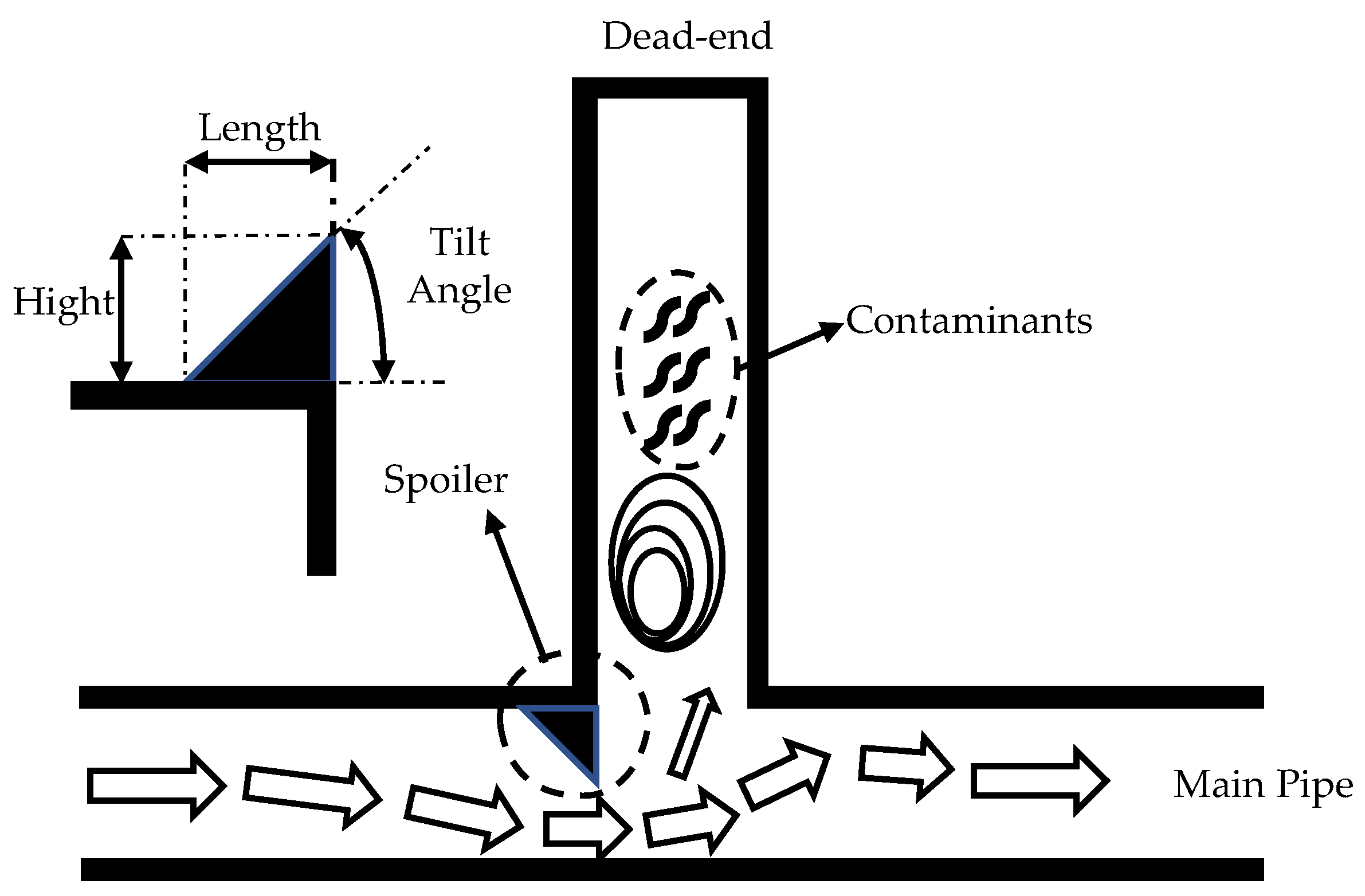
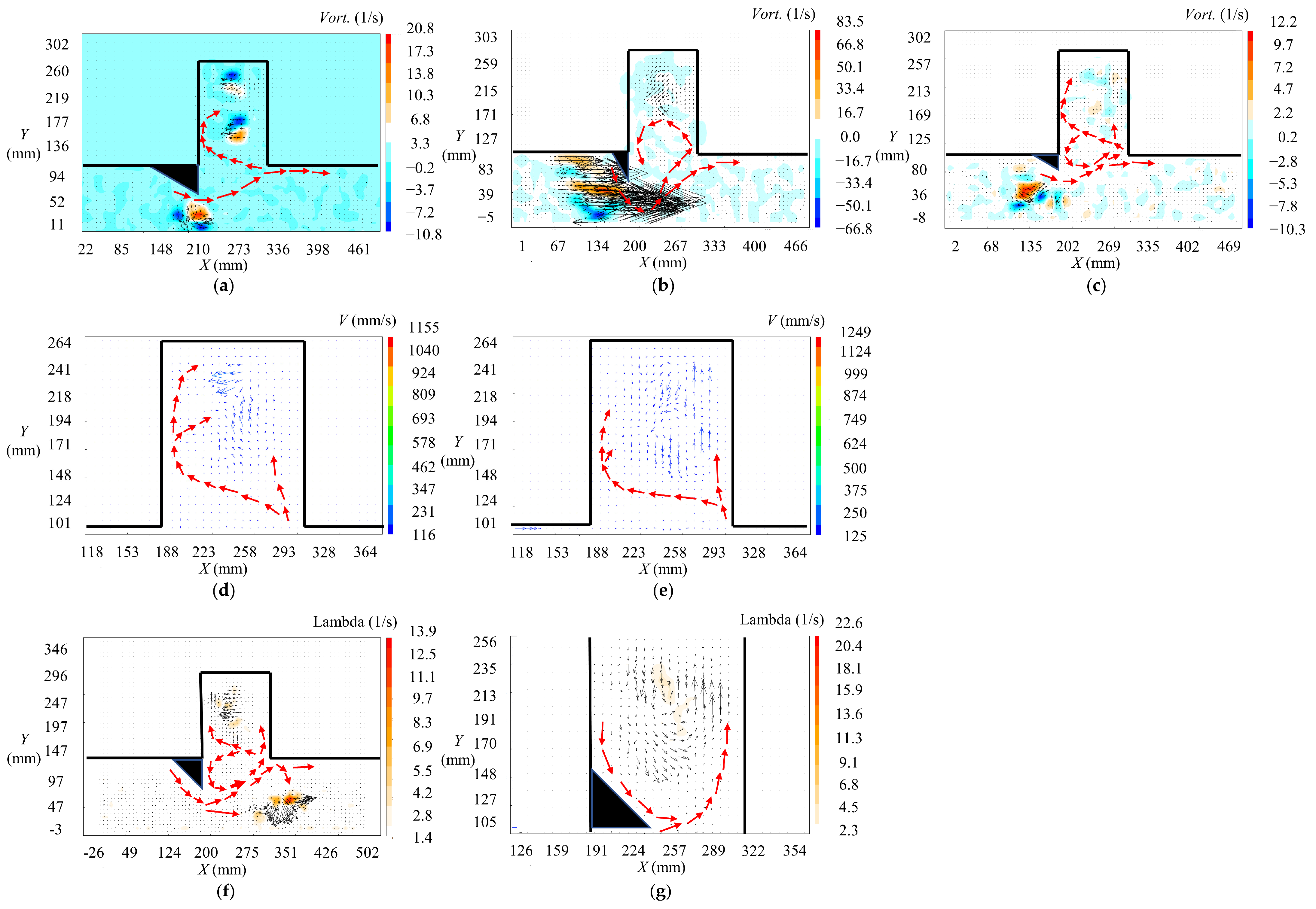
3.1. Tilt Angle

As shown in Figure 2a,b, when the tilt angle of the spoiler was 30°, a more pronounced right-to-left lateral flow field appeared at the bottom of the dead-end branch. The fluid entering the dead-end branch tended to move laterally, hindering the diffusion of contaminants from the dead-end branch into the main pipe. With a tilt angle of 60°, the fluid entering the dead-end branch tended to move longitudinally, generating vortices at the bottom of the dead-end branch, which could easily carry contaminants from the dead-end branch into the main pipe. It can be inferred that a spoiler with a tilt angle of 30° has a better effect on controlling the diffusion of contaminants within dead-end branches.

3.2. Height

As shown in Figure 2a,c, with a height of 2.00 cm, the flow from the main pipe entering the dead-end branch only formed a single clockwise vortex inside the dead-end branch. However, with a height of 1.15 cm, the kinetic energy of the flow entering the dead-end branch was stronger due to less obstruction by the spoiler, making it easier to form multiple vortices, increasing the mixing intensity, and exacerbating the diffusion of contaminants within the dead-end branch. It is evident that, with other design parameters being equal, a spoiler with a greater height has a better control effect.

3.3. Width

As shown in Figure 2d,e, when spoilers of different widths were installed, the internal flow field of the dead-end branch was similar, showing a clockwise rotational flow. Comparing the two, it was found that with a larger width of the spoiler, the trend of the clockwise rotating vortex was more pronounced, suggesting a better control effect on contaminants. Nevertheless, compared to length and height, the width of the spoiler had a less significant impact on the fluid-flow state within the dead-end branch.

3.4. Installation Position

As shown in Figure 2f,g, when the spoiler was installed at the front edge of the main pipe, the flow from the main pipe moved up along the left and right walls of the dead-end branch, and only a counterclockwise rotating vortex formed at the entrance of the branch, with the contaminants within the branch being almost undisturbed by the flow from the main pipe. When the spoiler was installed at the front edge of the branch, the flow from the main pipe moved up along the right wall of the dead-end branch, and due to the obstruction of the spoiler, it reflected off the left wall, forming a counterclockwise rotating vortex inside. The cross-sectional area of the branch was reduced, increasing the kinetic energy of the fluid entering the branch, exacerbating the release of contaminants within the branch. Therefore, installing the spoiler at the front edge of the main pipe had a better effect on controlling the diffusion of contaminants within the dead-end branch.

Author Contributions

Conceptualization, J.G. and K.L.; methodology, W.W.; software, S.Q.; validation, H.C., W.Q. and J.H.; formal analysis, J.Z. and Y.D. All authors have read and agreed to the published version of the manuscript.

Funding

This research was funded by the National Key Research and Development Program of China, grant number 2022YFC3203800; the National Natural Science Foundation of China, grant number 51978203; the Unveiling Scientific Research Program, grant number CE602022000203; the Key Research and Development Program of Heilongjiang Province of China, grant number 2022ZX01A06.

Institutional Review Board Statement

Not applicable for studies not involving humans or animals.

Informed Consent Statement

Informed consent was obtained from all subjects involved in the study.

Data Availability Statement

For access, contact the corresponding author.

Conflicts of Interest

Junjun He was employed by the company Harbin Corner Science & Technology Inc. The remaining authors declare that the research was conducted in the absence of any commercial or financial relationships that could be construed as a potential conflict of interest. The authors declare no conflicts of interest.

References

  1. Ellison, D. Investigation of Pipe Cleaning Methods, 1st ed.; AWWA Research Foundation and American Water Works Association: Denver, CO, USA, 2003; pp. 35–36. [Google Scholar]
  2. Vitanage, D.; Pamminger, F.; Vourtsanis, T. Safe Piped Water: Managing Microbial Water Quality in Piped Distribution Systems, 1st ed.; World Health Organization and IWA Publishing: London, UK, 2004; pp. 91–94. [Google Scholar]
Figure 1. Schematic of the spoilers.
Engproc 69 00183 g001
Figure 2. Observation of the flow field at the dead-end with different parameters of the spoiler using PIV: (a) with spoiler No. 2; (b) with spoiler No. 3; (c) with spoiler No. 4; (d) with spoiler No. 5; (e) with spoiler No. 6; (f) with spoiler No. 1 at the front edge of the main pipe; (g) with spoiler No. 1 at the entrance of the dead-end branch.
Engproc 69 00183 g002
Table 1. Design parameters for the various spoilers used in the experiments.
No.Applicable Pipe DiameterTilt AngleHeight (cm)Width (cm)
1DN10045°2.008.00
2DN10030°2.008.00
3DN10060°2.008.00
4DN10030°1.158.00
5DN10045°2.004.00
6DN10045°2.002.00
Disclaimer/Publisher’s Note: The statements, opinions and data contained in all publications are solely those of the individual author(s) and contributor(s) and not of MDPI and/or the editor(s). MDPI and/or the editor(s) disclaim responsibility for any injury to people or property resulting from any ideas, methods, instructions or products referred to in the content.

