Proceeding Paper

Communication System Comparison of IoT Applications Using Custom-Designed Antennas: A Basic Experimental Study †

by
Marco Vinueza Bustamante
*,
Jordan Guillén Arteaga
,
Carlos Yépez Vera
,
Aldrin Reyes Narváez
and
Hernan Barba Molina
Departamento de Electrónica, Telecomunicaciones y Redes de Información, Escuela Politécnica Nacional, Quito 170143, Ecuador
*
Author to whom correspondence should be addressed.
Presented at the XXXII Conference on Electrical and Electronic Engineering, Quito, Ecuador, 12–15 November 2024.
Eng. Proc. 2024, 77(1), 16; https://doi.org/10.3390/engproc2024077016
Published: 4 November 2024
(This article belongs to the Proceedings of The XXXII Conference on Electrical and Electronic Engineering)

Abstract

:
A comparative study of the performance of a communication system for IoT applications is presented. The experiment is based on the bit error rate, which is obtained by varying the distance between two transceiver modules, each attached to a microcontroller Arduino Uno. Four scenarios are considered for our experimentation. Each scenario is mainly characterized by interchanging radiator elements which are attached to the transceiver modules. For this, two antennas are designed and implemented: a modified shape-optimized Landstorfer Yagi-Uda antenna and a printed turnstile antenna. The measurements show good agreement, with simulations having gain values of about 9 dBi and 3 dBi for the quasi Yagi-Uda structure and the turnstile antenna, respectively. System performance tests are conducted to compare the performance of the commercial solution at various distances to custom-designed antennas. These tests aim to evaluate the improvement achieved using a new set of antennas. The key to this solution is the use of a high-directivity antenna for data transmission and a circular polarized omnidirectional antenna for reception, which shows an improvement of around 60% in terms of the bit error rate during data transmission compared to the pair of commercial antennas included in the RF module.

1. Introduction

Wireless communication allows a link between different nodes through electromagnetic waves, microwaves, or light signals [1]. Furthermore, this technique is highly adaptable due to the use of unguided channels, which enable mobility and facilitate communication across challenging geographic areas. However, these channels are subject to various perturbations, including distance, interference, and atmospheric conditions, which could degrade signal quality.
Telecommunication companies design and implement equipment for general-purpose applications, utilizing standardized antennas that enable communication between devices. While these generic solutions provide basic connectivity, they are significantly affected by channel perturbations, as they are not optimized for specific use cases. Consequently, these generic systems struggle to maintain long-distance communication with a low bit error rate (BER) with the same power as custom-designed equipment. Specially, in IoT communication systems, wireless communications have been utilized for location tracking, data logging, and efficient transportation, which have significantly benefited from the use of custom-designed equipment [2].
Many approaches to the evaluation of the performance of wireless communication systems in real-world scenarios have been carried out as part of field tests. Firstly, an IoT network has been tested in terms of its Received Signal Strength Indicator (RSSI) and Packet Error Rate (PER) inside a university campus [3]. This study led the authors to propose an IoT network deployment for this area. Next, an experimental evaluation of an IoT network using LoRa for campus deployment is reported in [4], which focuses on the link quality, quantified through various parameters in different scenarios. Furthermore, over-the-air (OTA) performance evaluations of IoT wireless devices are also made, providing solutions to ensure efficient approaches [5].
In any IoT network evaluation, the hardware involved plays a crucial role. Commercial RF modules used as part of sensor nodes are commonly provided with conventional dipole antennas designed to radiate into free space at their operation frequency. This fact is related mainly because of its ease of use and the bandwidth used (up to 160 MHz), which is sufficient for most wireless applications [6]. In this context, many studies have been carried out utilizing merely the provided commercial dipole. Transmission methods have been analyzed for the IoT in both short- and long-range networks, encompassing technologies such as ESP-NOW, nRF24L01 modules, and local Wi-Fi access points [7]. In [8], the development of a wireless communication system using the nRF24L01 transceiver module and an Arduino Uno is described. The system operates at a frequency of 2.4 GHz, supports data transmission rates between 250 kbps and 2 Mbps, and has a communication range of approximately 80–100 m. The design allows for both transmitting and receiving data, using a compact setup that integrates the NRF24L01 with an Arduino Uno microcontroller.
Regarding the antennas attached to the transceiver modules, a microstrip patch antenna has been designed for IoT devices operating within the 868 MHz frequency band [9]. In order to obtain ultra-wide bandwidth, a U-shaped UWB antenna has been designed and analyzed for IoT applications [10].
In this paper, a performance comparison of IoT applications based on a basic experimental study at 2.4 GHz is proposed, which changes between commercial dipoles and two custom-designed antennas. Section 2 provides a description of the system used for the tests, the antenna structures, and the experimental approach. The results of the antenna design and the performance of the proposed system are presented in Section 3. Conclusions are depicted in Section 4.

2. Methodology

This section describes the methodology used to achieve this communication system comparison.

2.1. Equipment System Description

Figure 1 shows the proposed experimental setup of the IoT system used to evaluate the performance of a long-distance IoT communication system operating at 2.4 GHz. The system employs two RF modules, namely an NRF24L01 model; two computers; two microcrontrollers (Arduino Uno); and the custom-designed antennas under test. The system comprises two primary units—the transmission unit (TxU) and the reception unit (RxU)—each configured with specific components to optimize overall performance.

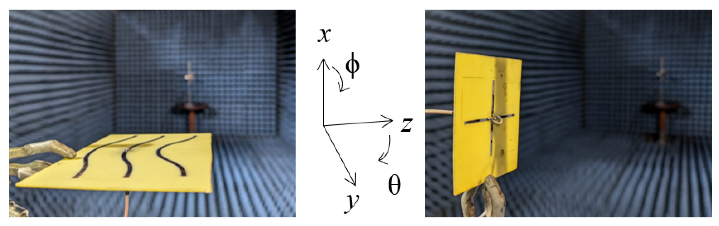
2.2. Antennas Under Test

Figure 2 shows the structures of the antennas, which are attached to the RF modules in different scenarios to carry out the IoT performance evaluation. A modified shape-optimized Landstorfer Yagi-Uda antenna (LaYUA) and a turnstile antenna composed of two printed dipole radiators (TuSA) are presented as custom-designed radiators for the experiment. Additionally, the commercial dipole antenna included in the RF modules is utilized for in this experimentation.
The LaYUA radiator is a scaled version, at 2.4 GHz, of the antenna reported in [11] and serves as the radiator for transmission. The analysis of a turnstile antenna is detailed in [12,13], with the key difference being that the 90°-phased dipole is achieved through a coaxial line. Due to its low gain, this antenna operates at the reception side. Lastly, the commercial dipole corresponds to a 2.4 GHz antenna with an RP-SMA connector that is to be attached to the RF module.

2.3. Experimental Approach

According to Figure 1, the units TxU and RxU are linked through a wireless channel. On both sides, a computer is connected to a microcontroller (Arduino Uno), which in turn interfaces with an RF module (NRF24L01). These RF modules operate at 2.4 GHz and are equipped with both a low-noise amplifier and a power amplifier to enhance their transmission and reception capabilities. This RF module employs the SPI (Serial Peripheral Interface) for communication between the module and the microcontroller. Thus, the NRF24L01 implements its proprietary wireless communication protocol, operating in the 2.4 GHz ISM band. The latter includes features such as addressing, error control, and the capability to handle multiple channels and addresses, enabling, in this way, robust wireless data transmission and reception [14].
In order to ensure the relevance of the measurements and minimize interference, the TxU and RxU were strategically placed at distances varying from 10 m to 100 m in an open-field environment, specifically chosen to reduce obstructions and minimize external interference from buildings, vegetation, or other sources of signal reflection and attenuation. The tests were conducted under clear weather conditions, with environmental factors of a 18.7 °C temperature and 65.8% humidity. Additionally, a key feature taken into account in this experiment is the tilt angle of the linear polarized antennas (LaYUA and commercial dipole) to achieve polarization matching. This adjustment is essential for accurately evaluating the system’s performance metrics. The system is tested under a transmit power level of 0 dBm and a data rate of 2 Mbps to evaluate the bit error rate (BER) characteristic across different scenarios, including urban fading profiles, which will be discussed in the following sections. A low BER implies high-quality communication, which is essential for reliability in IoT applications. Furthermore, it is critical for assessing system efficiency, as a high error rate requires retransmissions, thereby increasing latency and energy consumption in battery-dependent IoT devices.
A key component of this setup is the use of different antenna structures for the evaluation. Four different scenarios are examined to analyze the impact of these configurations on wireless communication performance:
Scenario 1
Commercial dipole antennas: This is the baseline scenario. Both the TxU and RxU are attached with standard commercial dipole antennas.
Scenario 2
LaYUA and commercial dipole: This scenario includes the LaYUA, attached to the TxU, and the commercial dipole antenna, attached to the RxU.
Scenario 3
Commercial dipole and TuSA: This scenario utilizes the commercial dipole antenna, attached to the TxU, and the TuSA, attached to the RxU.
Scenario 4
LaYUA and TuSA: This scenario uses the LaYUA, attached to the TxU, and the TuSA, attached to the RxU.

3. Results

This section presents the results obtained in each phase of this experimental study.

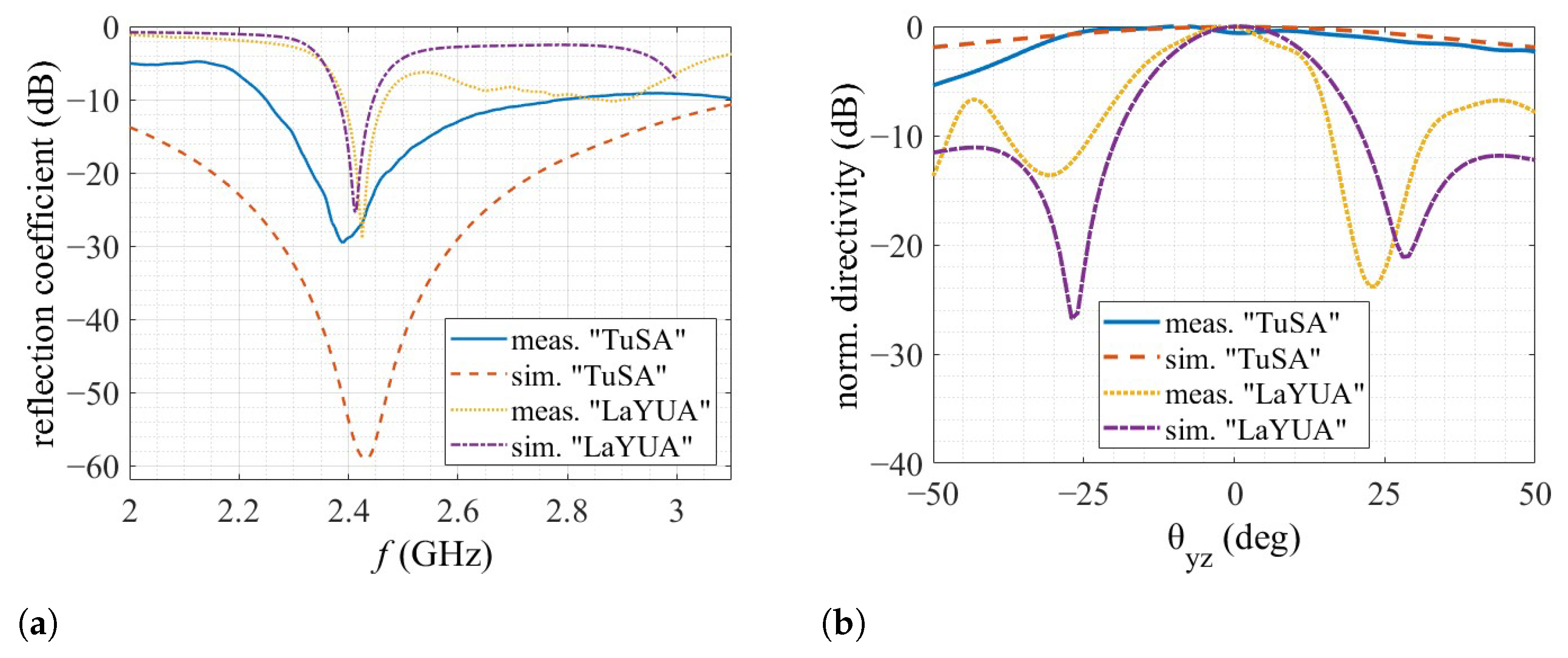
3.1. Antenna Measurements

The radiation pattern measurements were carried out in an anechoic chamber. Figure 3 shows photographs of the custom-designed antennas LaYUA and TuSA, which were implemented, respectively, on FR-4 substrates and mounted in the anechoic chamber. Figure 4 illustrates the simulated and measured reflection coefficient’s magnitude and normalized pattern at 2.4 GHz, when both the antennas are radiating into free space. There is a good agreement between the simulations and measurements. In this way, the simulated gain of the LaYUA and TuSA are about 9 dBi and 3 dBi, respectively.

3.2. System Performance Comparison

Figure 5 presents a comparative analysis of the four scenarios described above, using the three antennas, that tests their performance in terms of the bit error rate versus distance when a wireless communication takes place. These results are also very useful for understanding how capable different antenna configurations/devices are of preserving the signal quality as transmission distances get longer.
Scenario 1, utilizing commercial dipole antennas for both TxU and RxU, serves as the baseline and shows the poorest performance. The bit error rate rapidly increases to approximately 90% at 60 m. In contrast, Scenario 4, employing the LaYUA for TxU and the TuSA for RxU, demonstrates a remarkable improvement. At 60 m, Scenario 4 maintains a bit error rate of only about 10%, representing a significant improvement over Scenario 1. This better performance extends to the maximum tested distance of 100 m, where the Scenario 4 error rate remains below 40%, while Scenario 1’s approaches 100%, indicating an approximately 60% improvement in signal integrity at long range.
Scenario 2 and Scenario 3 offer intermediate improvements. At 60 m, Scenario 2 shows a bit error rate of 50%, an approximately 40% improvement over Scenario 1. Scenario 3 performs better that Scenario 2 up to 60 m but degrades rapidly beyond this point. At 80 m, Scenario 3 exhibits a bit error rate of about 90%, while Scenario 2 maintains one around 60%, demonstrating the 30% improvement of Scenario 2 over Scenario 3 at this distance. Notably, Scenario 4 outperforms all others consistently, showing a 40% lower error rate compared to Scenario 2 and a 70% improvement over Scenario 3 at the 80-meter mark. These quantitative comparisons underscore the substantial impact of antenna selection on wireless communication system performance, with the LaYUA-TuSA combination (Scenario 4) offering the most significant improvements in reliability and range.
This comparative analysis underscores the significant impact that antenna selection has on wireless communication system performance. Scenario 4, employing the LaYUA-TuSA configuration, demonstrates the most robust performance in terms of reliability and range, offering the lowest bit error rate, even at long distances. This makes it the most suitable for applications requiring strong signal integrity over large distances.

3.3. Discussion

The results presented in Figure 4a show that the measured reflection coefficients for both the LaYUA and TuSA antennas align well with the simulated results. This suggests that the designs of these antennas are robust and their performance characteristics in real-world conditions closely match theoretical expectations. Furthermore, the bandwidth of approximately 300 MHz for the LaYUA antenna is particularly advantageousfor various applications within the 2.4 GHz frequency range, as it ensures stable communication across a wide spectrum. In contrast, the TuSA exhibits a much wider bandwidth, which could contribute to its more stable performance over varying environmental conditions and distances.
The simulated and measured radiation patterns on the azimuth plane (ϕ = 90°) shown in Figure 4b agree very well within the half-power beamwidth for both antennas, thus, the simulated antenna characteristics are verified.
The high directivity of the LaYUA antenna plays a critical role in its superior performance, particularly in scenarios requiring long-distance communication. Directivity, in this case, refers to an antenna’s ability to focus the signal in a specific direction, thus minimizing energy loss and enhancing the effective signal strength at the receiving end. This is clearly demonstrated in Scenario 4, where the use of the LaYUA at the transmission unit (TxU) significantly improves the overall system performance compared to the baseline configuration (Scenario 1). The reduced bit error rate (BER) across increasing distances demonstrates the advantage of this high-gain antenna for long-range applications.
In contrast, the commercial dipole antennas used in Scenario 1 are omnidirectional, meaning they radiate energy equally in all directions. While this provides coverage over a wider area, it also dilutes the signal strength in any specific direction, leading to a higher BER as the distance increases. At 60 m, the BER for Scenario 1 reaches approximately 90%, whereas Scenario 4 (the LaYUA and TuSA combination) maintains a BER of only 10%. This drastic improvement highlights the importance of using antennas with focused radiation patterns for long-distance wireless communication.
The benefits of using the LaYUA in combination with the TuSA include the high directivity of the quasi Yagi-Uda structure, which enables long-distance communication and has the best performance, as shown in Figure 5. Additionally, the circular polarization characteristic of the TuSA reduces the need for exhaustive polarization calibration to ensure a clear line of sight.
The better performance of Scenario 4 in Figure 5 can be attributed to the combined characteristics of the utilized radiators. Both Scenarios 2 and 4 employ the LaYUA, known for its high directivity, which significantly enhances signal focus. However, Scenario 4 is further enhanced by the inclusion of a turnstile antenna, which is polarization-independent due to its circular polarization [15]. This combination leverages the high directivity of the LaYUA at the TxU and the polarization versatility of the TuSA at the RxU, resulting in the best bit error rate performance across all tested scenarios.
In Scenarios 2 and 3, where only one custom antenna is used, the performance is still markedly better than the baseline, but not as good as when both custom antennas are used. This suggests that while each antenna independently offers performance improvements, the combination of both the high-directivity LaYUA and the polarization-independent TuSA offers the most significant benefits. At 80 m, Scenario 4 maintains a BER of about 40%, whereas Scenario 1 approaches 100% and Scenario 3 reaches 90%. This underscores the complementary nature of the LaYUA and TuSA antennas in enhancing communication’s reliability and range.

4. Conclusions

In this work, a performance comparison, in terms of the bit error rate versus distance of an IoT communication system, has been evaluated using four scenarios with three antennas each attached to the Tx and Rx RF modules of NRF24L01. For the evaluation, a commercial dipole of the brand Siretta, a previously designed frequency-scaled Landstorfer Yagi-Uda antenna (LaYUA), and a turnstile antenna (TuSA) were utilized.
The LaYUA, with a directivity of about 9 dBi and horizontal polarization, was optimized with parameterized elements to enhance its performance, along with the TuSA, which features a directivity of about 3 dBi and circular polarization to provide consistent omnidirectional reception. The results illustrated that the combination of the LaYUA for the TxU and the TuSA for the RxU (Scenario 4) shows the best performance. At a distance of 60 m, this scenario maintained a bit error rate (BER) of approximately 10%, representing a 60% improvement over the baseline Scenario 1 (commercial dipole antennas), which exhibited a 90% BER. Even at 100 m, Scenario 4 kept the BER below 40%, significantly outperforming the baseline, which approached a 100% BER. This represents a substantial reduction in transmission errors, making it the most reliable and effective solution for long-range wireless communication. Therefore, the results suggest that high-performance antennas like those in Scenario 4 are essential for applications requiring extended transmission distances and reliable data integrity.
The results demonstrated that using non-commercial antennas like the custom radiators designed herein significantly enhanced wireless communication performance, particularly by reducing bit error rates over longer distances. This approach highlighted the substantial benefits of employing specialized antennas to optimize wireless systems, particularly in environments where standard commercial antennas may be insufficient. Using the LaYUA in combination with the TuSA enables many IoT devices to function effectively in remote environments such as agriculture, energy grids, and environmental monitoring. This combination facilitates robust communication between nodes, reducing data loss and ensuring reliable monitoring over larger areas.

Author Contributions

Conceptualization, J.G.A. and M.V.B.; methodology, J.G.A., M.V.B. and A.R.N.; validation, J.G.A., M.V.B., and A.R.N.; investigation, J.G.A., M.V.B. and C.Y.V.; writing—original draft preparation, J.G.A., M.V.B. and C.Y.V.; writing—review and editing, A.R.N. and H.B.M. All authors have read and agreed to the published version of the manuscript.

Funding

This research received no external funding.

Institutional Review Board Statement

Not applicable.

Informed Consent Statement

Not applicable.

Data Availability Statement

Data are contained within the article.

Conflicts of Interest

The authors declare no conflicts of interest.

Abbreviations

The following abbreviations are used in this manuscript:
FR-4Flame retardant-4: woven glass-reinforced epoxy resin
RFRadio Frequency
TxUTransmission unit
RxUReception unit
SPISerial Peripheral Interface
LaYUALandstorfer Yagi-Uda Antenna
TuSATurnstile antenna
BERBit error rate

References

  1. Rappaport, T.S. Wireless Communications: Principles and Practice; Cambridge University Press: Cambridge, UK, 2024. [Google Scholar]
  2. Hanes, D.; Salgueiro, G.; Grossetete, P.; Barton, R.; Henry, J. IoT Fundamentals: Networking Technologies, Protocols, and Use Cases for the Internet Of Things; Cisco Press: Indianapolis, IN, USA, 2017. [Google Scholar]
  3. Rathod, N.; Jain, P.; Subramanian, R.; Yawalkar, S.; Sunkenapally, M.; Amrutur, B.; Sundaresan, R. Performance analysis of wireless devices for a campus-wide IoT network. In Proceedings of the 2015 13th International Symposium on Modeling and Optimization in Mobile, Ad Hoc, and Wireless Networks (WiOpt), Mumbai, India, 25–29 May 2015; IEEE: Piscataway, NJ, USA, 2015; pp. 84–89. [Google Scholar]
  4. Kulkarni, P.; Hakim, Q.O.A.; Lakas, A. Experimental evaluation of a campus-deployed IoT network using LoRa. IEEE Sens. J. 2019, 20, 2803–2811. [Google Scholar] [CrossRef]
  5. Shen, P.; Qi, Y.; Yu, W.; Fan, J.; Li, F. OTA measurement for IoT wireless device performance evaluation: Challenges and solutions. IEEE Internet Things J. 2018, 6, 1223–1237. [Google Scholar] [CrossRef]
  6. IEEE Standard for Information Technology—Telecommunications and Information Exchange Between Systems—Local and Metropolitan Area Networks—Specific Requirements—Part 11: Wireless LAN Medium Access Control (MAC) and Physical Layer (PHY) Specifications—Amendment 4: Enhancements for Very High Throughput for Operation in Bands below 6 GHz; IEEE: Piscataway, NJ, USA, 2013; IEEE Standard No. 802.11ac-2013.
  7. Vakaliuk, T.A.; Andreiev, O.V.; Dubyna, O.F.; Korenivska, O.L.; Andreieva, Y.O. Wireless technologies in IoT projects with distributed computing. In Proceedings of the Doors 2024, 4th Edge Computing Workshop, Zhytomyr, Ukraine, 5 April 2024; pp. 4–13. [Google Scholar]
  8. De, B.; Karmakar, A. Arduino based RF Compact Module for Short Range Wireless Communication using nRF24L01. Int. J. Eng. Res. Technol. (IJERT) 2022, 10, PANE-2021. [Google Scholar]
  9. Anchidin, L.; Lavric, A.; Mutescu, P.M.; Petrariu, A.I.; Popa, V. The Design and Development of a Microstrip Antenna for Internet of Things Applications. Sensors 2023, 23, 1062. [Google Scholar] [CrossRef] [PubMed]
  10. Thiruvenkadam, S.; Parthasarathy, E.; Mythali, N.R.; Jevalikar, R.; Agarwal, A. Design and analysis of UWB antenna for IoT applications. AIP Conf. Proc. 2023, 2946, 060003. [Google Scholar] [CrossRef]
  11. Reyes Narváez, A.; Barba Molina, H. Landstorfer Antenna Structure Shaping Based on Parameterized Parallel Curves. In Proceedings of the Emerging Research in Intelligent Systems; Olmedo Cifuentes, G.F., Arcos Avilés, D.G., Lara Padilla, H.V., Eds.; Springer Nature: Cham, Switzerland; Sangolquí, Ecuador, 2023; pp. 61–71. [Google Scholar] [CrossRef]
  12. V, D.K.; Bhardwaj, A.; Mishra, D. Investigation of a turnstile nanoantenna. Micro Nano Lett. 2011, 6, 94–97. [Google Scholar] [CrossRef]
  13. Kraus, J.D.; Marhefka, R.J. Antennas for all applications. In Antennas for all Applications; McGraw-Hill Professional: New York, NY, USA, 2002. [Google Scholar]
  14. Semiconductor, N. nRF24L01 Single Chip 2.4GHz Transceiver. 2017. Availabel online: https://www.nordicsemi.com/Products/nRF24-series (accessed on 29 August 2024).
  15. Balanis, C.A. Antenna Theory: Analysis and Design, 3rd ed.; John Wiley & Sons, Inc.: Hoboken, NJ, USA, 2005. [Google Scholar]
Figure 1. Proposed experimental setup used to evaluate the IoT communication system’s performance by using custom-designed antennas.
Engproc 77 00016 g001
Figure 2. Antennas under test. (a) Modified shape-optimized Landstorfer Yagi-Uda antenna (LaYUA). (b) Printed turnstile antenna (TuSA) with 90°-phase-shift feeding between U1 and U2 sources, realized with a coaxial line.
Engproc 77 00016 g002
Figure 3. Photographs of the antenna prototypes mounted in an anechoic chamber, along with the definition of their spherical coordinates. (Left) LaYUA. (Right) TuSA.
Engproc 77 00016 g003
Figure 4. Measured (solid blue and dotted yellow) and simulated (dashed red and dash–dot violet) antenna results. (a) Reflection coefficient magnitude. (b) Normalized radiation pattern on the azimuth plane (ϕ = 90°) at 2.4 GHz. The results are invalid in a sector between 50° and 180° due to the measurement setup.
Engproc 77 00016 g004
Figure 5. BER obtained from measurements. Scenario 1 (solid blue): commercial dipole (TxU)–commercial dipole (RxU). Scenario 2 (dashed red): LaYUA (TxU)–commercial dipole (RxU). Scenario 3 (dotted yellow): commercial dipole (TxU)–TuSA (RxU). Scenario 4 (dash–dot violet): LaYUA (TxU)-TuSA (RxU).
Engproc 77 00016 g005
Disclaimer/Publisher’s Note: The statements, opinions and data contained in all publications are solely those of the individual author(s) and contributor(s) and not of MDPI and/or the editor(s). MDPI and/or the editor(s) disclaim responsibility for any injury to people or property resulting from any ideas, methods, instructions or products referred to in the content.

