Abstract
In the automotive industry, the reduction of development costs is of key importance. The development of electrical hardware is an expensive, time-consuming process with a lot of development stages (e.g., prototyping, electrical testing, mechanical testing, lifecycle testing). There is a growing need to increase the cost-effectiveness of the development and testing phases of embedded software using virtualization. Using this method, less prototype manufacturing is necessary since the simulations allow for faster and more effective discovery of a large portion of possible faults without building a hardware prototype. Renode is an open source embedded system simulation framework that facilitates software-based testing. The main goal of this paper is to explore the usability of the framework for automotive applications.
1. Introduction
The electronic control units installed in new cars usually run some kind of embedded software to ensure proper operation. The development time for these controllers is long, and the repeated prototyping and testing increases costs.
In addition to embedded software development, it is also important to develop the necessary hardware. However, this task involves continuous prototype testing and redesign based on the test results, with many iterations. It is also time-consuming and costly. The purpose of simulating hardware and software together is to verify that the hardware and software work together properly. This task is traditionally performed after the prototype hardware has been built, but if this verification can be performed in a virtual environment, the cost of prototyping and any iterations, and the time required for development, can be reduced.
Electronic control units (ECUs) in automotive electronic systems can suffer functional failure due to interference between the analog signals generated on the circuit and the binary signals used in the microprocessor of the control unit [1]. Functional testing for such failures is currently performed experimentally in the industry and is lengthy, may be performed late in the development phase when physical prototypes are available, and is time-consuming to correct and retest. Development is often delayed because of hardware supply difficulties, and debugging on real hardware is also difficult. For all these reasons, testing the functional robustness of automotive electronic systems is costly and time-consuming [2].
For this reason, the automotive industry would be very interested in the availability of an industrially applicable virtual robustness testing method that can test the functional robustness of automotive electronic systems through computer simulations [3,4,5,6].
A software toolbox that allows for virtual functional testing of control units of automotive electronic systems is necessary. The goal is to examine a simulation methodology that is suitable for virtual functional testing of electronic components [7]. This can be used in all areas where the following aspects are important:
- early screening of design errors;
- shortening development time;
- increasing test coverage and efficiency of testing;
- significant reduction of testing costs;
- minimizing the use of hardware elements.
Such a solution could be used in any electronic system design process that requires functional testing of control units, co-simulation of analog and digital circuits, or robust design and operation. Unfortunately, there is a lack of information available on applicable software solutions in the scientific literature. Most available tools from Synopsys and Cadence focus on semiconductor design and instruction set validation. Other simulators, such as LabCenter Proteus and DesignSoft TINA, are not open source and it is hard to extend their microcontroller models [8,9]. Hence, the aim of this study is to explore if it is possible to apply Renode to handle the virtualization of the electrical development tool chain.
2. What Is Renode?
Renode is an open-source emulator software solution for embedded platforms. It is an instruction set simulator that supports various architectures out of the box, such as x86 (Intel Quark), ARM Cortex-A, Cortex-M, SPARC, and RISC-V, and thanks to its open-source nature, it can be further extended. It can be used to assemble virtual system-on-chips from building blocks, as various microcontroller types (e.g., Cortex-M, Cortex-A) and different peripheral models (Figure 1). Hence, it is also possible to emulate microcontrollers used in automotive control. The unmodified production firmware can run against the emulated cores, peripherals, and even configured sensors and actuators. The parameters (e.g., memory addresses, peripherals, etc.) of the emulated embedded system are defined in text-based configuration files, while the functionality is modeled in C#.
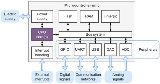
Figure 1.
The microcontroller and the connecting peripherals.
Using Renode, rapid software development and debug capabilities can be realized without evaluation hardware as in the standard IDE design flow. Most of the integrated development environments can be used, the only requirement is to be able to connect to GDB Server for debugging.
3. Renode System as a Virtual Platform
Platforms in Renode are modeled with the system bus (identified as sysbus) of the machine functioning as the central building block to which the peripherals are connected. All peripherals are accessible from anywhere within the created platform.
The real hardware might use a variety of intricately connected buses, but the same platform in Renode will just use a single bus. This simplification does not usually impact the behavior of the simulation in any way, as the structure of the interconnect in the SoC is hidden from the software perspective.
There are necessary configuration files to define the MCU and development board for the emulation. It is possible to automatically start the environment using these text-based configuration files.
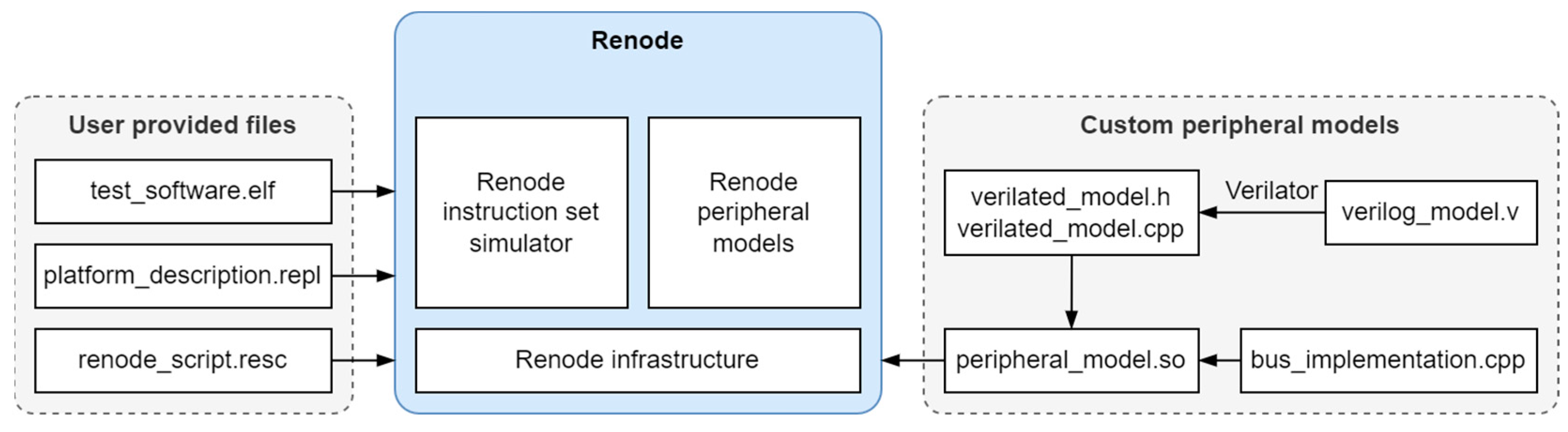
A Renode simulation typically involves a few key files that work together to define and execute the simulation environment in Renode. The typically involved files are shown in Figure 2.

Figure 2.
The files that are typically involved in a Renode simulation.
The Renode script file (extension .resc) contains the commands to create a virtual machine, load the board file and other necessary extensions for logging. This makes it possible to automate the command line operations. The Renode platform definition file (extension .repl) includes the description of the MCU (e.g., CPU and peripherals) and the board. This script loads the processor description and the configuration of the hardware connections for the system (e.g., GPIO connecting to an LED). Renode is also capable of loading custom peripheral models developed in Verilog or C++ [10].
4. Implementation of an STM32F4-Based Discovery Board
The STM32F4 family is a series of 32-bit microcontrollers developed by STMicroelectronics. These microcontrollers are based on the high-performance ARM Cortex-M core’s rich set of peripherals. The STM32F4 Discovery Board is a popular development board that leverages the capabilities of the STM32F407 microcontroller (embedded debug tool, a digital accelerometer, LEDs, push-buttons). This board is designed to help users easily develop and test applications, particularly those involving audio processing.
An STM32F4 Discovery Board emulation is used in this article for testing the setup of a simulation with Renode. Figure 3 shows the memory address space of Cortex-M4 CPUs with the configuration files set up with the same parameters as below [11].
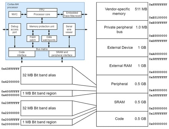
Figure 3.
The block scheme of the Cortex-M4 CPU (top left) and the memory address space.
In Renode, after a virtual machine is created, it contains only one peripheral, the system bus, called simply sysbus. At this point there is no CPU or memory, so the machine is not yet ready to execute any code. Renode uses a text-based format to describe platforms.
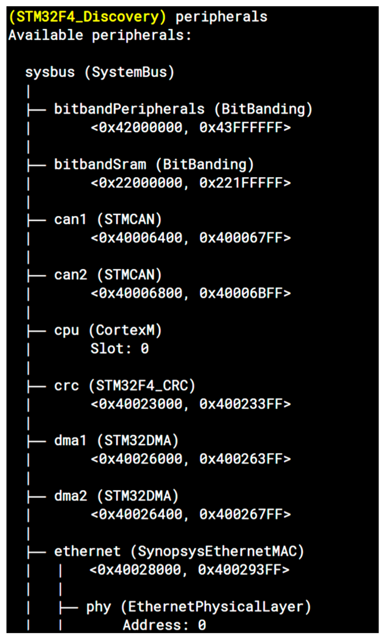
After loading the necessary board file with the predefined platform definition (platform description file) in the Renode terminal window, all the peripherals get configured and the virtual machine is ready to use. All the configured peripherals can be listed and a binary file can be loaded to test and debug against the emulation (Figure 4).
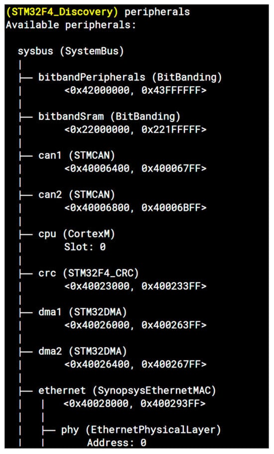
Figure 4.
Defined peripherals for STM32F4 in Renode terminal window.
5. Debugging
Virtual debugging is the most important function that is necessary to handle the virtualization of the ECU development. The virtual machine can be used to debug the binary code using the GDB remote protocol. The general GDB functions (e.g., breakpoints, stepping, memory access) can be used to examine the binary code against the virtual hardware while it runs. Debugging on real hardware and virtual debugging differ significantly in time requirements; the debugging process is transparent for emulated machines, since the virtual time does not progress when the emulated CPU is halted.
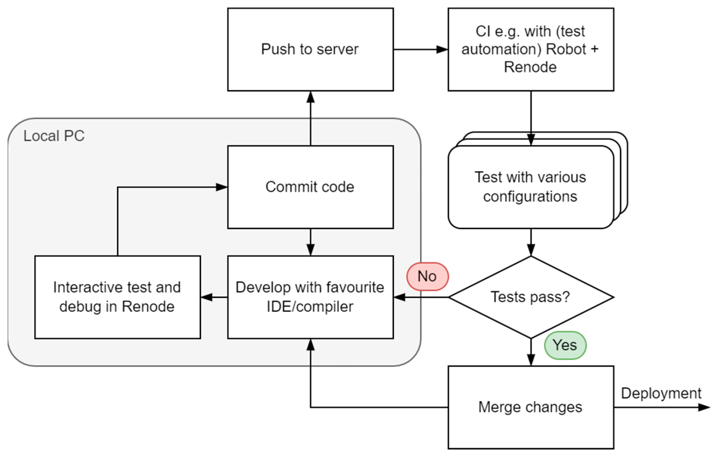
Process is simpler because of the deterministic time flow; it is possible to stop the debug process for the whole system at the same time. It is well suited to being part of an automated tests scenario, e.g., running in the background on a CI server. Renode is integrated with the Robot Framework testing suite, can be used with other test automation environments, and provides user-friendly scripts for running tests (Figure 5).
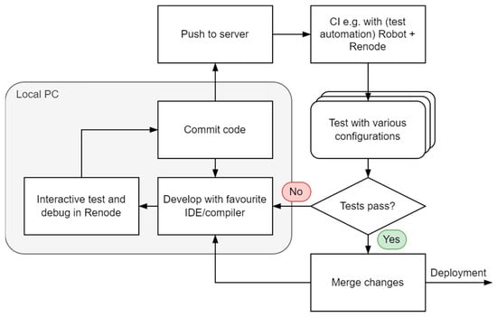
Figure 5.
The development and testing process with Renode.
Provided that the binary (the compiled .elf file) executed contains a symbol map (as it normally does during the development process), it can trace its execution, get detailed logs including executed function names, peripheral accesses, and opcode counting, generate code coverage reports, and use advanced GDB integrations. Renode is also equipped with a built-in disassembler and metrics analyzer to mock elements of a device using tags, integrates with external analyzers like Wireshark, and allows for use of hooks to monitor or alter the execution of the binaries, e.g., by spoofing registers/memory states or injecting (network, CAN, etc.) messages to trigger behaviors of software.
6. Conclusions
Nowadays, in a new car there are many control units that operate switches and actuators based on sensor data. An increasing amount of data flows between these units in an increasingly complex way. As a result, development and testing procedures are becoming increasingly complex too.
Using Renode, it is possible to create virtual test cases, in which the corresponding tests can be assigned to virtual nodes connected via known communication channels (e.g., Ethernet, CAN, wifi, etc.). This makes prototype testing much more flexible, speeding up the overall testing process. The benefits of simulation are obvious, as the complexity of automotive systems is constantly increasing, especially for new hardware components where decisions have to be made on whether a new hardware component can be adapted to specific projects.
Renode is relevant framework to use to support automotive development due to its test integration capabilities, the increasing coverage of hardware (supporting different instruction set architectures), and the possibility of automation. Further research should connect to SPICE-based electric circuit simulation.
Author Contributions
Conceptualization, F.S., D.F. and I.S.; methodology, I.S. and F.S.; validation, F.S.; investigation, I.S.; resources, I.S. and F.S.; writing—original draft preparation, F.S. and I.S.; writing—review and editing, F.S., D.F. and I.S. All authors have read and agreed to the published version of the manuscript.
Funding
The research was funded by the European Union within the framework of the National Laboratory for Autonomous Systems (RRF-2.3.1-21-2022-00002).
Institutional Review Board Statement
Not applicable.
Informed Consent Statement
Not applicable.
Data Availability Statement
The raw data supporting the conclusions of this article will be made available by the authors on request.
Conflicts of Interest
The authors declare no conflicts of interest.
References
- Urbina, M.; Ahmadian, H.; Obermaisser, R. Co-simulation framework for AUTOSAR multi-core processors with message-based Network-on-Chips. In Proceedings of the 2016 IEEE 14th International Conference on Industrial Informatics (INDIN), Poitiers, France, 19–21 July 2016; pp. 1140–1147. [Google Scholar]
- Hseih, H.; Lavagno, L.; Passerone, C.; Sansoe, C.; Sangiovanni-Vincentelli, A. Modeling micro-controller peripherals for high-level co-simulation and synthesis. In Proceedings of the 5th International Workshop on Hardware/Software Co Design. Codes/CASHE’97, Braunschweig, Germany, 24–26 March 1997; pp. 127–130. [Google Scholar] [CrossRef]
- Gauthier, L.; Jerraya, A. Cycle-true simulation of the ST10 microcontroller. In Proceedings of the Design, Automation and Test in Europe Conference and Exhibition 2000 (Cat. No. PR00537), Paris, France, 27–30 March 2000; p. 742. [Google Scholar] [CrossRef]
- Gauthier, L.; Jerraya, A. Cycle-true simulation of the ST10 microcontroller including the core and the peripherals. In Proceedings of the 11th International Workshop on Rapid System Prototyping. RSP 2000. Shortening the Path from Specification to Prototype (Cat. No.PR00668), Paris, France, 21–23 June 2000; pp. 60–65. [Google Scholar] [CrossRef]
- Stecklina, O.; Vater, F.; Basmer, T.; Bergmann, E.; Menzel, H. Hybrid Simulation Environment for rapid MSP430 system design test and validation using MSPsim and SystemC. In Proceedings of the 14th IEEE International Symposium on Design and Diagnostics of Electronic Circuits and Systems, Cottbus, Germany, 13–15 April 2011; pp. 167–170. [Google Scholar] [CrossRef]
- Köhler, C. Enhancing Embedded Systems Simulation: A Chip-Hardware-in-the-Loop Simulation Framework; Vieweg+ Teubner Verlag: Wiesbaden, Germany, 2011. [Google Scholar] [CrossRef]
- Amringer, N.; Asemann, P. Simulation of Virtual ECUs in the context of ECU Consolidation. In Proceedings of the 9th AutoTest Technical Conference, Test of Hardware and Software in Automotive Development, Stuttgart, Germany, 19–20 October 2022. [Google Scholar]
- Janabi, A.; Agyeman, M. An Overview of Cycle-Accurate, Event-Driven and Full Systems Simulators for Chip-Multiprocessors. Int. J. Comput. Theory Eng. 2019, 11, 103–106. [Google Scholar] [CrossRef]
- Paknikar, R.; Bansode, S.; Nandihal, G.; Desai, M.; Moudgalya, K.; Jha, A. eSim: An Open Source EDA Tool for Mixed-Signal and Microcontroller Simulations. In Proceedings of the 2021 4th International Conference on Circuits, Systems and Simulation (ICCSS), Kuala Lumpur, Malaysia, 26–28 May 2021; pp. 212–217. [Google Scholar] [CrossRef]
- Deshpande, N.; Sadakale, R. AMBA AHB to APB Bridge Protocol Verification Using System Verilog. In Proceedings of the 2023 First International Conference on Advances in Electrical, Electronics and Computational Intelligence (ICAEECI), Tiruchengode, India, 19–20 October 2023; pp. 1–3. [Google Scholar] [CrossRef]
- STM32 Cortex®-M4 MCUs and MPUs Programming Manual. Available online: https://www.st.com/resource/en/programming_manual/pm0214-stm32-cortexm4-mcus-and-mpus-programming-manual-stmicroelectronics.pdf (accessed on 15 August 2024.).


Disclaimer/Publisher’s Note: The statements, opinions and data contained in all publications are solely those of the individual author(s) and contributor(s) and not of MDPI and/or the editor(s). MDPI and/or the editor(s) disclaim responsibility for any injury to people or property resulting from any ideas, methods, instructions or products referred to in the content. |
© 2024 by the authors. Licensee MDPI, Basel, Switzerland. This article is an open access article distributed under the terms and conditions of the Creative Commons Attribution (CC BY) license (https://creativecommons.org/licenses/by/4.0/).