Abstract
In this study, a rubber vibration isolator is designed for certain aerospace equipment, and a finite element simulation is carried out to obtain the modal frequency and random vibration response, and to verify the accuracy of the design. The test verifies that there is no amplification of vibration within 100 Hz; the damping efficiency values of vertical and horizontal random vibration are, respectively, 42.12% and 40.54%; and the impact isolation rate is more than 80%. The test results show that the vibration isolation buffer effect of the isolator is satisfactory and meets the design requirements.
1. Introduction
Vibration and impact are common phenomena that affect the accuracy and the working life of equipment. In severe cases, the equipment will fail and cause an accident. The mechanical environment of aerospace equipment is worse, and the equipment has higher requirements for precision. Therefore, it is necessary to choose a suitable vibration isolator to attenuate the vibration or impact transmitted to the equipment. When selecting a vibration isolator, it is necessary to take into account the limiting factors, such as the temperature, radiation, weight, shape, and size of the equipment.
2. Development of Research Questions
Jia Yan Liu [1] and others design a rubber vibrator for photoelectric pods that reduces the vibration value by more than 50%.They establishes a non-linear anti-impact theory model of rubber vibrations, derives the adhesive ultra-elasticity of this equation, and accurately describes the non-linear rubber vibrator impact response. Zhi Zhang [2] studies a dual-layer vibration and vibration-proof system for aerospace equipment, and analyzes its impact response to an 8000 g acceleration impact.
3. Methodology
The transfer coefficient TF of vibration isolation is equal to the ratio of the force amplitude FT acting on the foundation with the isolator and the force amplitude F0 acting directly on the foundation without the isolator, which is expressed as follows [3]:
In the formula, —dampen ratio, —natural frequency. The different damping curves intersect at the point (,1) when = , the transmission rate, is the largest in the resonance area. In order to make the vibrating system have a vibration suppression function, the transmission rate must be less than 1—that is, > . As the frequency ratio continues to increase, the transmission rate gets smaller and smaller. However, the frequency ratio should not be too large, otherwise the static deflection of the vibration device will be large, resulting in poor stability. Generally, the frequency ratio is between 2.5 and 5.0 [4]. The increase of damping ratio will reduce the vibration isolation effect. If the damping ratio is too small, it will cause the amplification factor and the resonance peak value to be too large. Therefore, the damping ratio should be set at 0.05~0.2.
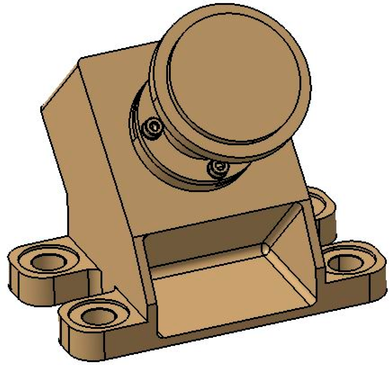
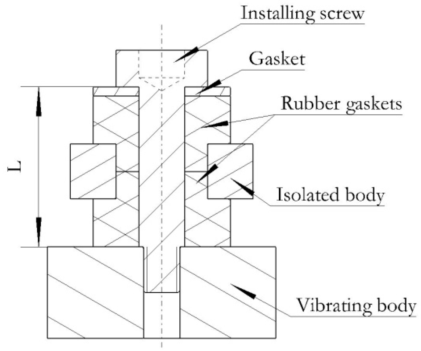
The aerospace equipment is shown in Figure 1. This structure requires a vibration isolator with small volume and easy installation. Rubber vibration isolators are chosen and installed in the ear holes. Each rubber vibration isolator is composed of a mounting screw, two rubber pads, and a gasket. The mounting screw cannot use ordinary screws. The length of the screw rod should be controlled according to the thickness of the rubber pad, in order to control the L value; generally the L value is greater than the thickness of the pad, which is 0.2 mm~0.4 mm, ensuring that the rubber vibration isolator is in a working state. A diagram of the rubber vibration isolator’s application structure is shown in Figure 2.
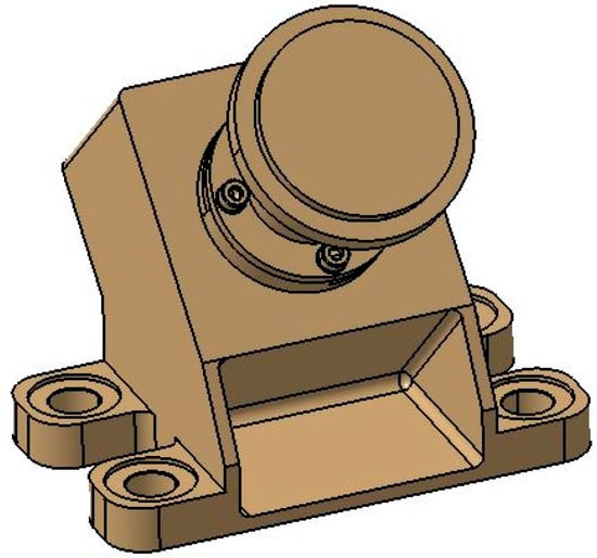
Figure 1.
The structure of the aerospace equipment.
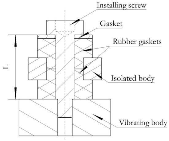
Figure 2.
A diagram of the rubber vibration isolator’s application structure.
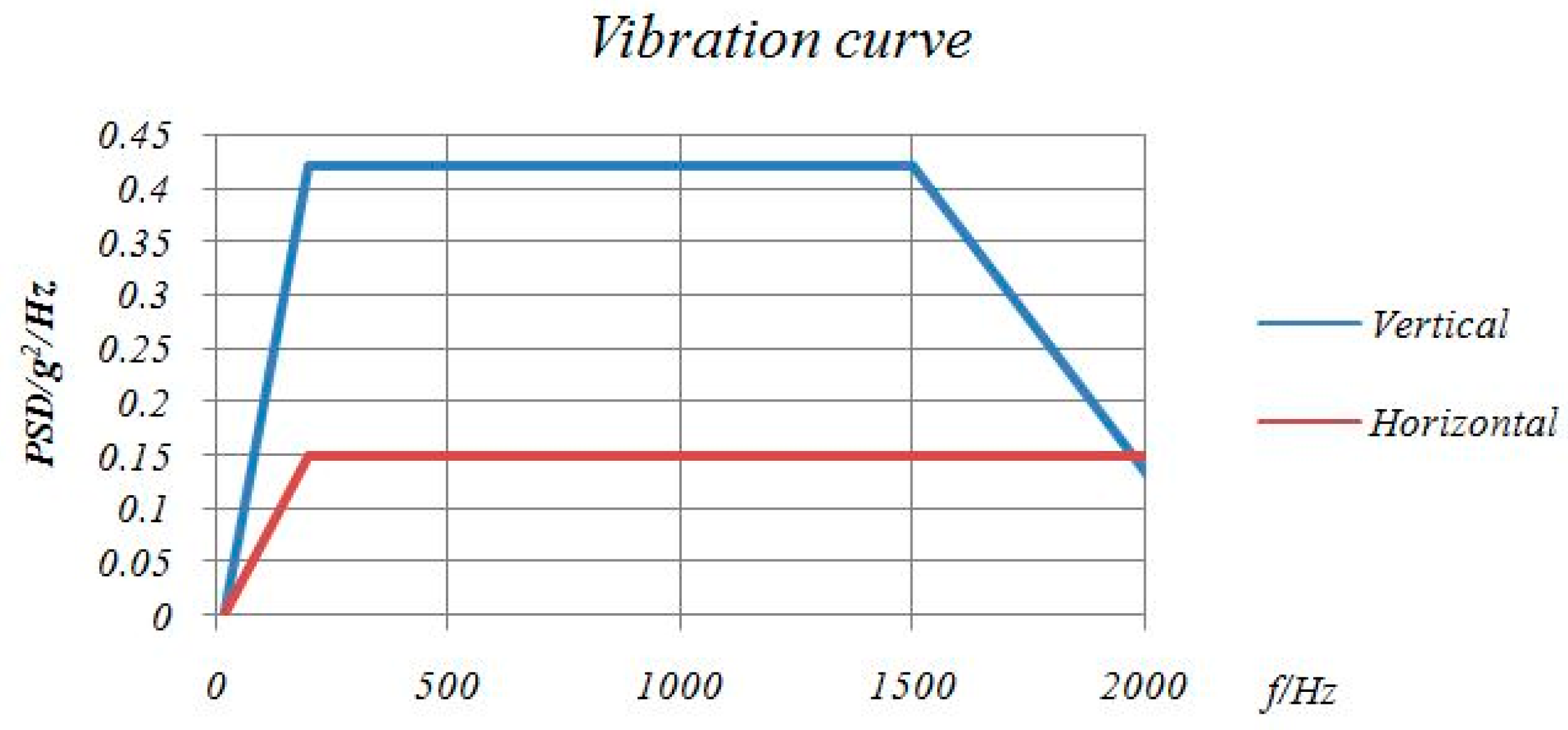
The main mechanical conditions to which space equipment is subjected include sine vibration, random vibration, and impact. The operating range of sine vibration is from 5 Hz to 100 Hz, and the random vibration condition is shown in Figure 3. The root mean square values of the acceleration of vertical and horizontal random vibration experienced by space equipment are, respectively, 26.4 g and 16.7 g. The test condition of impact is a +9 dB/Oct oblique line in the range of 100 Hz to 1500 Hz, and the acceleration amplitude is 2100 g in the range of 1500 Hz to 4000 Hz. Sine is not allowed to be amplified within 100 Hz. According to previous experience, the natural frequency of the rubber vibration isolator is generally not less than 150 Hz, otherwise it will cause resonance amplification. According to calculations, when the natural frequency of the isolator is 150 Hz, the vertical and horizontal random vibration response values are, respectively, 14.67 g and 8.77 g, and the corresponding vibration reduction efficiency values are, respectively, 44.38% and 47.61%.
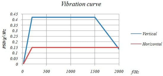
Figure 3.
Random vibration test spectrum.
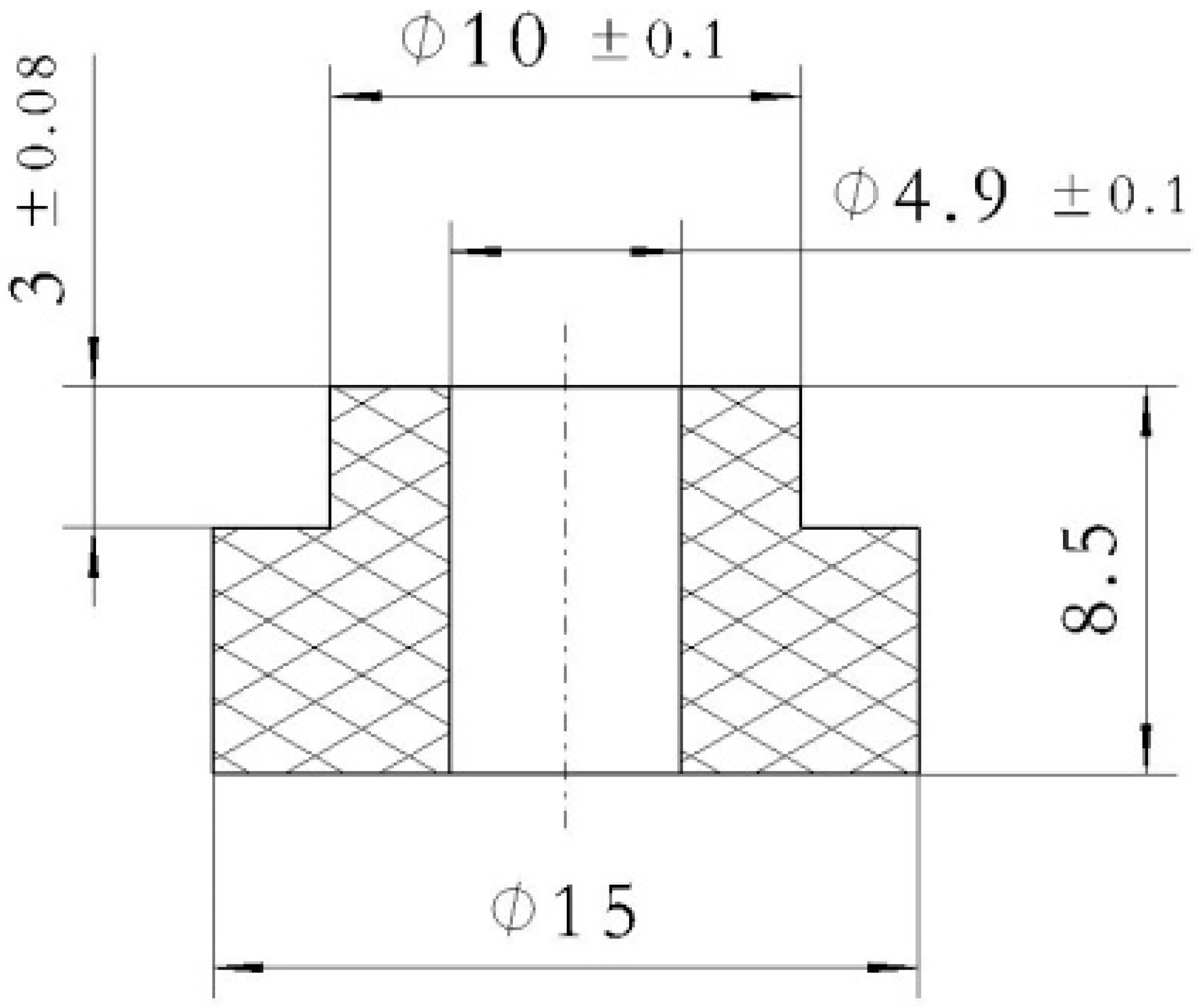
According to Formula (2), the dynamic stiffness of the isolator can be calculated as K = 355.32 N/mm; in order to facilitate calculation, assuming that the stress–strain relationship of the rubber vibration device is linear, the relationship between static stiffness Ks and the compression modulus Ec is shown in Formula (3), where h is the effective height of the shock absorber and S is the bearing area of the vibration isolator. The ratio of dynamic stiffness K to static stiffness Ks is generally 1.2~2 [5], which is set at 1.5, and the static stiffness Ks is 236.88 N/mm. According to Formula (3), the overall dimensions of a single rubber pad can be obtained, as shown in Figure 4. The rubber material is self-developed, and according to the temperature DMA curve of the rubber material, it can meet the requirement of −50 °C~120 °C.
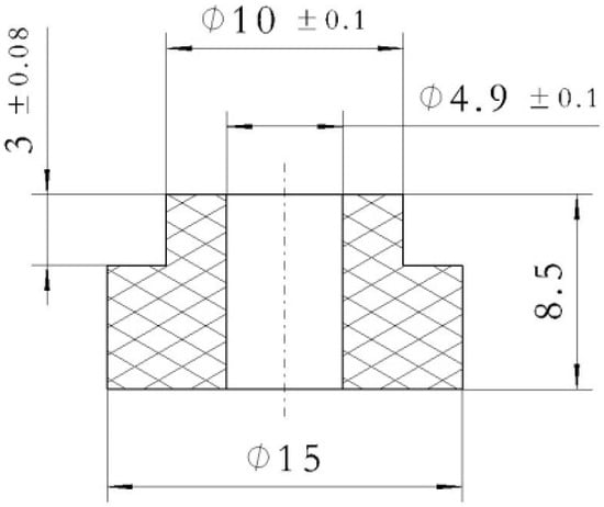
Figure 4.
A drawing of the rubber pad dimensions.
4. Results and Analysis
In order to ensure the feasibility of the vibration isolator’s design and accelerate development progress, a finite element simulation (FES) is carried out in the scheme stage, where the vibration isolator is simplified into a single degree of freedom stiffness-damping element. According to the vibration patterns, the first and second modes are rotation modes, but the third mode is a translational mode, which is 149.39 Hz. This is consistent with the design. Finite element simulations of vertical and horizontal random vibration are carried out. The vibration curve roughly goes through three stages of follow-amplifying and vibration isolation. The vertical and horizontal acceleration power spectral density values are, respectively, 16.45 g and 10.15 g, and the corresponding vibration reduction efficiency values are, respectively, 37.69% and 39.22%.
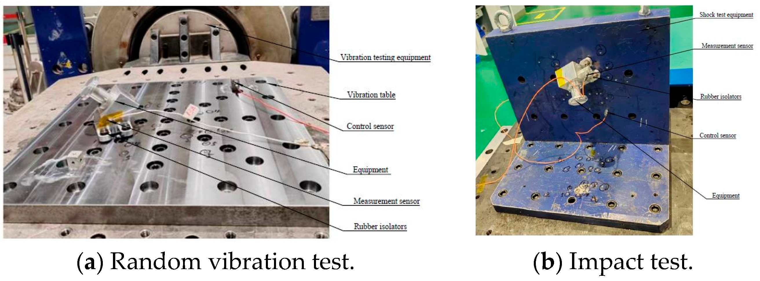
The vibration and impact tests are, respectively, carried out on a shaking table and a shock spectrum response table. The test component system includes the shaking table, the shock spectrum response table, the equipment, rubber vibration isolators, a control sensor, and a measurement sensor, as shown in Figure 5. The sine vibration test results show that no vibration amplification occurs in the range of 100 Hz, which indicates that the natural frequency design is reasonable. The random vibration test results show that the vertical and horizontal acceleration power spectral densities are, respectively, 15.28 g and 9.93 g, and the corresponding vibration reduction efficiencies are, respectively, 42.12% and 40.54%. The impact test results show that the vertical and horizontal acceleration response values are, respectively, 300 g and 250 g, and the impact isolation rate reaches more than 80%. Those three test results show that the vibration isolation buffer effect of the isolator is excellent, and the design expectation is reached.
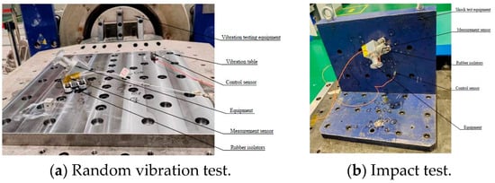
Figure 5.
The test component system diagram.
5. Discussion and Conclusions
In this study, a rubber vibration isolator is designed for certain aerospace equipment. According to the basic principles of vibration isolation, the appropriate natural frequency is selected, the outer dimension of the rubber pad is determined, and the modal frequency and random vibration response are obtained by finite element simulation to verify the accuracy of the design. The test verifications are carried out, and it is found that no vibration amplification occurs within the range of 100 Hz. The acceleration power spectral density values of vertical and horizontal random vibration are, respectively, 15.28 g and 9.93 g, and the corresponding vibration reduction efficiency values are, respectively, 42.12% and 40.54%. The acceleration response values of vertical and horizontal impact are, respectively, 300 g and 250 g, and the impact isolation rate reaches more than 80%. The test results show that the vibration isolation and buffering effects of the isolator are excellent and meet the design expectations.
Author Contributions
Conceptualization, K.D. and F.H.; methodology, K.D.; software, F.H.; validation, K.D.; writing-original draft preparation, K.D.; writing-review and editing, K.D. and F.H. All authors have read and agreed to the published version of the manuscript.
Funding
This research received no external funding.
Institutional Review Board Statement
Not applicable.
Informed Consent Statement
Not applicable.
Data Availability Statement
Data are contained within the article.
Acknowledgments
The both authors would like to thank colleagues for their support of this study, especially for their help with the test equipment.
Conflicts of Interest
Author Ke Duan was employed by the company Xi’an ASRIC Aviation Technology Co., Ltd. The remaining authors declare that the research was conducted in the absence of any commercial or financial relationships that could be construed as a potential conflict of interest. The company Xi’an ASRIC Aviation Technology Co., Ltd.-companies in affiliation and funding had no role in the design of the study; in the collection, analyses, or interpretation of data; in the writing of the manuscript, or in the decision to publish the results.
References
- Liu, J.Y.; Cheng, Z.F.; Wang, P. Design and application of rubber shock absorber for airborne photoelectric pod. China Mech. Eng. 2014, 25, 1308–1312. [Google Scholar]
- Zhang, Z.; Zhang, Z.H.; Dong, S. Research on shock response of rubber double-layer vibration reduction and isolation system. Vib. Shock. 2013, 32, 126–129. [Google Scholar]
- Yan, D.J.; Tang, D.G.; Qian, Q.H. Isolation properties of double mass-spring system under blast shock and vibration. J. Vib. Eng. 2001, 14, 339–344. [Google Scholar]
- Li, H.G.; Peng, X. Shock response of two degrees of freedom isolation system with isolator of nonlinear stiffness. J. Noise Vib. Control. 2007, 27, 21–26. [Google Scholar]
- Gong, X.S.; Xie, Z.J. Research on damping characteristics of nonlinear isolators. J. Vib. Eng. 2013, 14, 334–338. [Google Scholar]
Disclaimer/Publisher’s Note: The statements, opinions and data contained in all publications are solely those of the individual author(s) and contributor(s) and not of MDPI and/or the editor(s). MDPI and/or the editor(s) disclaim responsibility for any injury to people or property resulting from any ideas, methods, instructions or products referred to in the content. |
© 2025 by the authors. Licensee MDPI, Basel, Switzerland. This article is an open access article distributed under the terms and conditions of the Creative Commons Attribution (CC BY) license (https://creativecommons.org/licenses/by/4.0/).

