Proceeding Paper

Additive Manufacturing of a Customized Printed Ankle–Foot Orthosis: Design, Manufacturing, and Mechanical Evaluation †

1
Sección Bioingeniería, Pontificia Universidad Católica del Perú, Lima 15088, Peru
2
CITE Materiales, Pontificia Universidad Católica del Perú, Lima 15088, Peru
*
Author to whom correspondence should be addressed.
Presented at the III International Congress on Technology and Innovation in Engineering and Computing, Lima, Peru, 20–24 November 2023.
Eng. Proc. 2025, 83(1), 24; https://doi.org/10.3390/engproc2025083024
Published: 11 February 2025

Abstract

:
The ankle, a pivotal and intricate joint within human anatomy, is particularly susceptible to injuries, notably sprains, due to its complex structural composition and the substantial load it endures, especially among high-performance athletes, thereby necessitating the development of innovative, patient-specific rehabilitation solutions to address the challenges presented during the recovery process. In response to this, a non-surgical approach is proposed, involving the meticulous design and implementation of a personalized orthosis. It will be designed employing additive manufacturing with polyethylene terephthalate glycol (PETG), which facilitates immobilization while also enhancing breathability and comfort through the strategic incorporation of hexagonal holes. It demonstrates significant promise in its innovative design, customizability, and potential applicability, contributing to the broader field of biomechanics and orthopedic rehabilitation.

1. Introduction

Worldwide, ankle sprains have an incidence of 1 in 10,000 people in urgent care services, particularly in high-performance athletes [1]. In this pathology, there are three degrees of complexity. The most complex is the third one, which encompasses the total fracture of the ligand in the exterior of the ankle. This lesion is common among high-performance athletes, and it has a significant impact on the mobility and functionality of the ankle. It occurs when the ligands connecting the bones of the ankle stretch or break due to an excessive force, like a sudden turn [2].
Data from the Peruvian Ministry of Health report that ankle sprains are one of the most common lesions in sportsmen, indicating the necessity of efficiently organizing the process of postoperative rehabilitation to ensure a successful recovery. Statistics in Peru also indicate that the population at the highest risk of having a third-degree ankle sprain is in the age range of 20–49 years old, as they represent 42% of all incidences [3]. Between January 2019 and July 2023, Peruvian hospitals part of the national social security program (ESSALUD) treated 127 cases of ankle sprains. Out of these, 67 were derived from major surgery. It should be noted that this number does not take into account the number of cases attended in other hospitals or private clinics, which means the actual number could be much bigger. It is important to mention that the information described in this paragraph is not publicly available in a repository. Instead, it was obtained via direct contact with ESSALUD using a public access solicitude (Solicitud de Acceso a la Información Pública NIT 179-2023-15533), and can be retrieved via requesting it through the same channel.
The postoperative treatment consists of using an orthopedic splint or a cast in a neutral position on the ankle between 4 and 6 weeks, depending on the situation of the patient. At the same time, the rehabilitation process starts, focusing on the development of joint proprioception as part of an exercise program [4].
Despite the current treatments, such as the ones previously mentioned, there is a gap between precise immobilization and adequate support in sportsmen rehabilitation. Traditional solutions are generic and do not cover the individual necessities of each patient [5]. Additionally, these technologies do not take maximum benefit from the current technology of additive manufacturing, such as 3D printing, which allows for the creation of custom and anatomically precise devices.
Multiple articles have been reported that use this technology, particularly in the creation of ankle–foot orthoses (AFOs). Castillo et al. [6] report the design of one for the treatment of anterior/posterior cruciate ligaments. It was manufactured with high-impact polystyrene (HIPS), whose strain resistance was validated with tensile testing. Lin et al. cover the evaluation of the strength and modification of a 3D-printed AFO [7]. This research paper covers the feasibility of the results obtained via finite element analysis with mechanical testing in a universal testing machine. The conclusion the article arrives at is that with a higher thickness for the orthosis, a higher rigidity can be achieved when compared to traditional orthosis. Ho et al. cover a 3D-printed AFO of polyurethane by 3D printing, whose validation was carried out in a mechanical fatigue resistance test subjected to 300,000 repeated load cycles without showing damage or breakage, as well as a gait analysis (HWK-200RT®, Motion Analysis Corp., Rohnert Park, CA, USA), demonstrating slightly less effectiveness than conventional AFOs to correct plantar flexion caused by foot drop in exchange for greater comfort, lightness, practicality, and a more affordable cost [8]. Del Maso et al. discuss the design process to make a 3D-printed AFO made of polylactic acid (PLA). This article offers a series of steps to make photogrammetry that accurately obtains the autonomy of the foot of the patient, a method for proper strength testing and failure criterion for a proper finite element analysis, and, finally, printing parameters for a proper correspondence between the geometry of the orthosis and the foot of the patient [9]. The lack of additive-manufactured AFOs as an alternative to traditionally manufactured ones was found. Having researched the state of the art on the subject, it was decided to manufacture a 3D printed AFO, with a custom design accommodating to the size of the patient, as well as a design that could accommodate for better breathability in the region that would be constantly covered by the AFO.

2. Materials and Methods

For the development of the proposed AFO, various options for the material were evaluated. It was decided that polyethylene terephthalate glycol (PETG) was going to be used due to its mechanical properties, price, and wide use for orthosis [10]. eSUN PETG was acquired in black and white colors.
Having obtained the material, three tests were considered to evaluate the physical characteristics of the material. These were performed to verify that the properties of the acquired filaments coincided with those seen in the literature and the datasheet provided by the manufacturer. Tensile testing was carried out to assess the ultimate tensile strength and Young’s modulus of the material [11]. The test was performed in a Zwick–Roell Z050 machine (ZwickRoell GmbH, Ulm, Germany) with a 1kN load cell with 20 cm filament length strands and repeated 20 times [12]. Melt flow testing was performed to confirm the melt flow rate, with which an optimal printing temperature can be determined [13]. A Zwick–Roell mFlow machine (ZwickRoell GmbH, Ulm, Germany) was used at 190, 210, and 230 degrees Celsius with a load of 2.16 kg for each one [14]. A total of 5 g of filament was taken for the test and cut into tiny pieces. For each temperature, it was repeated 10 times. Finally, Fourier-Transform Infrared Spectroscopy (FT-IR) was evaluated to confirm the organic structure of the polymer [15]. The test was performed with a Bruker Tensor 27 IR machine (Bruker Optik GmbH, Ettlingen, Germany), where small pieces of PETG filament were cut and the prepared filament was placed in a spectrophotometer cell [16].

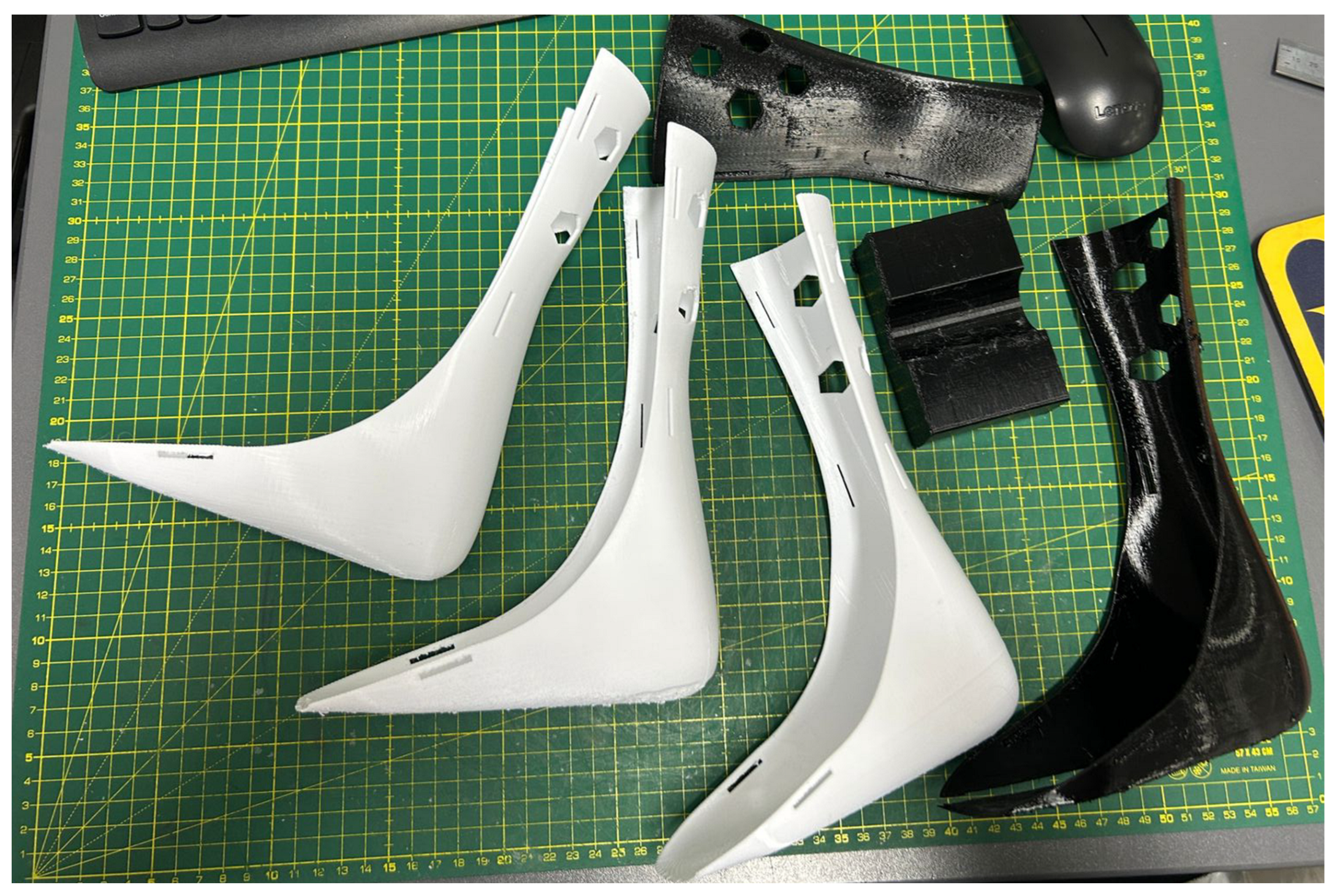
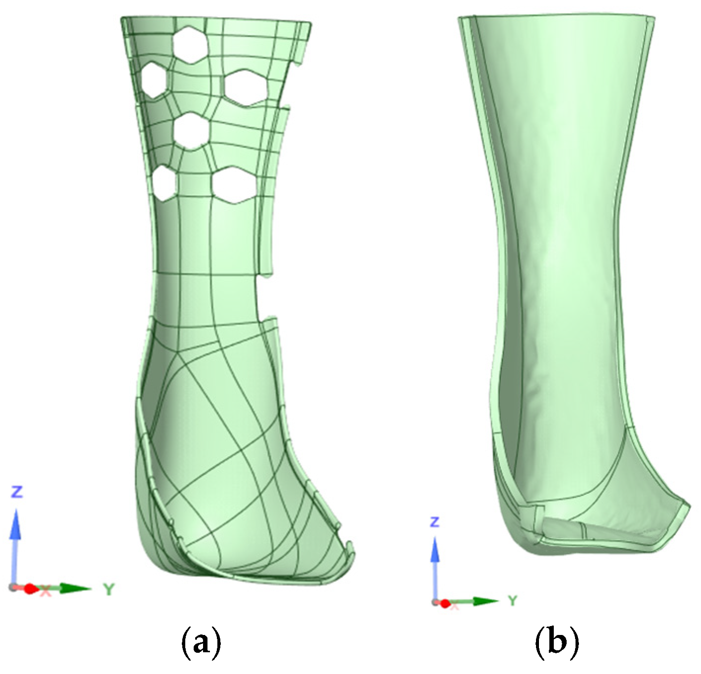
2.1. Fabrication and Modeling

To make the orthosis, the VDI2225 methodology was followed. The process started by 3D scanning the leg of a volunteer. A healthy, male, human was used as the test subject for this. The scanning was carried out in Pontificia Universidad Católica del Perú using a Sense 3D Scanner (3D Systems Inc., Rock Hill, SC, USA) [17]. For this, the volunteer laid horizontally on two chairs with their leg, ankle, and foot in the air. The body region was scanned in that position, visualized on its software and exported into an STL file.
The scanning process was prone to acquiring rough sections or more than was necessary. In order to mitigate this, the file was modified using Autodesk Meshmixer software v.3.5 (Autodesk, 2018) [18], which proved useful for the making of the orthosis. Unwanted regions were deleted and certain zones were smoothed in order to obtain a 3D model that only encompassed the desired region.
Following this, the model was imported into Autodesk Fusion 360 software v.2.0.14344 (Autodesk, 2023), where the AFO was modeled from the STL file [19,20]. Once the foot model was imported into the software, the initial step involved positioning it vertically on the coordinate axis for ease of manipulation. Our approach began with the creation of a cylindrical shape, which was used to completely encircle the leg area where the ankle–foot orthosis (AFO) would be applied. Subsequent modifications were made to the cylinder to conform to the foot’s contours.
Utilizing the “pull” tool, the cylinder was further refined to fully take on the shape of the foot, ensuring a precise fit. A thickness of 5 mm was applied to the model for structural integrity. Following this, unnecessary parts of the model, particularly those located at the front of the foot, were removed to streamline the design.
The next phase involved the creation of hexagonal patterns in the calf area for transpirability, along with rectangular slots designed for the passage of Velcro straps. These features were meticulously crafted using specific sketches to outline the shapes of the openings, combined with the “extrude” tool for accurate execution.
As a final step, the sole of the foot portion of the AFO was modified to be flat rather than contoured to the foot’s shape. This was deemed unnecessary for the functionality of the orthosis. The “flatten” tool was employed to achieve this, allowing us to create a level plane and flatten the sole relative to this plane, resulting in an improved overall design.
The resulting AFO was then imported into Cura 5.2.1 (Ultimaker, 2022) to prepare it and modify it for 3D printing [21]. A full protocol was developed, which can be seen in Table 1. Two different 3D printers were used, Artillery Genius and Artillery Sidewinder (Artillery3d, Shenzhen, China).
After printing, the supports were removed using a cutting plier. Velcro was added for extra support on the thigh region. A piece of cloth was added to the sole as a way to offer extra comfort for the patient. The whole process is summed up in Figure 1.
The orthoses were printed using Artillery Genius and Artillery Sidewinder 3D printers. In total, seven prototypes were printed. However, due to external effects, only four were deemed usable. The initial one was printed with a 0° angle with respect to the base of the printer. But, it was found to be too fragile, breaking shortly after testing. To avoid this issue, others were printed at −15° with respect to the base, avoiding the fragility issue. Some of the printed AFOs can be seen in Figure 2.

2.2. Evaluation Protocols

Two ways of mechanical evaluation of the AFOs were performed, before (computer simulation) and after printing (mechanical testing). Once the modeling phase is complete, simulations were performed using the ANSYS Student software, version 2023R1. ANSYS was used as engineering simulation software in the mechanical evaluation of AFOs by many authors [23]. Finally, once the AFOs were printed, they were subjected tomechanical testing.

2.2.1. Computer Simulation

The 3D models were used for an FE simulation using ANSYS® Workbench R23. The finite element method (FEM) consists of the model of an object made of a certain material, which is submitted to certain mechanical loads and analyzed for specific results, including stresses and strains, for instance, similarly, as seen in Figure 3. By analyzing the regions of stress concentration, the structural weaknesses of a part or object can be determined. With this tool, it is possible to predict where the orthosis is going to fail in order to make future reinforcements. Two models were tested using FE simulations.
Additionally, is necessary to define the PETG material in Ansys Engineering Data using parameters obtained from material characterization. Also, the PET pre-defined material in Ansys Engineering Data was used to compare the obtained results. This can be performed with various materials to choose one for our specific objective. The defined material is seen in Table 2.

2.2.2. Mechanical Testing

For this purpose, a universal testing machine was used. Adhering to the protocol outlined by Raj et al. [24], the orthosis was attached to a specialized metallic support. A 50 m/s speed, a −15 N load, and the Xforce P cell type were used for the testing. Positioned on a Zwick–Roell universal testing machine, the orthosis was aligned with the thigh part closest to the wedge. Subsequently, a predetermined speed was applied to the load, assessing the AFO’s capacity to withstand force before potential collapse or breakage.
The test was performed In a Zwick–Roell universal testing machine. Four orthoses were printed to carry out the tests, three of them at −15° and one at 0°. A coupling was also printed to make it easier to apply pressure during the test. The results were obtained using a speed of 50 mm/min.

3. Results and Discussion

3.1. Material Characterization

3.1.1. Tensile Testing

The results showed that tensile strength has a mean of 2036 MPa and a standard deviation of 25 MPa. These results were compared with the commercial value of 2050 MPa [22], and Young’s modulus of the PETG-printed ankle foot orthosis was very similar, which indicates that the orthosis has adequate stiffness for its intended use.

3.1.2. Melt Flow Index

In the melt index test, the highest values obtained were 210 °C, with an average of 10.22 g/10 min. This indicates that the material has optimal fluidity at this temperature. At 190 °C, fluidity is very low, which can make it difficult to print complex parts or those with fine details. At 230 °C, the fluidity is too high, which can cause better adhesion when printing [25]. It should be noted this complies with what is stated in the box of the filament, where the optimal temperature is given as 230–250 °C.

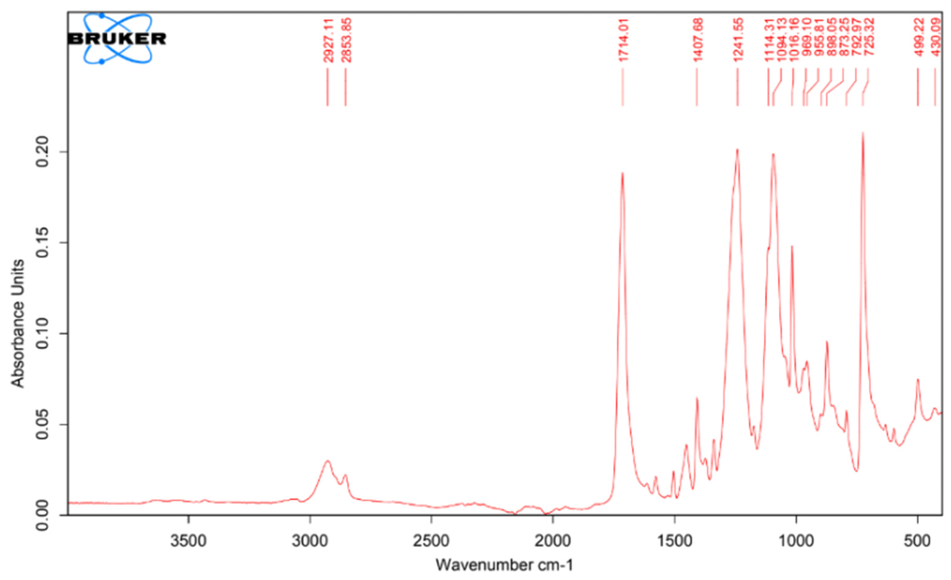
3.1.3. Fourier-Transform Infrared Spectrophotometry

The results showed that in the chemical structure of PETG, benzene, oxygen, and alcohol compounds can be identified in the 725.32, 1094.13–1241.55, and 1407.68 peaks respectively, as seen in Figure 4 [26].

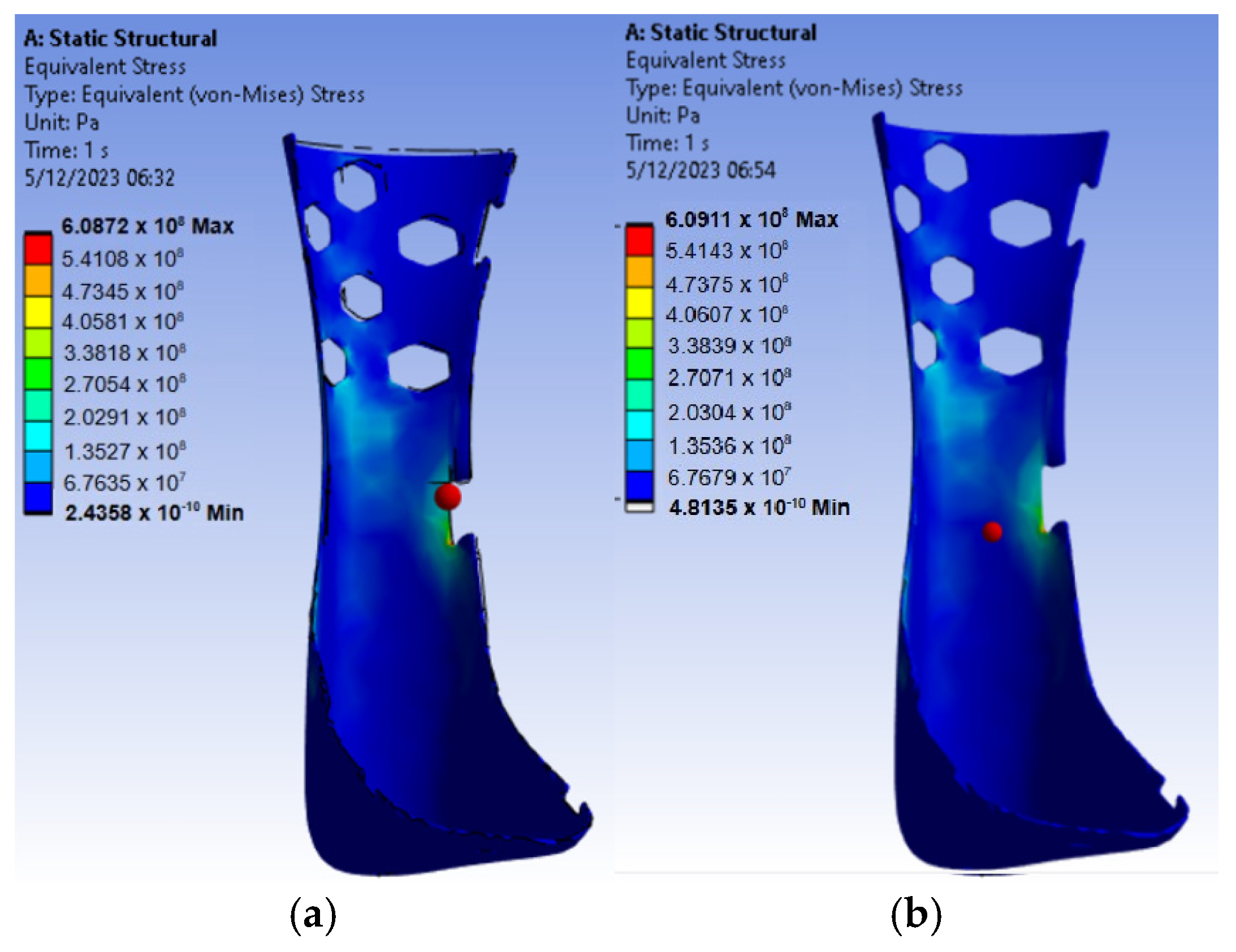
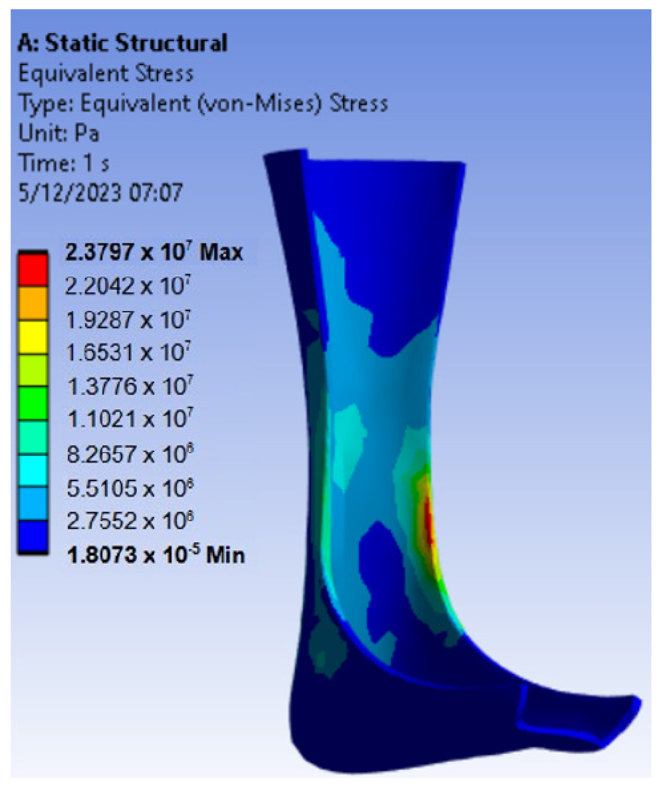
3.2. Mechanical Simulation

This part was performed to predict failure areas the physical situation considered was a person standing upright wearing an AFO. The objective here was to find out the stresses induced and the deflection of the AFO under static conditions. Since the person is standing, approximately half of their weight would be taken by each leg, and the acting force on the AFO will be the same. The weight of the person was taken as 70 kg, so a force of 350 N was applied to the AFO. And, the boundary condition consisted of imposing null deformation and displacement in the corresponding contact areas, in this case, all plantar faces. The analysis was carried out between PET, which is a material pre-defined on the software, and PETG, which was custom defined in order to assess its characteristics. Figure 5 shows the results.
As shown in Figure 6, PETG exhibits maximum strength values similar to those of PET, confirming its suitability as a material for orthosis design. Furthermore, it aids in identifying regions of maximum stress, which can guide further optimization processes. We also see that the maximum equivalent strength occurs at the boundary of the AFO. It should be noted that PET is not a printable material, which further justifies the choice of PETG.
For the first model, a lower maximum equivalent stress, in contrast with the final model, can be seen. Also, the minimum equivalent stress is quite higher than the final model, and the model’s maximum equivalent stress occurs at approximately the same point. As the minimum stress is dominant in all cases, the model that gives the minor minimum stress should be considered, which is the final model. This process validates the geometric changes and material selection.

3.3. Results of Mechanical Testing on 3D-Printed AFOs

The experiments showed that the first orthosis printed in the −15° position had a final value of 73 N without using the coupling and 60 N using the coupling. The second orthosis printed at −15° had a final value of 78 N using the coupling and 73 without using the coupling, the third orthosis at 0° gave a final value of 69 N using the coupling, and the last orthosis at −15° returned a final value of 70 N without using the coupling. The structure used for testing can be seen in Figure 7.
The orthosis printed at −15° has the highest final value without using the coupling (72.71 N). The orthosis printed at 0° has the lowest final value using the coupling (69.28 N). The use of the coupling appears to have a significant impact on the final values, with the values being lower when the coupling is used. This suggests that the coupling may not be necessary or may even be detrimental to the performance of the orthosis.

4. Conclusions

The proposed 3D-printed ankle–foot orthosis is a personalized device that has good potential to improve the functionality and quality of life of patients with problems in the lower limb region. The results of the structural tests were satisfactory, with a high tensile strength. However, mechanical testing revealed that its sole is too thin and can break under the application of excessive load. Therefore, it is necessary to increase the thickness of the foot sole to improve its resistance, as it was found that this was where the fault condition happened. Overall, the proposed AFO is a promising design that has the potential to be an effective alternative to conventional orthoses. However, more studies are needed to evaluate its clinical effectiveness and its impact on the quality of life of the patient. Additionally, modifications on the base of the AFO and additional mechanical testing are recommended since this would allow for better mechanical properties for the device.

Author Contributions

All authors contributed equally to this research. All authors have read and agreed to the published version of the manuscript.

Funding

This research received no external funding.

Institutional Review Board Statement

Not applicable.

Informed Consent Statement

Not applicable.

Data Availability Statement

Data are contained within the article.

Acknowledgments

The authors would like to thank Core Facilities—FABCORE from Pontificia Universidad Católica del Perú.

Conflicts of Interest

The authors declare no conflicts of interest.

References

  1. Catalán, E.; Sierra, M.; Ceballos, J.; Rendón, M. Tratamiento de esguince de tobillo grado II en adultos laboralmente activos: Inmovilización contra vendaje funcional. Rev. De Sanid. Mil. 2018, 72, 240–245. [Google Scholar]
  2. Esguince de Tobillo—Mayo Clinic. Available online: https://www.mayoclinic.org/es/diseases-conditions/sprained-ankle/symptoms-causes/syc-20353225 (accessed on 14 September 2023).
  3. Rincón Cardozo, D.F.; Camacho Casas, J.A.; Sauza Rodríguez, N.; Rincón Cardozo, P.A. Abordaje del esguince de tobillo para el médico general. Rev. De La Univ. Ind. De Santander 2015, 47, 85–92. [Google Scholar]
  4. Tratamiento con Cirugía en el Esguince de Tobillo—Cirugía Pie y Tobillo por Dr. Ballester. Available online: https://www.cirugiapie.com/blog/cirugia-en-esguince-de-tobillo (accessed on 15 September 2023).
  5. Pérez-Caballer, A.J.; Sanz-Hospital, J.; Delgado, P. Tratamiento quirúrgico de la inestabilidad lateral crónica de tobillo. Rev. Española De Cirugía Ortopédica Y Traumatol. 2004, 48, 53–59. [Google Scholar]
  6. Castillo Gonzalez, S.A.; Pulido Talero, W.E.; Castañeda Jerez, C.E. Diseño e impresión 3D de órtesis para tratamiento de ligamento cruzado posterior/anterior como herramienta de aplicación en la industria 4.0. Av. Investig. En Ing. 2022, 19, 27–43. [Google Scholar] [CrossRef]
  7. Lin, Y.-C.; Huang, L.-Y.; Chen, C.-S. Strength Evaluation and Modification of a 3D Printed Anterior Ankle Foot Orthoses. Appl. Sci. 2020, 10, 7289. [Google Scholar] [CrossRef]
  8. Cha, Y.H.; Lee, K.H.; Ryu, H.J.; Joo, I.W.; Seo, A.; Kim, D.-H.; Kim, S.J. Ankle-Foot Orthosis Made by 3D Printing Technique and Automated Design Software. Appl. Bionics Biomech. 2017, 2017, 9610468. [Google Scholar] [CrossRef] [PubMed]
  9. Del Maso, A.; Cosmi, F. 3D-printed ankle-foot orthosis: A design method. Mater. Today Proc. 2019, 12, 252–261. [Google Scholar] [CrossRef]
  10. Lukaszewski, K.; Raj, R.; Karwasz, A. Mechanical Evaluation of PET-G 3D-Printed Wrist-Hand Orthosis: An Integrated Experimental and Numerical Approach. Materials 2023, 16, 6132. [Google Scholar] [CrossRef] [PubMed]
  11. Batista, M.; Lagomazzini, J.M.; Ramirez-Peña, M.; Vazquez-Martinez, J.M. Mechanical and Tribological Performance of Carbon Fiber-Reinforced PETG for FFF Applications. Appl. Sci. 2023, 13, 12701. [Google Scholar] [CrossRef]
  12. Máquina de Ensayos Universal ProLine. Available online: https://www.zwickroell.com/es/productos/maquinas-de-ensayos-de-materiales-estaticas/maquinas-de-ensayos-universales-para-aplicaciones-estaticas/proline/ (accessed on 12 October 2023).
  13. Doronin, F.; Rudakova, A.; Rytikov, G.; Nazarov, V. Simple Determination of the Melt Flow Index of Composite Polymer Filaments Used in Material Extrusion Additive Manufacturing. Coatings 2023, 13, 1592. [Google Scholar] [CrossRef]
  14. “Medidor del índice de fluidez Mflow”, ZwickRoell. Available online: https://www.zwickroell.com/es/productos/medidores-del-indice-de-fluidez/medidor-del-indice-de-fluidez-mflow/ (accessed on 18 October 2023).
  15. Latko-Durałek, P.; Dydek, K.; Boczkowska, A. Thermal, Rheological and Mechanical Properties of PETG/rPETG Blends. J. Polym. Environ. 2019, 27, 2600–2606. [Google Scholar] [CrossRef]
  16. “Espectrómetros FT-IR de Rutina”, Bruker. Available online: https://www.bruker.com/es/products-and-solutions/infrared-and-raman/ft-ir-routine-spectrometer.html (accessed on 8 November 2023).
  17. Sense Scanner. Available online: https://support.3dsystems.com/s/article/Sense-Scanner?language=en_US (accessed on 8 November 2023).
  18. Meshmixer. Available online: https://meshmixer.com/ (accessed on 15 November 2023).
  19. Peirone, M. Using Fusion 360 to Design Patient-Specific Prosthetic and Orthotic Devices. Autodesk. Available online: https://static.au-uw2-prd.autodesk.com/Class_Handout_SD500053_ClassHandout-SD500053-Peirone-AU2021.pdf (accessed on 15 November 2023).
  20. Song, P.; Qi, Y.M.; Cai, D.C. Research and Application of Autodesk Fusion 360 in Industrial Design. IOP Conf. Ser. Mater. Sci. Eng. 2018, 359, 012037. [Google Scholar] [CrossRef]
  21. Ultimaker Cura. Available online: https://ultimaker.com/software/ultimaker-cura/ (accessed on 5 December 2023).
  22. Filamento para Impresión 3d en PET-G Azul. Available online: https://bimek3d.com/filamentos-para-impresion-3d/pet-g/filamento-para-impresi%C3%B3n-3d-en-pet-g-azul-detail (accessed on 5 December 2023).
  23. Ielapi, A.; Forward, M.; De Beule, M. Computational and Experimental Evaluation of the Mechanical Properties of Ankle Foot Orthoses: A Literature Review. Prosthet. Orthot. Int. 2019, 43, 339–348. [Google Scholar] [CrossRef] [PubMed]
  24. Raj, R.; Dixit, A.R.; Łukaszewski, K.; Wichniarek, R.; Rybarczyk, J.; Kuczko, W.; Górski, F. Numerical and Experimental Mechanical Analysis of Additively Manufactured Ankle–Foot Orthoses. Materials 2022, 15, 6130. [Google Scholar] [CrossRef] [PubMed]
  25. Mansilla, P. Análisis de los Parámetros del Proceso de Impresión 3D FGF. Aplicación a la Fabricación de Mobiliario; Universidad de Valladolid: Valladolid, Spain, 2023. [Google Scholar]
  26. “Tablas de Espectroscopía”, Universidad de Granada. Available online: https://www.ugr.es/~quiored/lab/tablas_espec/ir.htm (accessed on 5 December 2023).
Figure 1. The manufacturing process of the previously described AFO. (a) Scanning process on a volunteer. (b) Initial and (c) final result of Autodesk Meshmixer edition. (d) First model of the AFO in Autodesk Fusion 360. (e) Modeling of the AFO in Ultimaker Cura. (f) Finalized prototype, with cloth and straps added.
Engproc 83 00024 g001
Figure 2. Three-dimensional-printed AFOs.
Engproc 83 00024 g002
Figure 3. Three-dimensional AFO models converted to solid format, which is a format suitable for carrying out the FE simulations. (a) First model. (b) Final model.
Engproc 83 00024 g003
Figure 4. Spectrum of the PETG filament.
Engproc 83 00024 g004
Figure 5. FE simulation results for the final model, the AFO. (a) PETG. (b) PET.
Engproc 83 00024 g005
Figure 6. FE simulation results for the first model (PETG).
Engproc 83 00024 g006
Figure 7. An AFO before (a) and undergoing (b) mechanical testing. Note that the coupling was not used for this AFO.
Engproc 83 00024 g007
Table 1. Three-dimensional printing protocols for the AFO.
ParameterValueObservations
Angle with respect to the base−15°-
Layer height0.28 mm-
Line width0.44 mm-
Wall thickness1.76 mm4 wall lines
Horizontal expansion1 mm-
Top layers4-
Bottom layers3-
Infill density15%Gyroid pattern
Printing temperature240 °CAccording to the literature, an optimal temperature ranges from 230 °C to 250 °C [22]
Print speed65 m/s
Support density6%Zig Zag Pattern
Adhesion typeBrim
Conical supportEnabled30° support angle and 5 mm minimum width
Table 2. Mechanical characteristics of materials used in FE simulations.
MaterialDensity (kg/m3)Young’s Modulus (MPa)Poisson CoefficientTensile Yield Strength (MPa)
PET133928980.3852.4
PETG12702035.810.3551.4
Disclaimer/Publisher’s Note: The statements, opinions and data contained in all publications are solely those of the individual author(s) and contributor(s) and not of MDPI and/or the editor(s). MDPI and/or the editor(s) disclaim responsibility for any injury to people or property resulting from any ideas, methods, instructions or products referred to in the content.

