Proceeding Paper

Development and Implementation of Modular Turning Dynamometer with Miniature Load Cell †

Department of Teacher Training in Mechanical Engineering, Faculty of Technical Education, King Mongkut’s University of Technology North Bangkok, Bangkok 10800, Thailand
*
Author to whom correspondence should be addressed.
Presented at the 8th Mechanical Engineering, Science and Technology International Conference, Padang Besar, Perlis, Malaysia, 11–12 December 2024.
Eng. Proc. 2025, 84(1), 43; https://doi.org/10.3390/engproc2025084043
Published: 7 February 2025

Abstract

:
This study presents the design, development, and implementation of a novel modular three-axis cutting force measurement system for turning lathes. The system employs miniature load cells in an innovative two-channel slotted dynamometer structure, offering a cost-effective and compact alternative to conventional dynamometers. The primary structure utilizes a cantilever concept, in which cutting forces induce deformation, compressing strategically positioned load cells. A 300 kgf load cell measures the main cutting force, while a 100 kgf load cell detects the feed force. Additionally, a 20 kgf load cell measures the radial force through a sliding tool holder mechanism. Finite element analysis was employed to optimize the dynamometer’s parameters, striking a balance between maximum deflection and structural integrity. The optimized design achieved a safety factor of 4.377, with maximum deflections of 8.81 µm and 9.89 µm for the main cutting and feed force measurements, respectively. Static calibration of the load cells demonstrated robust correlations between voltage and force, with the coefficient of determination (R2) values exceeding 0.999. The system’s precision was evaluated through cutting experiments on mild steel of varying depths (0.5, 0.75, 1.0 mm) and feed rates (0.105, 0.150, 0.210 mm/rev). The experimental results indicate that the main cutting force consistently exceeded feed and radial forces across all conditions. The system exhibited high precision, with relative standard deviation (RSD) percentages below 5% on average and not exceeding 7.5% in individual experiments. This modular dynamometer design offers a flexible, precise, and cost-effective solution for cutting force measurement in turning operations. Its modularity facilitates easy maintenance and adaptation to various cutting conditions, rendering the developed modular turning dynamometer suitable for both research and industrial applications.

1. Introduction

Measuring cutting forces accurately during turning operations is crucial for monitoring tool wear, optimizing cutting parameters, and ensuring machining quality [1]. Several researchers have reported different approaches to developing cutting force measurement systems for lathes [2,3]. Various approaches have been proposed for measuring cutting forces in turning lathe processes by applying piezoelectric crystals, strain gauges, and semiconductor strain gauges [3,4,5]. These sensors provide a compact and cost-effective solution directly mounted on the tool shank, minimizing signal amplification and distortion [6]. Researchers have developed dynamometers and smart tool holders integrated with highly sensitive sensors to accurately measure cutting forces, including the main cutting force (Fc), feed force (Ff), and radial force (Fr), which act on the cutting tool tip and correspond to forces in the coordinate system (Fx, Fy, Fz). Traditional methods of cutting force measurement often depend on complex and expensive dynamometers that are installed into the machine tool, limiting their applicability and flexibility [7,8].
The displacement sensor dynamometer can detect the cutting force by deflecting part of the main structure of the dynamometer [9]. The deflection during the turning process affects the vibration of the cutting tool and results in a wavy surface on the finished work piece [10,11]. The strain gauge and piezoelectric sensors are sensitive to the high temperature during the cutting process between the tool tip and the work piece [4,12]. These sensors are not resistant to the cooling system during the cutting process. The miniature load cell is a smaller version of the commercial load sensor and sealed with metal to protect against ambient disturbance inside the sensor [9,13]. Another approach to cutting force measurement is the use of miniature load cells. Like thin-film piezoelectric sensors, load cells can be integrated directly onto the cutting tool, providing a modular design [7,14]. The modular design of cutting force measurement systems using miniature load cells offers several advantages [15]. First, the compact size of the load cells allows for simplified installation on the cutting tool without significantly altering the tool’s geometry [2]. Second, the modular nature of the design allows for the replacement of individual load cells, simplifying maintenance and repair [9]. Furthermore, the utilization of multiple load cells can enable the measurement of cutting forces in three axes, providing a more comprehensive understanding of the cutting process [7,16].
By employing a modular design with miniature load cells, researchers can develop cutting force measurement systems that are cost-effective, compact, and easily installed into existing machine tools. This study aims to develop and implement a three-axis cutting forces measurement system for a turning lathe. The modular design of the proposed system will also facilitate the integration of advanced data acquisition and analysis capabilities, enabling comprehensive studies of the cutting process and the optimization of machining operations.

2. Materials and Methods

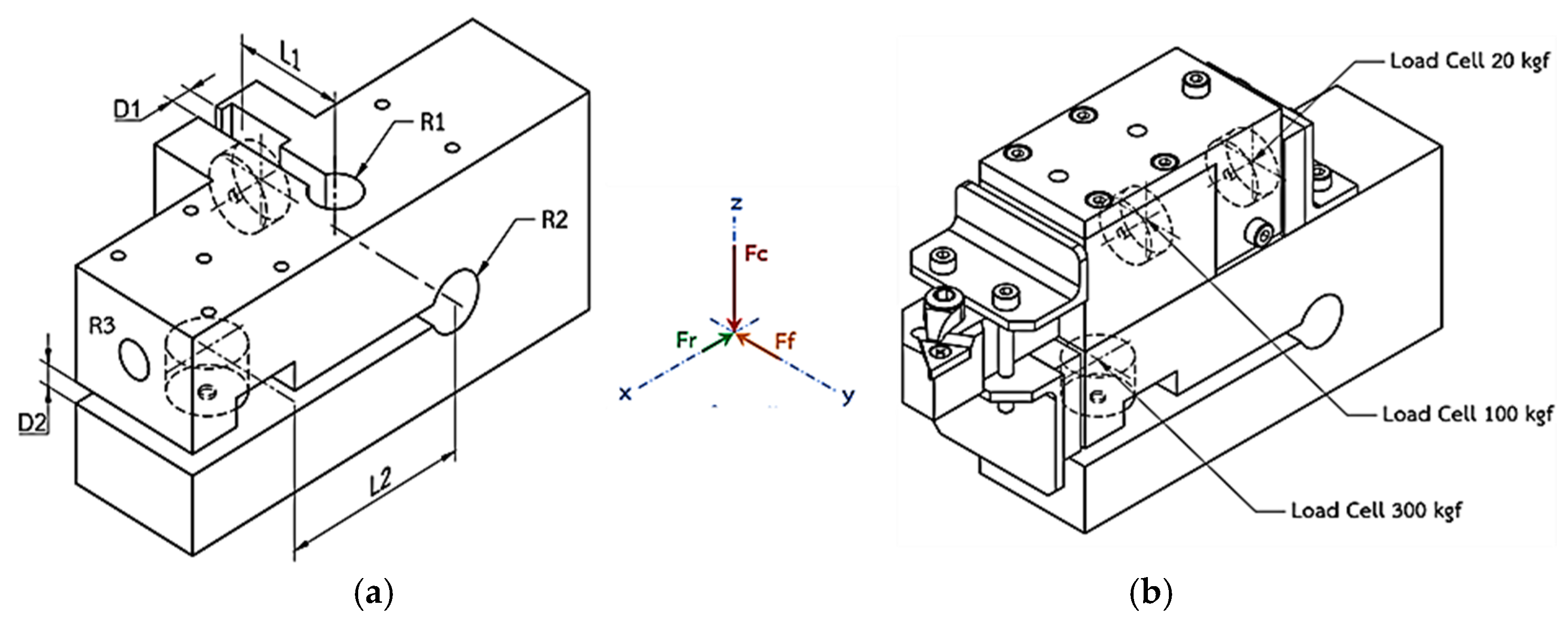
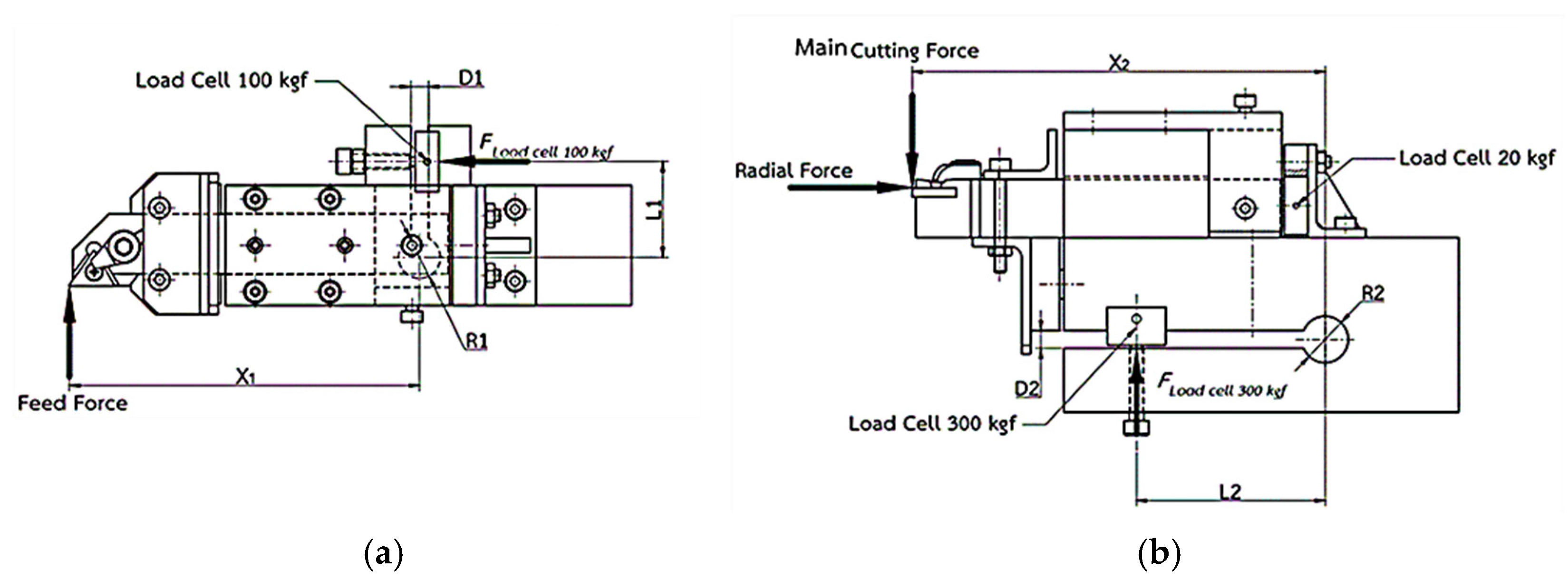
2.1. Main Concept for Modular Turning Dynamometer Design

The cutting forces are indirectly measured by applying dynamometer structure deformation based on material properties, especially the modulus of elasticity. Therefore, the measurement deflection of the dynamometer structure by using a displacement sensor for direct measurement and strain gauges equipped on cutting tool holder is based on the displacement ratio of a cantilever. This study applied a slotted cantilever concept due to the advantage of deformation behavior acting as the compression in specific positions. The two-channel slots named D1 and D2 in Figure 1a were designed for this purpose [17,18]. The drilled holes R1 and R2 on the dynamometer structure are shown in Figure 1a; the moment around the center of the holes led to the bending moment of the cantilever. The miniature load cells were installed at positions L1 and L2 to detect the compression of the cantilever for measuring the feed force (Ff) and the main cutting force (Fc), respectively. To measure the radial force (Fr), the hole R3 was drilled to act as a guide brush and a clamping set for the tool holder which slides along the guide brush to press the load cell with a force of 20 kgf against the back of the tool holder, as shown in Figure 1b. Miniature load cells of 300, 100, and 20 kgf were employed to detect the compression force of the main cutting force (Fc), feed force (Ff), and radial force (Fr), respectively.
The drawing in Figure 2a,b shows the top and front view of the assembled dynamometer and cutting tool installation. In Figure 2, the feed and main cutting force were calculated from a set of measurements of the miniature load cell forces (load cell 300 kgf, 100 kgf) multiplied by the distance from the center of the hole to the installed load cell position (L1, L2) and then divided by the distance from the center of the hole to the cutting force at the cutting tool tip (X1, X2). However, the radial cutting force was measured by sliding the cutting tool holder on the dynamometer guide and directly pressing it against the load cell of 20 kgf.

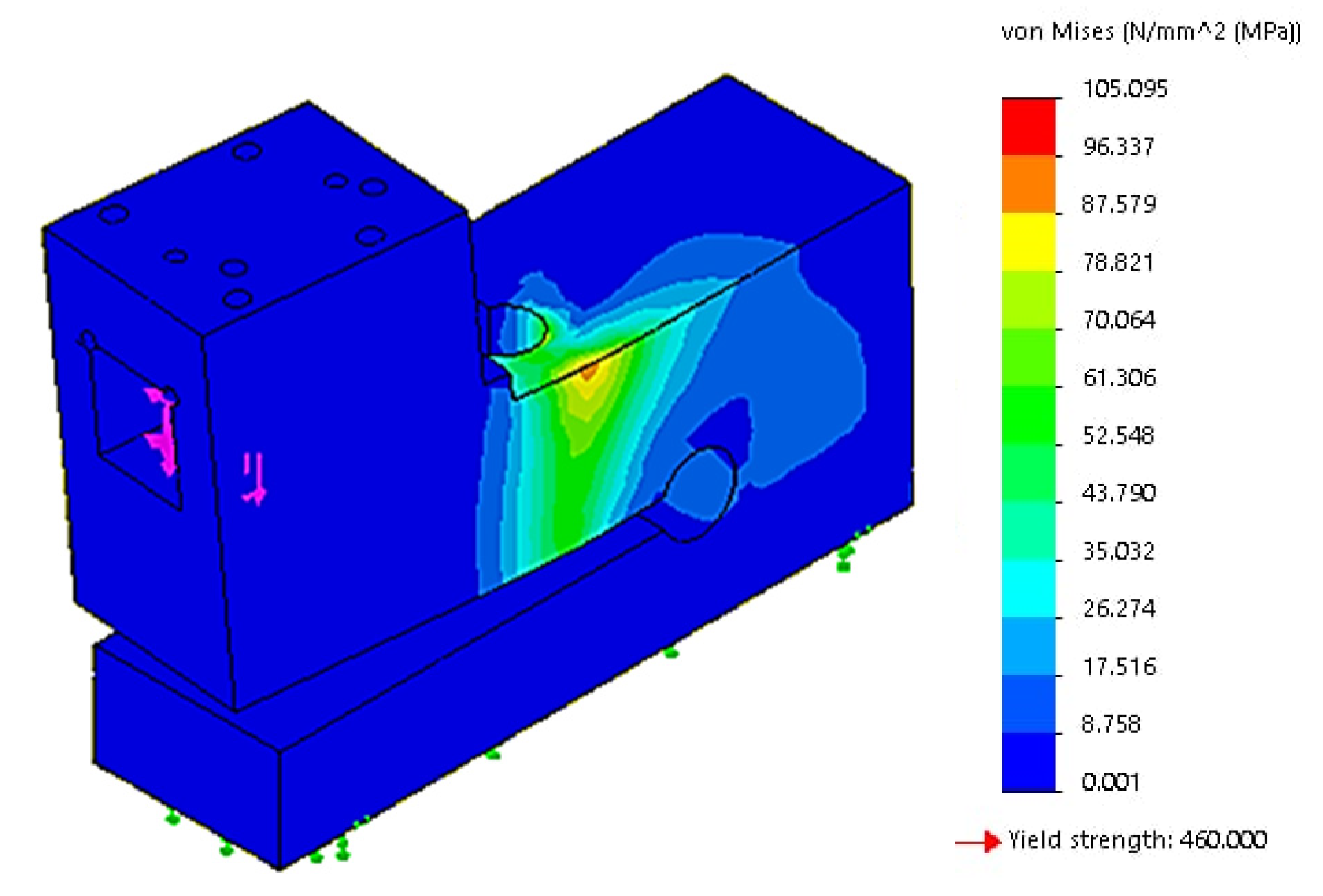
2.2. Finite Element Analysis for Dynamometer Parameter Optimization

As mentioned above, regarding the dynamometer design concept, the drill holes R1 and R2 were significant factors in the determining the response to a cutting force, while the lengths L1 and L2 were important parameters determining the moment applied to the miniature load cells. Therefore, finite element simulation for analyzing maximum deflection and minimum von Mises stress must be carefully considered to ensure the reactivity and integrity of the dynamometer. The significant parameters, including R1, L1, R2, and L2, were evaluated at four levels and we performed a simulation with the factorial experimental design. Parameters R1 and R2 consisted of 4, 5, 6, 7, and 8 mm. L1 utilized values of 32, 30, 28, 26, and 24 mm., while L2 employed values of 70, 68, 66, 64, and 62 mm. The dynamometer was made from SN490C advanced high-strength steel with a yield strength of 460 MPa. The 300, 100, and 20 kgf load cells were applied as the load for the simulation to find the optimal values of R1, R2, L1, and L2.

2.3. Measuring System Configuration and Display Software

Each miniature load cell was connected to a universal signal conditioner and the amplified signal was transmitted to the Arduino UNO R3, as shown in the hardware side of Figure 3. The language graphic program was used for programing to receive the signal from the microcontroller board Arduino UNO R3 and show each cutting force on the screen, as illustrated in the software side of Figure 3. The calibration testing from the compression machine examined the correlation of the compression force and output voltage in the range 0–5 VDC to establish the calibration curve. The calibration of the miniature load cells of 300, 100, and 20 kgf was performed on the universal testing machine by applying the compression load after the maximum load of each load cell. The calibration and moment equations were embedded in the computation method of the cutting force software, as represented in the software side of Figure 3.

2.4. Experimentation and Precision Analysis

Cutting experiments were performed on a semiauto lathe, model AFM TUG-40 (machine manufacturer AFM, Dolnośląskie, Poland). A cutting tool tip, CNMG 12 04 08-WMX 4225 (Sandvik Coromant, Sandviken, Sweden), was used in the experiment and mounted on a TaeguTec (Daegu, Republic of Korea) PCLNR 2020 K12 tool holder. Mild steel with a diameter of 38 mm was selected for cutting under turning conditions that included headstock revolution, depth of cut, and feed rate. A headstock revolution of 710 rpm was determined to achieve a cutting speed of approximately 83.6 m/min. Three levels of depth of cut, 0.5, 0.75, and 1 mm, were used for the experiments. The feed rate also varied across three levels including 0.105, 0.150, and 0.210 mm/rev with 3 replications.
The accuracy of measurement was evaluated by the percentage of the relative standard deviation (RSD) with respect to the established acceptance criteria for instrument calibration. The RSD is a statistical measure that provides information about the variability in a set of measurements, with lower values indicating higher precision. The RSD is a percentage of the standard deviation divided by the mean observation value. RSD values ranging from 5 to 10% may be considered acceptable, contingent upon the sample’ matrix’s complexity and the analytical method’s specific requirements [19,20].

3. Design and Implementation Results

3.1. Dynamometer Parameter Optimization

Table 1 shows the optimum results of the finite element analysis for the determination of the dynamometer parameters including R1, R2, L1, and L2. The maximum deflection of L1 and L2 was 8.81 and 9.89 µm, respectively. These results correspond to the set of dynamometer parameters R1, R2, L1, and L2 which were 7, 8, 32, and 70 mm, respectively. Considering the maximum von Mises stress, these parameters resulted in 105.095 MPa with a safety factor of 4.377. Figure 4 shows a simulation example of the maximum von Mises stress 105.095 MPa behind hole R1. This safety factor was lower than the design parameters from rows 1–3 in Table 1. However, the result reveals a deflection value more than 1.7 times greater based on the other deflection values. To apply an effective compression force on the miniature load cell, the maximum deflection was the main consideration rather than the strength of the dynamometer. Additionally, a safety factor exceeding four was considered sufficient for ensuring safety.

3.2. Modular Turning Dynamometer Design

The fabricated dynamometer and the completed set of measured cutting forces are shown in Figure 5a,b. The main parts consist of eight components: 1. the main structure of the dynamometer; 2. the tool holder sliding guide; 3. the load cell of 20 kgf for measuring the radial force (Fr); 4. the load cell of 100 kgf for measuring the feed force (Ff); 5. the load cell of 300 kgf for measuring the main cutting force (Fc); 6. the tool holder sliding set; 7. the cover plate for clamping the tool holder; and 8. the cutting tool tip. The tool holder sliding guide was specifically designed with a transition tolerance fit to enable the tool holder to slide freely along the slotted guide and apply compression force to a 20 kgf load cell. Three load cells were installed in a load cell holder location. A small screw was mounted for clamping and adjusting the pre-load acting on each load cell. The complete set of measured cutting forces is presented in Figure 5b and includes four components. Component A is a modular dynamometer. The three universal signal conditions were installed in the cooling box as component B. The microcontroller component C was used as an interface to change the analog signal to a digital signal. The developed display software was installed on the computer as component D to show the real-time measured cutting force on each axis.

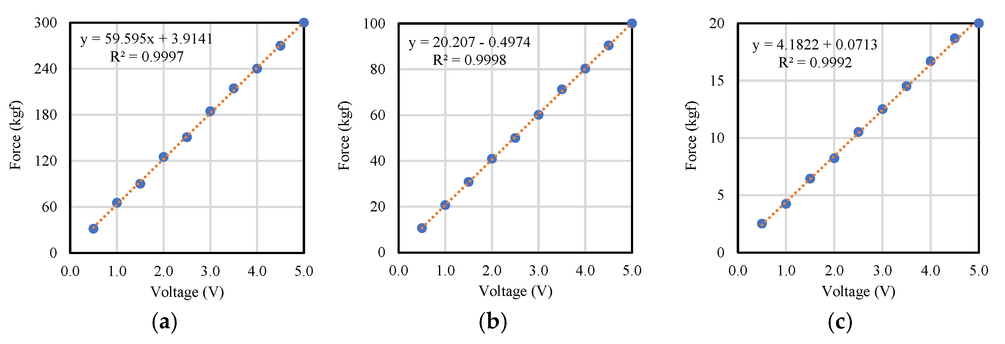
3.3. Static Calibration of Miniature Load Cell

Calibration curves were created to enable the conversion of the input measuring voltage to the output force. Figure 6a–c represent the signal obtained from the calibration curves of the 300 kgf, 100 kgf, and 20 kgf load cells, respectively. Each load cell showed a strong correlation of voltage and force, with R2 values of 0.9997, 0.9998, and 0.9992 for the 300 kgf, 100 kgf, and 20 kgf load cells, respectively. As a result, the linear equations from the calibration curves are shown in the software program.

3.4. Implementation and Precision Analysis

Figure 7, Figure 8 and Figure 9 show the cutting force under the turning conditions at three levels of depth of cut and feed rate. All cutting experiments demonstrated that the main cutting force was higher than the feed and radial force. The radial force had the lowest level of cutting force compared with the other two cutting forces. Each cutting force was increased by increasing the feed rate and depth of cut. The precision of the dynamometer was analyzed in terms of the percentage RSD of each experiment. The maximum 7.5% RSD was observed for the radial force (Fr) at a feed rate of 0.75 mm/rev. The individual percentage of the RSD was lower than 10%. The gross mean of the maximum values of the RSD for Fc, Ff, and Fr which were obtained at a depth of cut of 0.5 mm were 4.66%, 4.20%, and 4.73%, respectively. The percentage RSD obtained was less than 5%. Therefore, a modular dynamometer was successfully designed and developed using miniature load cells with a high precision of measurement and can be used on the shop floor to monitor cutting force.

4. Conclusions

A turning dynamometer was designed and developed which incorporates a two-channel slotted concept within its main structure. The cutting force applied to the tool tip induced deformation in the unslotted portion of the main structure, causing it to behave as a cantilever. This cantilever deflection compressed the miniature load cells which measured the primary cutting and feed forces, utilizing 300 kgf and 100 kgf capacity load cells, respectively. The radial force was determined by the tool holder’s sliding motion, which compressed the 20 kgf load cell. The constructed dynamometer exhibited a low percentage RSD, not exceeding 5% on average and 7.5% for individual cutting experiments. This study demonstrates the potential of alternating the load capacity of a miniature load cell based on material type and cutting parameters, leading to a modular load turning dynamometer.

Author Contributions

Conceptualization, B.S. and N.K.; methodology, P.N.; software, P.N. and C.P., validation, B.S. and N.K.; formal analysis, P.N.; investigation, C.P.; resources, B.S.; data curation, B.S.; writing—original draft preparation, B.S. and C.P.; writing—review and editing, B.S.; visualization, C.P.; supervision, B.S. and N.K.; project administration, N.K.; funding acquisition, B.S. All authors have read and agreed to the published version of the manuscript.

Funding

The authors gratefully acknowledge funding provided by King Mongkut’s University of Technology North Bangkok under grant no. KMUTNB-64-DRIVE-37.

Institutional Review Board Statement

Not applicable.

Informed Consent Statement

Not applicable.

Data Availability Statement

The datasets featured in this article are not currently available for public access as they are part of an ongoing research project. Any requests to access these datasets should be sent to the corresponding author.

Acknowledgments

The authors wish to express their sincere gratitude for the invaluable support provided.

Conflicts of Interest

The authors declare no conflicts of interest.

References

  1. Sredanović, B.; Carou, D. Monitoring of Cutting Forces in Turning. In Notes for Manufacturing Instructors; Carou, D., Davim, J.P., Eds.; Springer: Cham, Switzerland, 2024; pp. 131–149. [Google Scholar]
  2. Zhang, J.; Xiao, G.; Yi, M.; Chen, Z.; Wang, L.; Chen, J.; Xu, C. Accurate Cutting-Force Measurement with Smart Tool Holder in Lathe. Sensors 2023, 23, 4419. [Google Scholar] [CrossRef] [PubMed]
  3. Kumar, P.; Yadav, S. Measurement and Analysis of Cutting Forces Using Dynamometer in Turning of EN-8 Steel. Mater. Today Proc. 2023, in press. [Google Scholar] [CrossRef]
  4. Panesso, M.; Ettrichrätz, M.; Gebhardt, S.; Georgi, O.; Rüger, C.; Gnauck, M.; Drossel, W.G. Design and Characterization of Piezoceramic Thick Film Sensor for Measuring Cutting Forces in Turning Processes. In Manufacturing Driving Circular Economy: GCSM 2022; Kohl, H., Seliger, G., Dietrich, F., Eds.; Lecture Notes in Mechanical Engineering; Springer: Cham, Switzerland, 2023; pp. 30–39. [Google Scholar]
  5. Yu Timokhin, I.; Anashkina, A.A.; Kharakhonov, G.A.; Ermolaev, Y.O. Cutting Force Measurement During Machining of the Ceramic Parts Designed for Aviation Purposes. Proc. High. Educ. Inst. Machine Build. 2023, 6, 47–57. [Google Scholar] [CrossRef]
  6. Uquillas, D.A.R.; Yeh, S.S. Tool Holder Sensor Design for Measuring the Cutting Force in CNC Turning Machines. In Proceedings of the 2015 IEEE International Conference on Advanced Intelligent Mechatronics (AIM), Busan, Republic of Korea, 7–11 July 2015; pp. 1218–1223. [Google Scholar]
  7. Totis, G.; Bortoluzzi, D.; Sortino, M. Development of A Universal, Machine Tool Independent Dynamometer for Accurate Cutting Force Estimation in Milling. Int. J. Mach. Tools Manuf. 2024, 198, 104–151. [Google Scholar] [CrossRef]
  8. Rizal, M.S.; Ghani, J.A.; Usman, H.; Dirhamsyah, M.; Mubarak, A.Z. Development and Testing of a Stationary Dynamometer Using Cross-beam-Type Force-Sensing Elements for Three-Axis Cutting Force Measurement in Milling Operations. Proc. Inst. Mech. Eng. Part B J. Eng. Manuf. 2023, 238, 950–961. [Google Scholar] [CrossRef]
  9. Mohanraj, T.; Irfan, M.; Uddin, S.K. Review on Sensor Design for Cutting Force Measurement. Proc. Inst. Mech. Eng. Part E J. Process Mech. Eng. 2022, 327, 1–12. [Google Scholar] [CrossRef]
  10. Khatekar, N.V.; Kalidasan, R.; Pawade, S.R. An FEM-ANN Based Analysis of Cutting Force and Cutting Tool Deflection to Predict Tool Wear in Double Tool Turning Process. Key Eng. Mater. 2023, 959, 67–76. [Google Scholar] [CrossRef]
  11. Ho, Q.N.; Do, T.T.; Minh, P.S. Studying the Factors Affecting Tool Vibration and Surface Quality during Turning through 3D Cutting Simulation and Machine Learning Model. Micromachines 2023, 14, 1025. [Google Scholar] [CrossRef] [PubMed]
  12. Li, X.; Ren, Z.; Zhang, J.; Li, W.; Jia, Z.; Qian, M. Development of a Shear-Type Dynamometer for High-Temperature Environment. IEEE Sens. J. 2022, 22, 15893–15902. [Google Scholar] [CrossRef]
  13. Gong, T.; Zhao, Y.; Zhao, Y.; Wang, L.; Yang, Y.; Ren, W. Design and Manufacturing of a High-Sensitivity Cutting Force Sensor Based on AlSiCO Ceramic. Micromachines 2021, 12, 63. [Google Scholar] [CrossRef] [PubMed]
  14. Song, X.; Wu, W.J.; Zhao, Y.; Cheng, Y.P.; Liu, L. Structural Design and Optimization of the Milling Force Measurement Tool System Embedded with Thin-Film Strain Sensors. Micromachines 2023, 14, 2133. [Google Scholar] [CrossRef] [PubMed]
  15. Apichatbanlue, U.; Suksawat, B. Data Acquisition System for Main Cutting Force Measurement in Turning Operation. In Proceedings of the 2011 11th International Conference on Control, Automation and Systems, Gyeonggi-do, Republic of Korea, 26–29 October 2011; pp. 1003–1005. [Google Scholar]
  16. Liu, Y.; Chen, C.; Li, F.Z.; Zhang, Y.; Ju, B.F.; Lin, H. Three-Axial Cutting Force Measurement in Micro/Nano-Cutting by Utilizing a Fast Tool Servo with A Smart Tool Holder. CIRP Ann. 2021, 70, 33–36. [Google Scholar]
  17. Youssef, H.; El-Hofy, H. Traditional Machining Technology, 2nd ed.; Deanta Global: Chennai, India, 2020. [Google Scholar]
  18. Boothroyd, G.; Knight, W.A. Fundamentals of Metal Machining and Machine Tools, 2nd ed.; McGraw-Hill: New York, NY, USA, 1989. [Google Scholar]
  19. Zhang, F.; Zhao, J.; Zhang, X. Estimation of Relative Standard Deviation Related to Limit of Detection and Limit of Quantitation. AHFE Int. 2023, 104, 36–40. [Google Scholar]
  20. Prasad, M.; Snyderman, N.J.; Verbeke, J. Analytical Error Bars and RSD for Neutron Multiplicity Counting. Nucl. Instrum. Methods Phys. Res. A 2018, 903, 25–31. [Google Scholar] [CrossRef]
Figure 1. (a) Main structure of dynamometer. (b) Installation of miniature load cells.
Engproc 84 00043 g001
Figure 2. (a) Top view of dynamometer. (b) Front view of dynamometer.
Engproc 84 00043 g002
Figure 3. Measuring system configuration and display software.
Engproc 84 00043 g003
Figure 4. Finite element analysis of Von Mises stress.
Engproc 84 00043 g004
Figure 5. (a) Fabrication dynamometer; (b) completed setup of dynamometer.
Engproc 84 00043 g005
Figure 6. (a) The 300 kgf load cell calibration curve; (b) the 100 kgf load cell calibration curve; (c) the 20 kgf load cell calibration curve.
Engproc 84 00043 g006
Figure 7. (a) Cutting force with depth of cut of 0.5 mm. (b) Percentage RSD with depth of cut of 0.5 mm.
Engproc 84 00043 g007
Figure 8. (a) Cutting force with depth of cut of 0.75 mm. (b) Percentage RSD with depth of cut of 0.75 mm.
Engproc 84 00043 g008
Figure 9. (a) Cutting force with depth of cut of 1.0 mm. (b) Percentage RSD with depth of cut of 1.0 mm.
Engproc 84 00043 g009
Table 1. Optimum dynamometer parameters.
No.R1 (mm)L1 (mm)Deflection 1 (µm)R2 (mm)L2 (mm)Deflection 2 (µm)Max. Von Mieses Stress (MPa)Safety
Factor
14324.588705.7586.1725.338
25325.238706.7085.3375.390
36326.558707.9695.1604.834
47328.818709.89105.0954.377
58328.008708.62121.7133.779
Disclaimer/Publisher’s Note: The statements, opinions and data contained in all publications are solely those of the individual author(s) and contributor(s) and not of MDPI and/or the editor(s). MDPI and/or the editor(s) disclaim responsibility for any injury to people or property resulting from any ideas, methods, instructions or products referred to in the content.

