
A Generalized Model to Describe Electromagnetic Shock Absorbers †


Abstract
1. Introduction
2. Materials and Methods
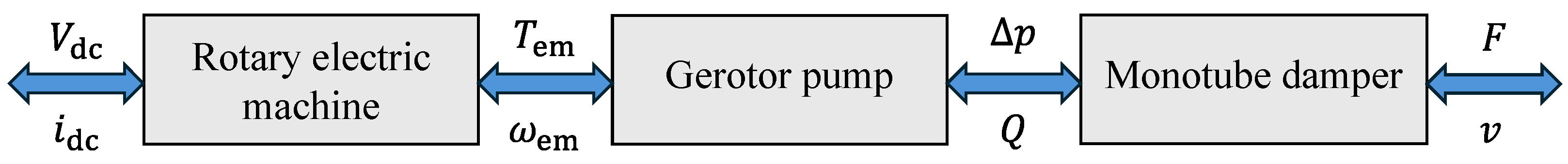
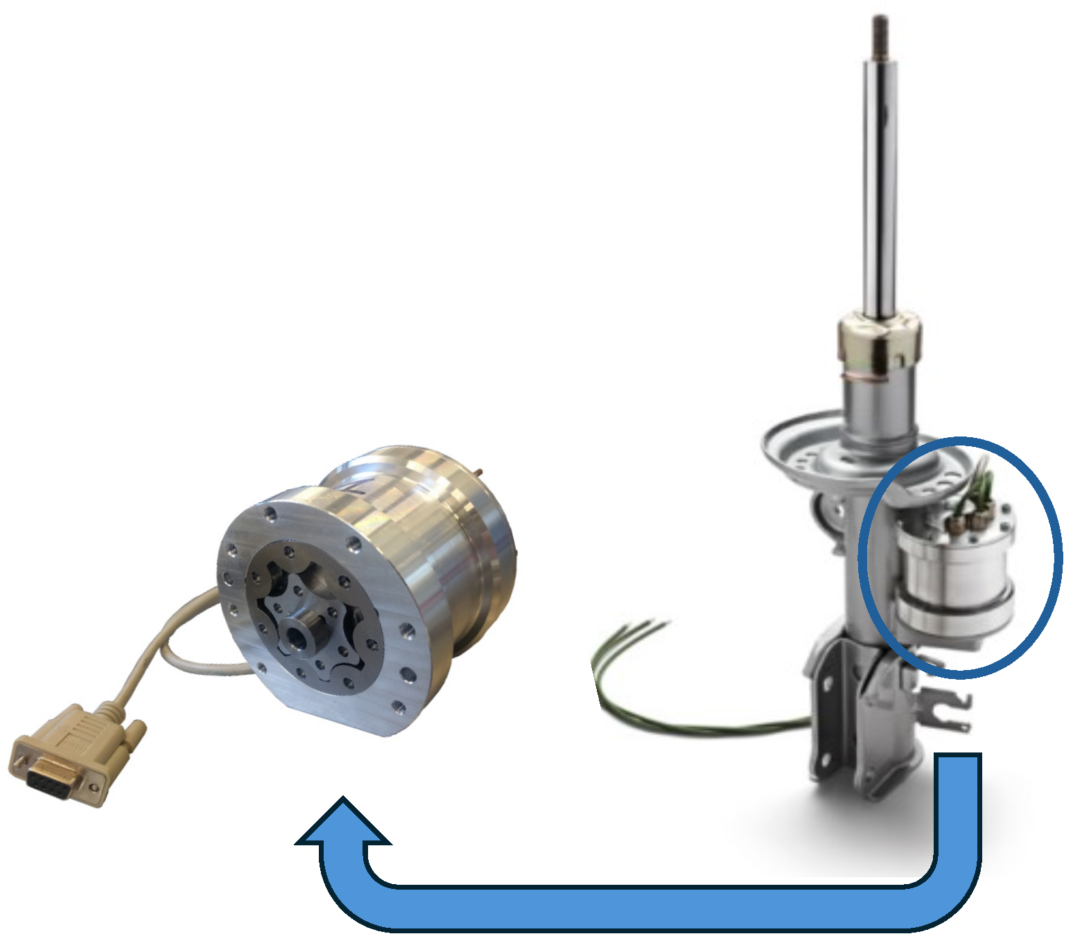
2.1. Electro-Hydrostatic Shock Absorber
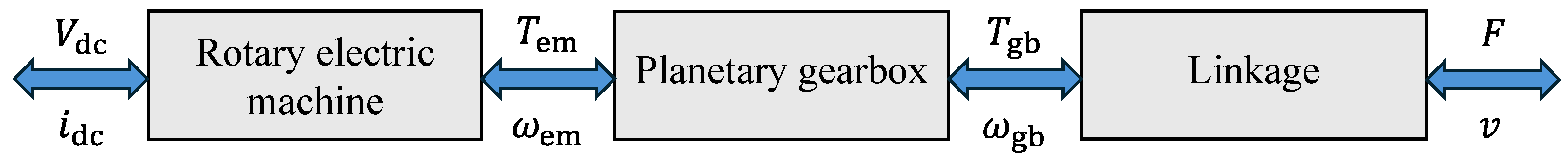
2.2. Electro-Mechanical Shock Absorber
2.3. Generalized Model
2.4. Simplified Model
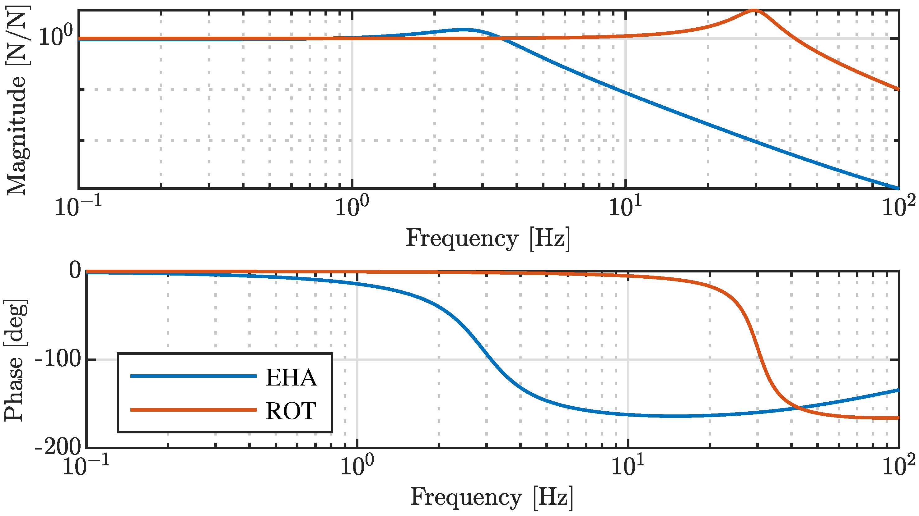
3. Results
3.1. Generalized Model
3.2. Simplified Model
3.3. Discussion
4. Conclusions
Author Contributions
Funding
Data Availability Statement
Acknowledgments
Conflicts of Interest
Abbreviations
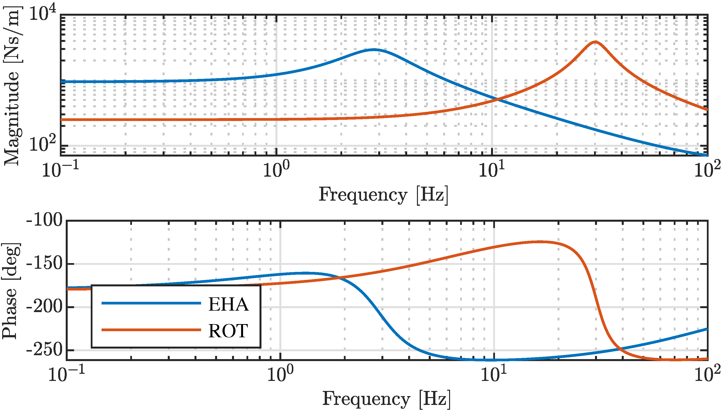
| EHA | Electro-Hydrostatically Actuated Shock Absorber |
| ROT | Rotary Electro-mechanical Shock Absorber |
| MISO | Multi Input Single Output |
| SISO | Single Input Single Output |
References
- Mazzilli, V.; De Pinto, S.; Pascali, L.; Contrino, M.; Bottiglione, F.; Mantriota, G.; Gruber, P.; Sorniotti, A. Integrated chassis control: Classification, analysis and future trends. Annu. Rev. Control 2021, 51, 172–205. [Google Scholar] [CrossRef]
- Yu, M.; Evangelou, S.A.; Dini, D. Advances in Active Suspension Systems for Road Vehicles. Engineering 2024, 33, 160–177. [Google Scholar] [CrossRef]
- Zuo, L.; Zhang, P.S. Energy harvesting, ride comfort, and road handling of regenerative vehicle suspensions. J. Vib. Acoust. 2013, 135, 011002. [Google Scholar] [CrossRef]
- Abdelkareem, M.A.; Xu, L.; Ali, M.K.A.; Elagouz, A.; Mi, J.; Guo, S.; Liu, Y.; Zuo, L. Vibration energy harvesting in automotive suspension system: A detailed review. Appl. Energy 2018, 229, 672–699. [Google Scholar] [CrossRef]
- Karnopp, D. Permanent magnet linear motors used as variable mechanical dampers for vehicle suspensions. Veh. Syst. Dyn. 1989, 18, 187–200. [Google Scholar] [CrossRef]
- Klimenko, Y.I.; Batishchev, D.; Pavlenko, A.; Grinchenkov, V. Design of a linear electromechanical actuator with an active vehicle suspension system. Russ. Electr. Eng. 2015, 86, 588–593. [Google Scholar] [CrossRef]
- Fang, Z.; Guo, X.; Xu, L.; Zhang, H. Experimental study of damping and energy regeneration characteristics of a hydraulic electromagnetic shock absorber. Adv. Mech. Eng. 2013, 5, 943528. [Google Scholar] [CrossRef]
- Liu, Y.; Xu, L.; Zuo, L. Design, modeling, lab, and field tests of a mechanical-motion-rectifier-based energy harvester using a ball-screw mechanism. IEEE/ASME Trans. Mechatron. 2017, 22, 1933–1943. [Google Scholar] [CrossRef]
- Arana, C.; Evangelou, S.A.; Dini, D. Series active variable geometry suspension for road vehicles. IEEE/ASME Trans. Mechatron. 2014, 20, 361–372. [Google Scholar] [CrossRef]
- Yu, M.; Arana, C.; Evangelou, S.A.; Dini, D.; Cleaver, G.D. Parallel active link suspension: A quarter-car experimental study. IEEE/ASME Trans. Mechatron. 2018, 23, 2066–2077. [Google Scholar] [CrossRef]
- Li, Z.; Brindak, Z.; Zuo, L. Modeling of an electromagnetic vibration energy harvester with motion magnification. In Proceedings of the ASME International Mechanical Engineering Congress and Exposition, Denver, CO, USA, 11–17 November 2011; Volume 54938, pp. 285–293. [Google Scholar]
- Kawamoto, Y.; Suda, Y.; Inoue, H.; Kondo, T. Modeling of electromagnetic damper for automobile suspension. J. Syst. Des. Dyn. 2007, 1, 524–535. [Google Scholar] [CrossRef]
- Tonoli, A.; Amati, N.; Detoni, J.G.; Galluzzi, R.; Gasparin, E. Modelling and validation of electromechanical shock absorbers. Veh. Syst. Dyn. 2013, 51, 1186–1199. [Google Scholar] [CrossRef]
- Puliti, M.; Galluzzi, R.; Tessari, F.; Amati, N.; Tonoli, A. Energy efficient design of regenerative shock absorbers for automotive suspensions: A multi-objective optimization framework. Appl. Energy 2024, 358, 122542. [Google Scholar] [CrossRef]
- Galluzzi, R.; Tonoli, A.; Amati, N. Modeling, control, and validation of electrohydrostatic shock absorbers. J. Vib. Acoust. 2015, 137, 011012. [Google Scholar] [CrossRef]
- Galluzzi, R.; Circosta, S.; Amati, N.; Tonoli, A. Rotary regenerative shock absorbers for automotive suspensions. Mechatronics 2021, 77, 102580. [Google Scholar] [CrossRef]


| Description | Symbol | Value | Unit | |
|---|---|---|---|---|
| EHA | ROT | |||
| Equivalent damping due to friction | 1000 | 250 | ||
| Equivalent mass | 100 | |||
| Leakage damping | ∞ | |||
| Transmission compliance damping | 50 | 50 | ||
| Transmission compliance stiffness | ||||
| Description | Value | Unit | |
|---|---|---|---|
| EHA | ROT | ||
| Resonant peak frequency | 30 | ||
| Output force static gain | 1 | ||
| Output force resonant gain | |||
| Static mechanical impedance gain | 948 | 250 | |
| Resonant mechanical impedance gain | 2931 | 3837 | |
| Phase lag at resonance | |||
Disclaimer/Publisher’s Note: The statements, opinions and data contained in all publications are solely those of the individual author(s) and contributor(s) and not of MDPI and/or the editor(s). MDPI and/or the editor(s) disclaim responsibility for any injury to people or property resulting from any ideas, methods, instructions or products referred to in the content. |
© 2025 by the authors. Licensee MDPI, Basel, Switzerland. This article is an open access article distributed under the terms and conditions of the Creative Commons Attribution (CC BY) license (https://creativecommons.org/licenses/by/4.0/).
Share and Cite
Sorrentino, G.; Galluzzi, R.; Tonoli, A.; Amati, N. A Generalized Model to Describe Electromagnetic Shock Absorbers. Eng. Proc. 2025, 85, 11. https://doi.org/10.3390/engproc2025085011
Sorrentino G, Galluzzi R, Tonoli A, Amati N. A Generalized Model to Describe Electromagnetic Shock Absorbers. Engineering Proceedings. 2025; 85(1):11. https://doi.org/10.3390/engproc2025085011
Chicago/Turabian StyleSorrentino, Gennaro, Renato Galluzzi, Andrea Tonoli, and Nicola Amati. 2025. "A Generalized Model to Describe Electromagnetic Shock Absorbers" Engineering Proceedings 85, no. 1: 11. https://doi.org/10.3390/engproc2025085011
APA StyleSorrentino, G., Galluzzi, R., Tonoli, A., & Amati, N. (2025). A Generalized Model to Describe Electromagnetic Shock Absorbers. Engineering Proceedings, 85(1), 11. https://doi.org/10.3390/engproc2025085011