
Analytical and Numerical Methods for the Identification of Torsional Oscillations and Forcing in Internal Combustion Engines †


Abstract
:1. Introduction
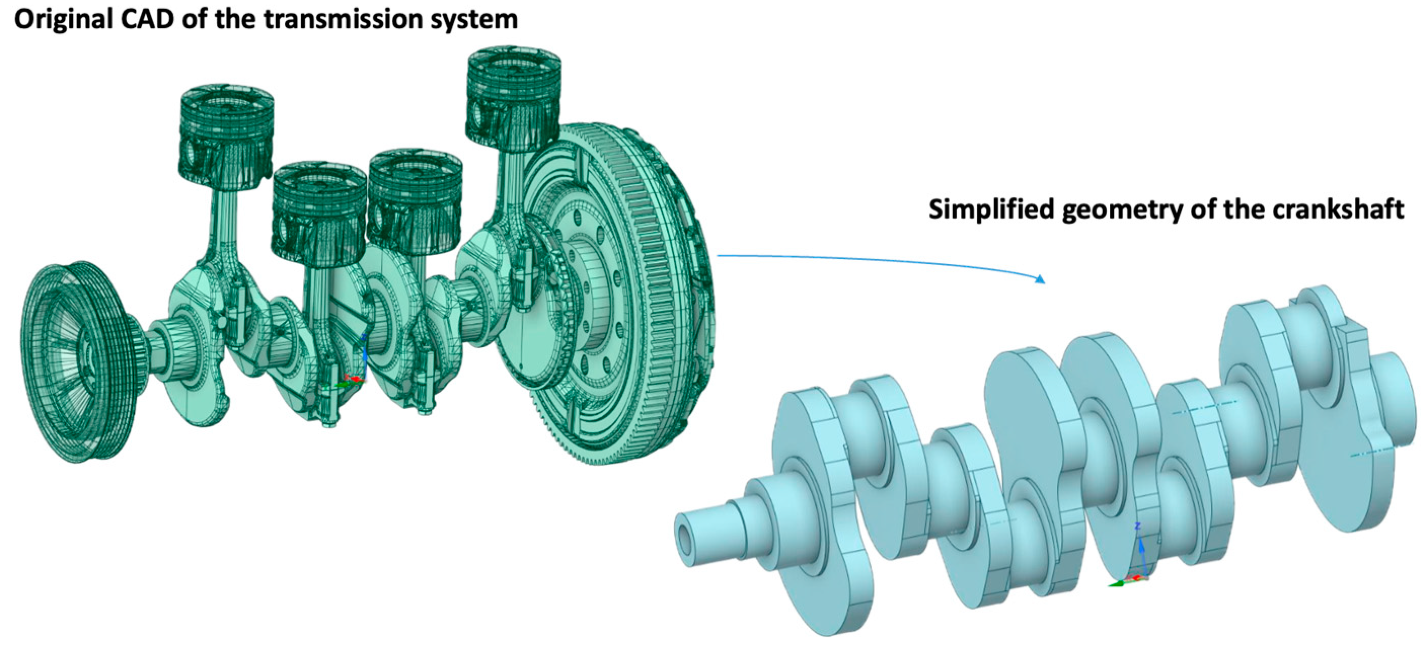
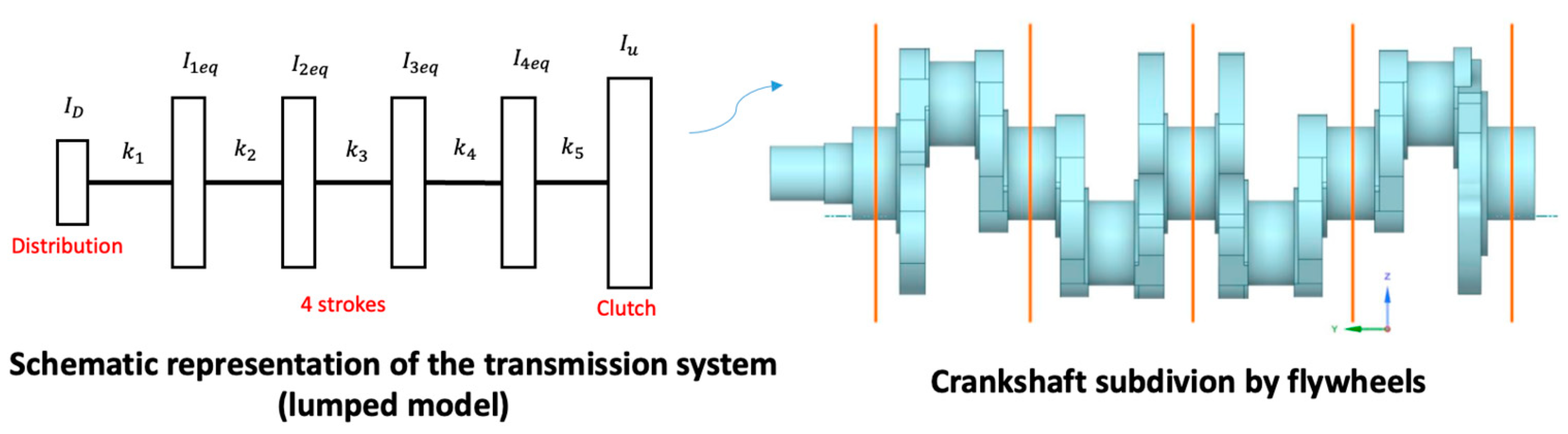
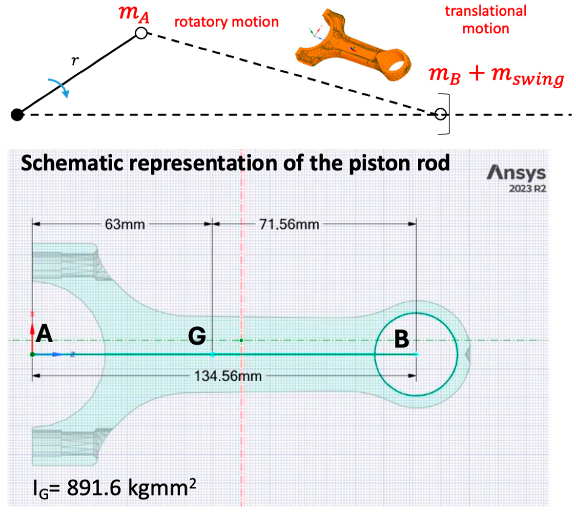
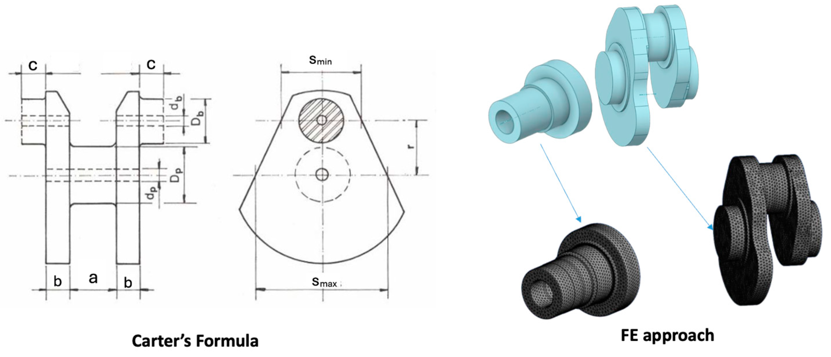
2. Materials and Methods
3. Results and Discussion
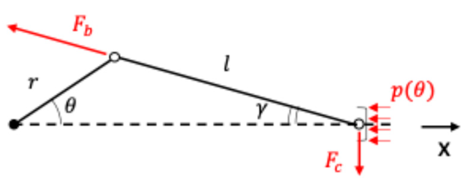
3.1. Lumped System
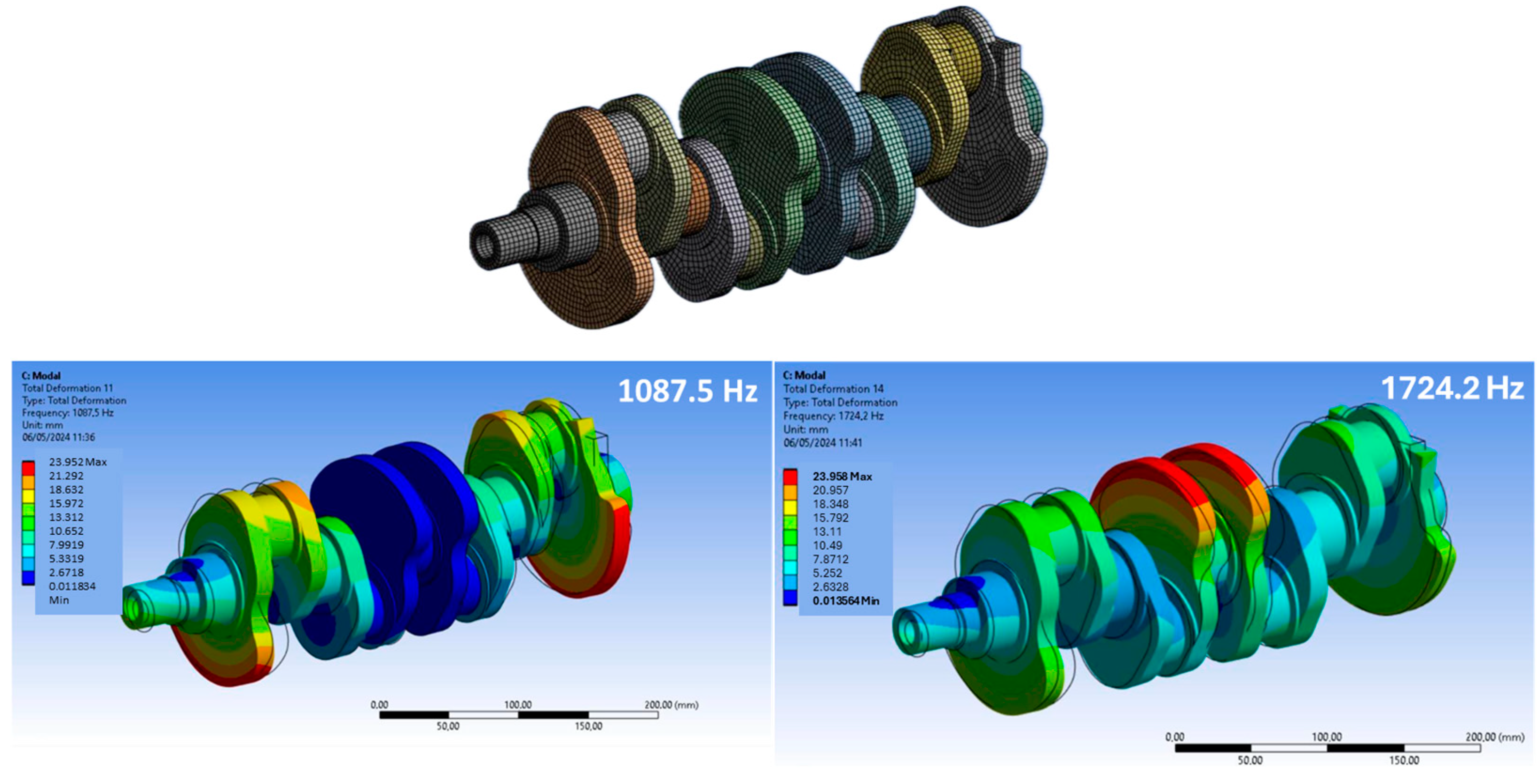
3.2. Modal Analysis
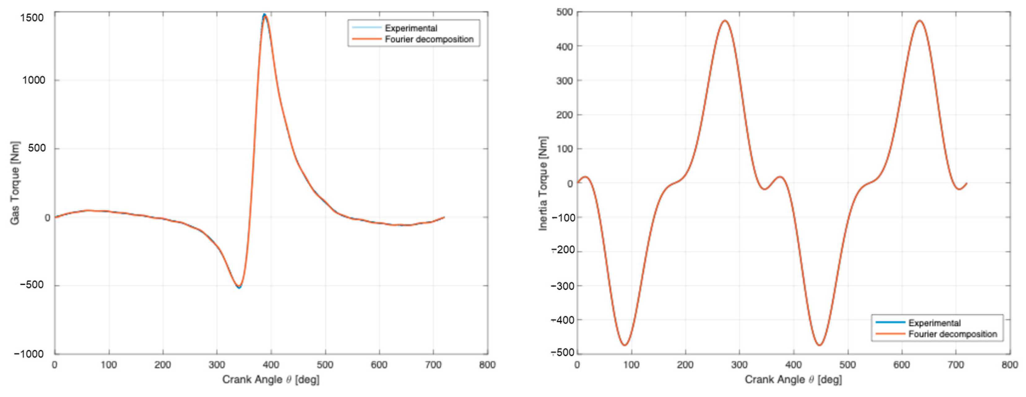
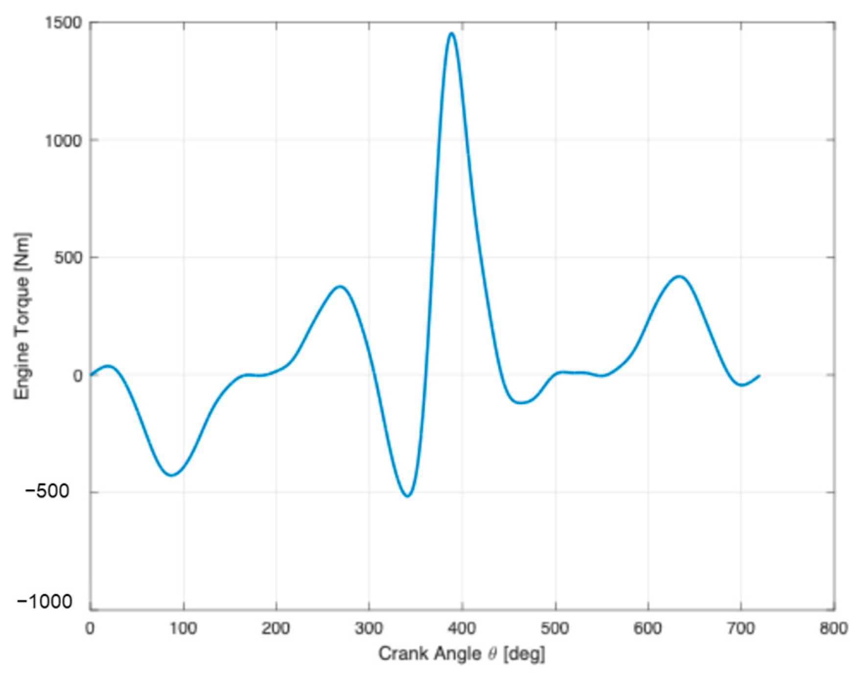
3.3. Frequency Analysis of the Engine Torque
4. Conclusions
Author Contributions
Funding
Institutional Review Board Statement
Informed Consent Statement
Data Availability Statement
Conflicts of Interest
References
- Wang, M.; Xiao, N.; Fan, M. The Torsional Vibration Simulation of the Diesel Engine Crankshaft System Based on Multi-Body Dynamic Model. J. Multi-Body Dyn. 2021, 235, 443–451. [Google Scholar] [CrossRef]
- Brusa, E.; Delprete, C.; Genta, G. Torsional vibration of crankshafts: Effects of non-constant moments of inertia. J. Sound. Vib. 1997, 205, 135–150. [Google Scholar] [CrossRef]
- Charles, P.; Sinha, J.K.; Gu, F.; Lidstone, L.; Ball, A.D. Detecting the Crankshaft Torsional Vibration of Diesel Engines for Combustion Related Diagnosis. J. Sound. Vib. 2009, 321, 1171–1185. [Google Scholar] [CrossRef]
- Burla, R.K.; Seshu, P.; Hirani, H.; Sajanpawar, P.R.; Suresh, H.S. Three Dimensional Finite Element Analysis of Crankshaft Torsional Vibrations Using Parametric Modeling Techniques. SAE Trans. 2003, 112, 2330–2337. [Google Scholar] [CrossRef]
- Cevik, M.C.; Rebbert, M.; Maassen, F. A New Approach for Prediction of Crankshaft Stiffness and Stress Concentration Factors; SAE Technical Papers; SAE: Warrendale, PA, USA, 2010. [Google Scholar] [CrossRef]
- Schagerberg, S.; Mckelvey, T. Instantaneous Crankshaft Torque Measurements-Modeling and Validation; SAE: Warrendale, PA, USA, 2003. [Google Scholar]
- Londhe, A.; Yadav, V.H. Design and Optimization of Crankshaft Torsional Vibration Damper for a 4-Cylinder 4-Stroke Engine; SAE: Warrendale, PA, USA, 2008. [Google Scholar]
- Bremer, R.C.; Schwitzer, W.; Murray, C. A Practical Treatise on Engine Crankshaft Torsional Vibration Control; SAE: Warrendale, PA, USA, 1979. [Google Scholar]
- Sun, L.; Luo, F.; Shang, T.; Chen, H.; Moro, A. Research on Torsional Vibration Reduction of Crankshaft in Off-Road Diesel Engine by Simulation and Experiment. J. Vibroeng. 2018, 20, 345–357. [Google Scholar] [CrossRef]
- Khaliullin, F.; Vagizov, T.; Shakirov, R.; Deryushev, I. Torsional Vibrations of Car Crankshaft Engine Taking into Account Elements of Transmission. In Engineering for Rural Development; Latvia University of Life Sciences and Technologies: Jelgava, Latvia, 2021; Volume 20, pp. 979–985. [Google Scholar]
- Carter, B.C. An Empirical Formula for Crankshaft Stiffness in Torsion. Engineering 1928, 126, 36. [Google Scholar]


| Equivalent INERTIA | [kg mm2] |
|---|---|
| I1 eq | 2.3527 × 10⁴ |
| I2 eq | 5.9814 × 10³ |
| I3 eq | 5.9814 × 10³ |
| I4 eq | 5.9814 × 10³ |
| I5 eq | 6.2972 × 10³ |
| I6 eq | 3.6101 × 10⁵ |
| Equivalent Stiffness [Nmm/rad] | Carter | FE |
|---|---|---|
| k1 eq | 1.4763 × 10⁸ | 1.4763 × 10⁸ |
| k2 eq | 4.8959 × 10⁸ | 4.725 × 10⁸ |
| Critical Frequency | [Hz] |
|---|---|
| ω1 | 399.7 |
| ω2 | 526.7 |
| ω3 | 1130.5 |
| ω4 | 1759.1 |
| Critical Frequency | FE [Hz] | Analytical [Hz] | Error [%] |
|---|---|---|---|
| ω1 | 391.7 | 399.7 | 2.0 |
| ω2 | 568.4 | 526.7 | −7.9 |
| ω3 | 1087.5 | 1130.5 | 3.8 |
| ω4 | 1742.2 | 1759.1 | 1.0 |
Disclaimer/Publisher’s Note: The statements, opinions and data contained in all publications are solely those of the individual author(s) and contributor(s) and not of MDPI and/or the editor(s). MDPI and/or the editor(s) disclaim responsibility for any injury to people or property resulting from any ideas, methods, instructions or products referred to in the content. |
© 2025 by the authors. Licensee MDPI, Basel, Switzerland. This article is an open access article distributed under the terms and conditions of the Creative Commons Attribution (CC BY) license (https://creativecommons.org/licenses/by/4.0/).
Share and Cite
Santonocito, D.; Brusca, S. Analytical and Numerical Methods for the Identification of Torsional Oscillations and Forcing in Internal Combustion Engines. Eng. Proc. 2025, 85, 3. https://doi.org/10.3390/engproc2025085003
Santonocito D, Brusca S. Analytical and Numerical Methods for the Identification of Torsional Oscillations and Forcing in Internal Combustion Engines. Engineering Proceedings. 2025; 85(1):3. https://doi.org/10.3390/engproc2025085003
Chicago/Turabian StyleSantonocito, Dario, and Sebastian Brusca. 2025. "Analytical and Numerical Methods for the Identification of Torsional Oscillations and Forcing in Internal Combustion Engines" Engineering Proceedings 85, no. 1: 3. https://doi.org/10.3390/engproc2025085003
APA StyleSantonocito, D., & Brusca, S. (2025). Analytical and Numerical Methods for the Identification of Torsional Oscillations and Forcing in Internal Combustion Engines. Engineering Proceedings, 85(1), 3. https://doi.org/10.3390/engproc2025085003