Abstract
This paper aims to demonstrate the applicability of a modal selection criterion based on strain energy potential for describing static deformations in a commonly used engineering geometry, specifically a circular plate. The analytical model relies on the definition of internal strain potential energy, enabling the calculation of the energy contribution of each mode derived from a modal analysis to the actual static deformation of the structure. The modal selection is designed to reconstruct the displacement and strain fields under linear elastic conditions, assuming small displacements and strains. This represents the initial phase of a research effort concerning structural health monitoring, where evaluating the displacement, strain, and stress fields is critical for assessing the integrity of mechanical systems. The study examines two loading conditions: axisymmetric and non-axisymmetric bending, which are prevalent in mechanical applications involving circular plates. Modal selection is performed using results from all nodes in the finite element model, as well as from a subset of nodes, demonstrating the feasibility of applying the selection method while reducing the number of equations in the problem. The results indicate a robust comparison between the finite element solution and the modal reconstruction, showcasing the flexibility of the proposed method for the given geometry.
1. Introduction
This paper presents an analytical model aimed at understanding the modal reconstruction of displacement and strain fields in structural mechanics. Modal reconstruction algorithms theoretically enable the reconstruction of the displacement field of an object across its entire domain, based on a limited number of displacement measurements taken at discrete points. It is assumed that the response of a structure to dynamic loading can be accurately described by a certain number of vibration modes only [1]. This approach serves as a powerful analytical tool, enabling the representation of deformation as a linear combination of modal shapes, thus facilitating an efficient analysis of the dynamic behaviour of structures under various loading conditions. The study specifically explores the formulation of displacement and strain vectors expressed through modal coordinates.
The methodology involves establishing a relationship between the measured displacement and strain vectors and their corresponding modal shapes, allowing for the calculation of modal coordinates. These coordinates take into account the contribution of each vibration mode to the deformation, thus forming the backbone of the reconstruction process. A critical aspect of this approach is the selection of significant modes, which is essential not only for accurately representing the structural response but also for optimising computational efficiency.
A significant limitation of modal reconstructions is the selection of modes [2]. For computational efficiency and resource management, it is generally necessary to consider the smallest number of modes possible. Therefore, it is essential to adopt a modal selection criterion that retains the significant modes for reconstructing the deformation of the object under consideration. Among various existing criteria, the one proposed by Borget et al. [3] is noteworthy, as it is based on the strain energy of the finite element solution. The authors develope an additional criterion based on the elastic internal potential energy. The latter criterion is the focus of the present study.
In particular, this work introduces a mode selection criterion based on internal strain potential energy, providing a systematic framework for determining the most influential modes in reconstructing static deformation. By utilising the internal strain potential energy associated with a deformed structure, the reconstruction capability of individual modes can be quantified, enabling the retention of modes that meet predefined energy contribution thresholds.
The efficacy of the proposed modal selection algorithm is demonstrated through a case study involving a finite element model of a circular plate subjected to both axisymmetric and non-axisymmetric loading conditions. The objective is to evaluate the performance of the modal reconstruction process, assessing its accuracy in capturing displacement and strain fields while accounting for variations in loading scenarios. By comparing the results of modal superposition with those obtained from finite element analysis, the study elucidates the strengths and limitations of the proposed methodology.
Ultimately, this research underscores the importance of modal decomposition and selection in structural analysis and contributes valuable insights into potential enhancements for practical applications in the field of engineering mechanics. Future investigations may further refine the selection criteria and explore innovative approaches to improve reconstruction accuracy in complex structural systems.
In the field of structural health monitoring, modal reconstruction can be applied, for instance, to evaluate displacement and stress fields. In fact, consider the case where measurements are available at only a few discrete points on a machine, specifically those points that are functional—i.e., do not compromise the functionality of the machine—and at the same time are accessible for sensor installation. By calculating the weights of the linear combination of modes based on these measurement points, and knowing the modal shapes at all points of the structure through a finite element model, it is possible to estimate the fields of displacement, strain, and, consequently, stress. Imagine the advantages if this procedure were applied for real-time measurements. The main issue remains modal selection, which must be further developed to handle time-varying signals effectively. One could envision future developments of the procedure through machine learning algorithms.
2. Analytical Model
The modal decomposition of the displacement and strain fields involves expressing the deformation of a structure as a linear combination of its modal shapes [2,3,4,5,6,7,8,9]. Let and represent the displacement and strain vectors, respectively. These can be expressed as:
where and are the matrices that, respectively, collect the modal displacements and strains. is called modal coordinate vector. It is a column vector with a number of components equal to the number of modes considered in the decomposition and represents the contribution of each vibration mode to the deformation of the structure.
Once a certain number of measurement points have been selected on the geometry of the component of interest, the vectors and represent the measured displacements and strains, thus forming the input signal. Given the input signal and knowing the modal shapes at the same measurement points, it is possible to calculate the modal coordinates as:
It should be noted that in order to calculate the modal coordinates according to Equations (3) and (4), the number of measurement points times the number of degree of freedom must be greater than or equal to the number of modes considered [9].
To calculate the displacement and strain fields through modal reconstruction, the modes considered must be those most significant in describing the deformation of the structure. Additionally, to reduce computational time, it is necessary not only to retain the most significant modes, but also to keep their number as small as possible, while ensuring the reconstruction error between displacement and strain remains within acceptable limits. For this reason, adopting a mode selection criterion is essential.
Aiming to reconstruct the static deformation of an object through modal superposition, a mode selection criterion based on internal strain potential energy is formulated by the authors. Given a deformed structure, the internal strain potential energy can be expressed as:
where and are, respectively, the strain vector and the elastic matrix, which depends on the elastic properties of material, namely, the shear modulus and Poisson ratio [10,11].
Considering all expanded modes, it is possible to write the internal strain potential energy of the reconstructed solution, obtained by modal superposition. From Equations (5) and (2), the reconstructed internal strain potential energy is:
For each i-th mode the reconstruction contribute in terms of internal strain potential energy is:
The reconstruction capability is defined as the ratio between the energy contribution of a single mode to the static deformation of the object and the total internal strain potential energy of the actual static state. This provides a percentage measure of how much the mode contributes to reconstructing the given deformation:
where the subscript refers to the internal strain potential energy associated to the real deformation. By setting a minimum percentage threshold on the reconstruction capability, all modes that satisfy the following relation are retained:
where is the minimum threshold of the reconstruction capability.
3. Case Study
The mode selection algorithm, described in Section 2, is applied to a finite element (FE) model of a circular plate with axisymmetric geometry and linear elastic, isotropic, homogeneous material. The choice of geometry is motivated by the aim of testing the mode selection algorithm and, consequently, the modal reconstruction using the retained modes for both axisymmetric geometric conditions and axisymmetric as well as non-axisymmetric loading conditions. The objective is to assess how the application of different loads, deviating from the axisymmetric case, influences mode selection and the modal reconstruction error. The comparison is made between the results of a finite element static solution, obtained through the direct inversion of the characteristic equations of the FE problem, and those obtained by modal superposition, using the input signal provided by the strain vector derived from the aforementioned FE solution.
The plate, supported at the outer radius, is annular with an inner radius of 100 mm, an outer radius of 250 mm, and a thickness of 15 mm (Figure 1). Structural steel with a Young’s modulus of , Poisson’s ratio , and density is chosen as the material.
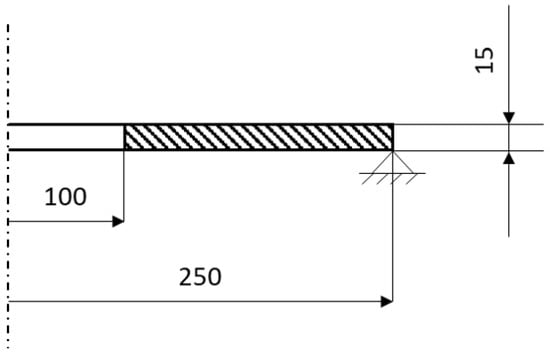
Figure 1.
Schematic representation of the geometry and boundary conditions of the circular plate.
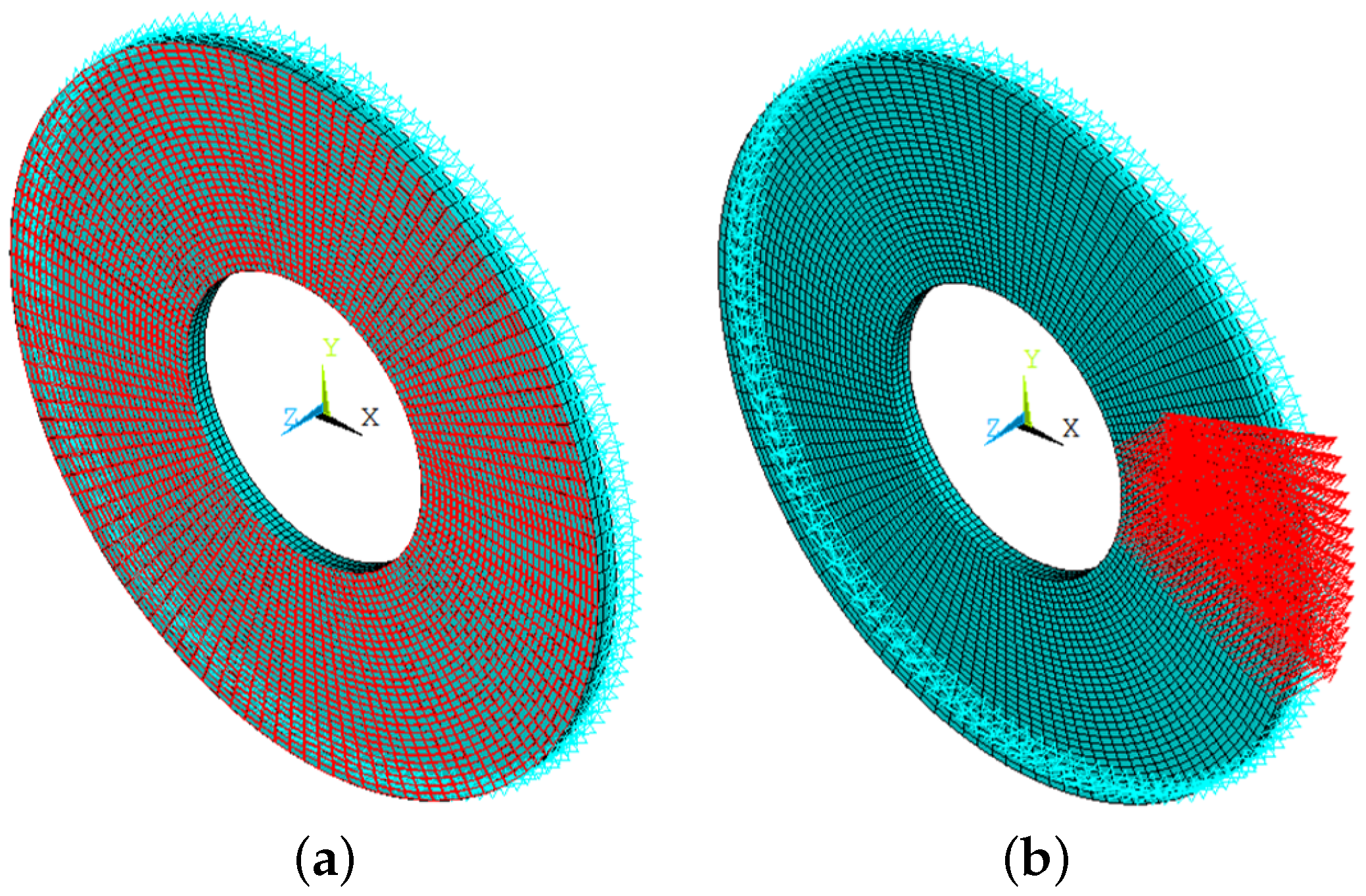
The FE model is implemented using PyMAPDL from PyAnsys. Two element types are considered: SOLID185 and SURF154. The SOLID185 element is used for 3D modelling of solid structures, specifically the circular plate. This element has three degrees of freedom associated with translations in the three spatial directions. The SURF154 element is used to apply surface loads on the upper face of the plate. It is employed for applying axisymmetrically distributed pressure, overlaying the existing solid mesh (Figure 2) [12].
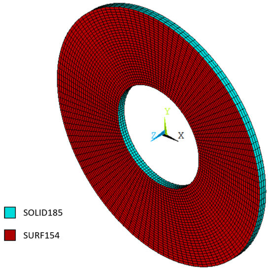
Figure 2.
FE model.
The following two loading conditions are considered:
- Axisymmetric load: uniform pressure in the negative z-direction on the upper surface of the plate, with a magnitude of 0.25 MPa (Figure 3a).
 Figure 3. Load conditions. (a) Axisymmetric load condition. (b) Non-axisymmetric load condition.
 - Non-axisymmetric load: a force with a resultant of 100 kN in the negative z-direction, distributed across the nodes of the upper surface from the angular position of −22.5° to +22.5° (Figure 3b).
The model, including geometry, mesh, and constraints, is first implemented using PyMAPDL (0.68.4, ANSYS Inc., USA, 2024). This model is used both to perform a modal analysis to evaluate the vibration modes of the circular plate and to carry out subsequent static analyses with the two loading configurations, axisymmetric and non-axisymmetric. The subsequent phase of mode selection and superposition is then executed using a Python script (3.11.9, Python Software Foundation, April 2024), which calculates the displacement, strain, and stress fields according to the relationships outlined in Section 2.
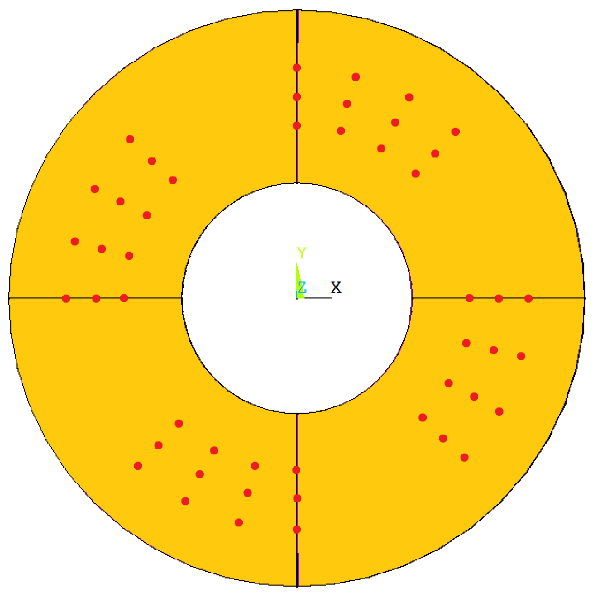
The mode selection is compared for both the axisymmetric and non-axisymmetric cases, considering all the mesh nodes as measurement points for the modal selection. Finally, for the non-axisymmetric case—which the authors consider more interesting in terms of mode selection, as its static deformation requires the superposition of multiple modal shapes to be thoroughly described—the selection algorithm is tested by considering all the mesh nodes and by using only a subset of nodes taken from three different radial coordinates on the upper face of the plate, as illustrated in Figure 4.
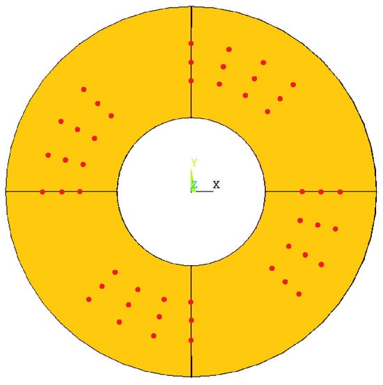
Figure 4.
Measurement nodes (red points) for the non-axisymmetric case.
4. Results
The results of the modal reconstructions are compared with the FE results obtained using Ansys. Two sets of data are presented: total displacement vector and Von Mises equivalent stress. This comparison enables an assessment of the accuracy of the reconstruction for both the displacement and strain fields. Since, in a linear elastic field with small displacements and deformations, stresses are derived by multiplying the material elastic matrix by the strain values [10,11], a comparison of the stress field is also included. The comparison between the FE solution and the reconstructed solution is carried out by calculating the percentage error between the FE and reconstructed values at each node. It should be noted that the mode selection was conducted by setting a minimum of 0.1%.
4.1. Axisymmetric Load Condition
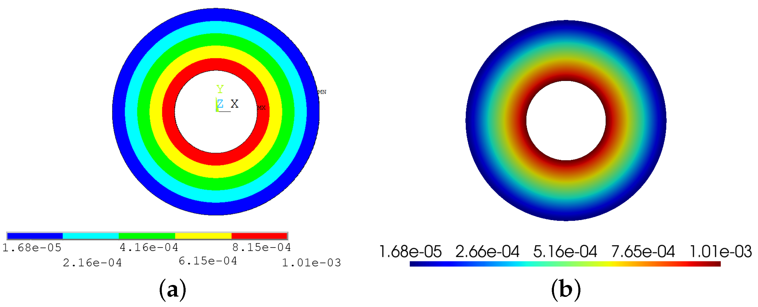
For the circular plate subjected to axisymmetric loading with a constant pressure on the upper surface, both the displacement (Figure 5) and stress (Figure 6) fields exhibit axisymmetry, depending solely on the radial coordinate and not on the circumferential one. This aligns with the overall conditions of axisymmetry in the case under study, which assumes axisymmetry in the geometry, material properties, and applied load.
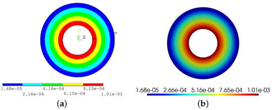
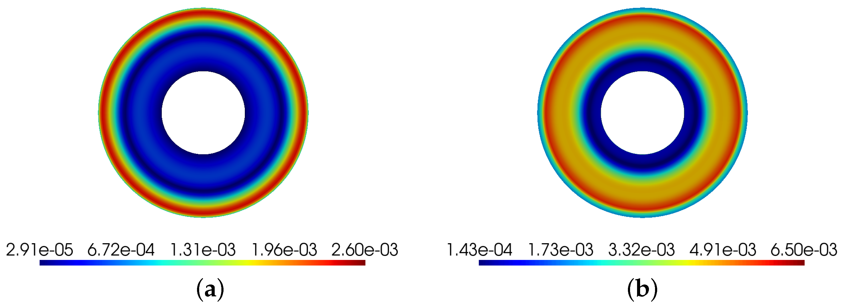
Figure 5.
Displacement vector sum for axisymmetric load condition. The results are presented in metres. (a) FE solution. (b) Reconstructed solution.

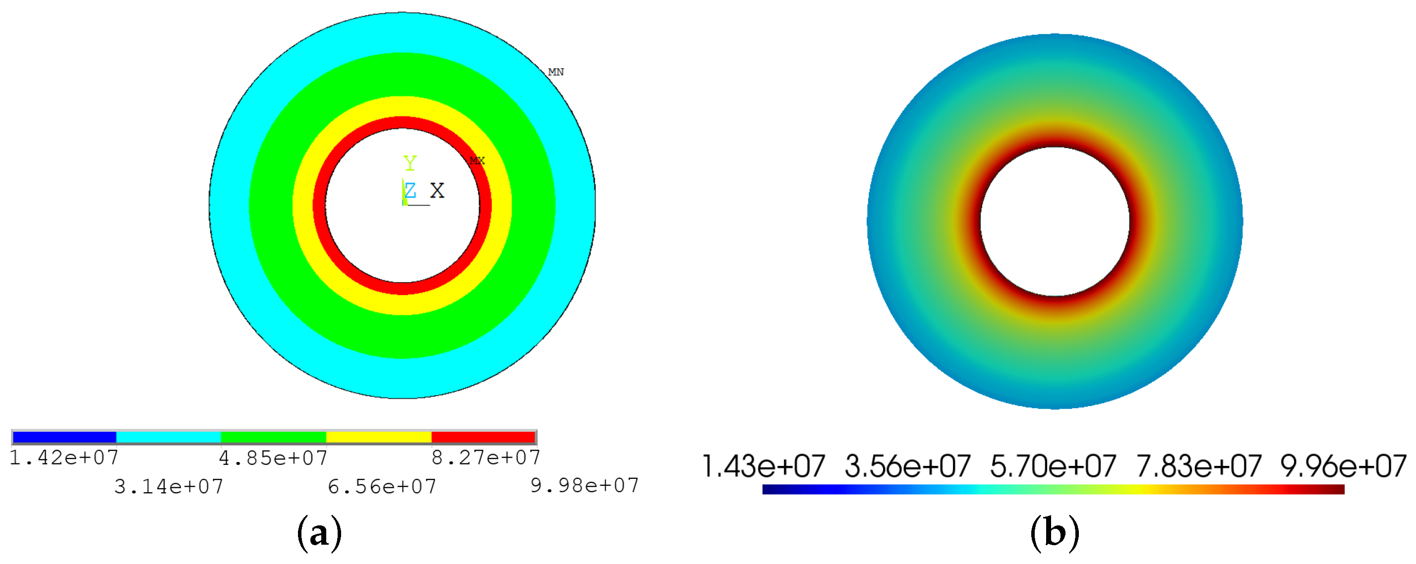
Figure 6.
Von Mises equivalent stress for axisymmetric load condition. The results are presented in pascals. (a) FE solution. (b) Reconstructed solution.
Under the given axisymmetric bending load, only two modes energetically contribute to the deformation reconstruction: modes 1 and 12. The errors are minimal for both the reconstruction of the displacement and stress fields, and consequently for the strain field as well. The maximum error is 0.26% for the displacement and 0.65% for the stress (Figure 7).
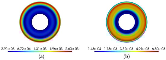
Figure 7.
Relative errors for axisymmetric load condition. (a) Relative errors on displacement vector sum. (b) Relative errors on Von Mises equivalent stress.
4.2. Non-Axisymmetric Load Condition
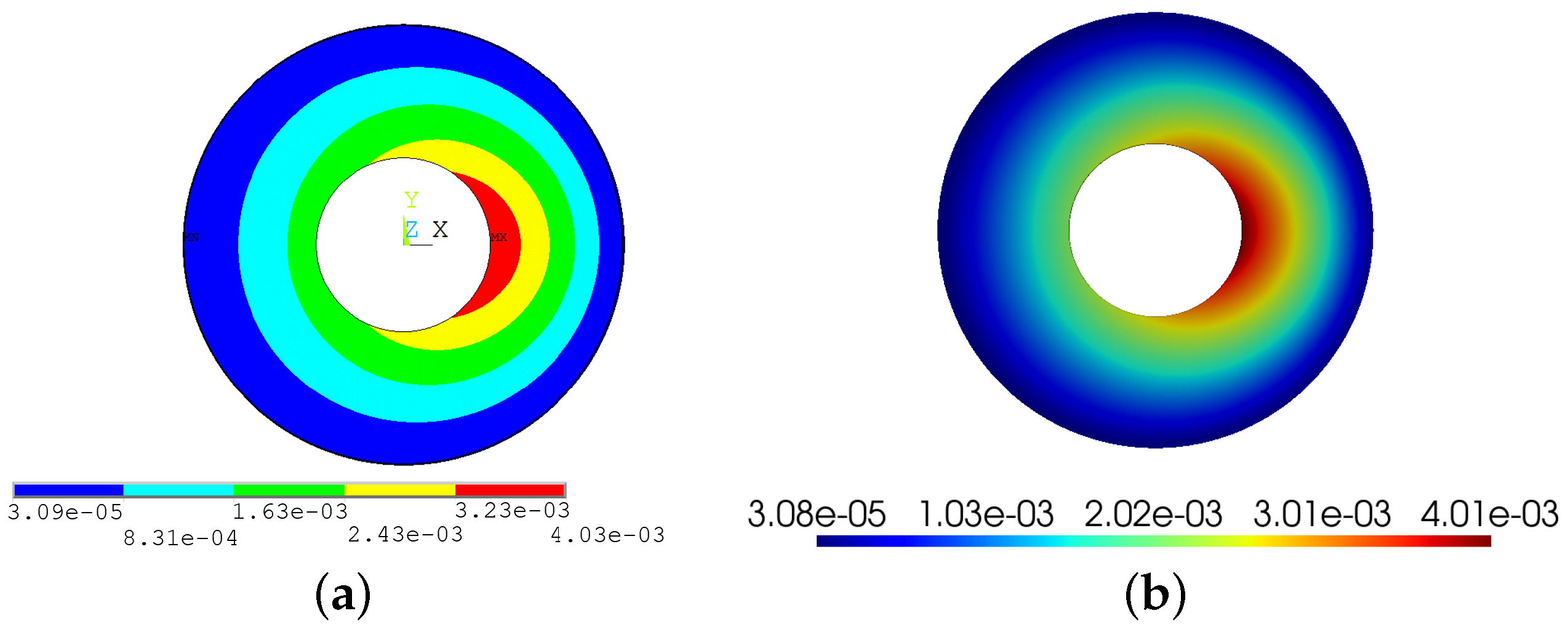
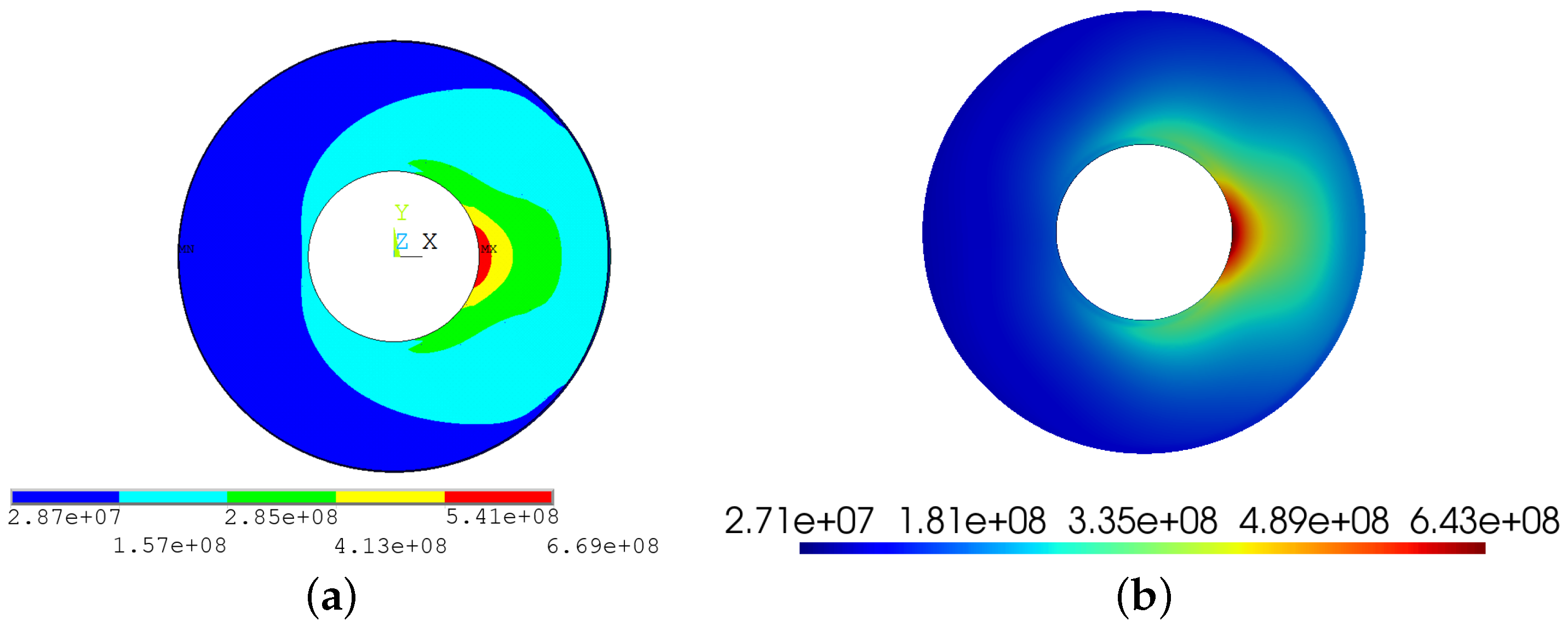
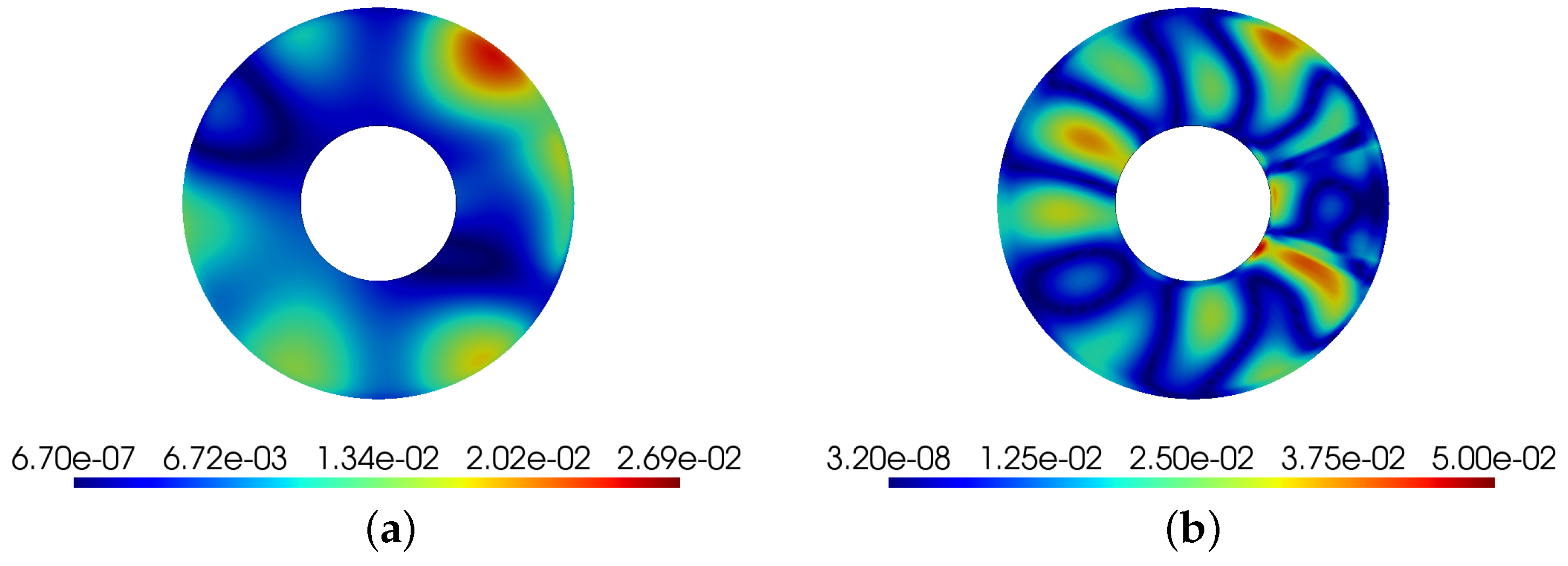
In Section 3, the method of applying the load is discussed, specifically a non-axisymmetric bending load with a resultant of 100 kN applied from the angular coordinate of −22.5° to +22.5°. The results of the finite element (FE) analysis and the reconstruction are presented (Figure 8 and Figure 9). In this case, due to the previously described loading condition, the deformation is non-axisymmetric, which necessitates retaining a greater number of modes that energetically describe the deformation. The retained modes are 1, 2, 3, 4, 7, 15, and 20. The errors recorded are 2.69% for the displacement and 5.00% for the stresses (Figure 10).
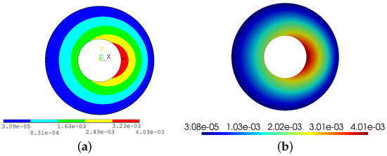
Figure 8.
Displacement vector sum for non-axisymmetric load condition. The results are presented in metres. (a) FE solution. (b) Reconstructed solution.
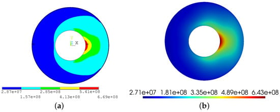
Figure 9.
Von Mises equivalent stress for non-axisymmetric load condition. The results are presented in pascals. (a) FE solution. (b) Reconstructed solution.
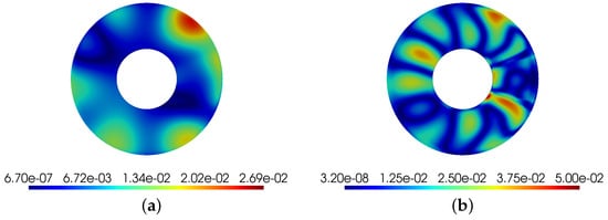
Figure 10.
Relative errors for non-axisymmetric load condition. (a) Relative errors on displacement vector sum. (b) Relative errors on Von Mises equivalent stress.
4.3. Non-Axisymmetric Load Condition and Discrete Number of Measuring Points
For the case of non-axisymmetric loading, which considers a discrete number of measurement nodes for reconstruction rather than the entire mesh, the contours of the relative errors in displacement and strain are presented (Figure 4). In this case, as mentioned in Section 2, the modal selection does not occur through a comparison with the energy contribution of deformation across the entire geometry, but instead considers only the portion of strain energy associated with the nodes selected for the criterion.
Although this approach accounts for a lower amount of energy compared to the scenario considering the entire mesh—since the internal potential deformation energy is calculated by summing the potential energy of each considered node—it is noted that the criterion remains valid, as the same number of modes are retained. However, a higher error is associated with this method compared to the case involving the entire mesh, with errors of 3.09% for displacement and 6.00% for stress (Figure 11). This is attributed to the fact that the reconstruction is performed by modal decomposition, considering the strains of only the selected nodes (Figure 4), and therefore, there is an error in calculating the modal coordinate vector, the component values of which depend on the number of measurement points considered and their arrangement within the geometry.
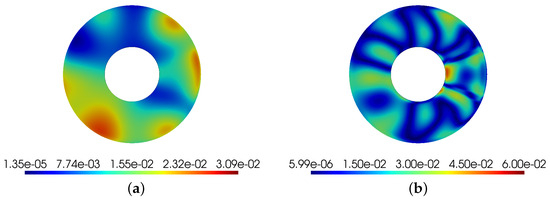
Figure 11.
Relative errors on Von Mises equivalent stress. (a) Relative errors on displacement vector sum. (b) Relative errors for non-axisymmetric load condition.
5. Conclusions
This study has successfully demonstrated the application of a modal selection algorithm for the reconstruction of static deformations in a circular plate subjected to both axisymmetric and non-axisymmetric loading conditions. The modal decomposition technique was employed to express the displacement and strain fields as linear combinations of their respective modal shapes, facilitating an effective analysis of the behaviour of the system under various loading scenarios.
The findings reveal that under axisymmetric loading, a minimal number of modes (specifically modes 1 and 12) were sufficient to achieve accurate reconstruction results, with maximum errors of only 0.26% for displacements and 0.65% for stresses. These low error rates underscore the efficiency of the modal selection criterion based on internal strain potential energy, confirming its validity in the context of modal reconstruction.
Conversely, the non-axisymmetric loading condition necessitated the retention of a greater number of modes to adequately capture the complex deformation characteristics. The reconstruction accuracy remained satisfactory, with recorded errors of 2.69% for displacements and 5.00% for stresses. This demonstrates the robustness of the proposed modal selection algorithm in accommodating increased complexity in loading scenarios.
Additionally, the analysis of a discrete number of measurement nodes highlighted the importance of strategic node selection in modal reconstruction. While this approach resulted in higher errors—3.09% for displacement and 6.00% for stress—it reaffirmed the effectiveness of the modal selection criterion, even when applied to a subset of nodes.
Overall, this research not only validates the modal decomposition and selection methodology but also provides valuable insights into the limitations and potential improvements for practical applications in structural analysis. Future work may explore enhancements in node selection strategies to further reduce reconstruction errors and improve the efficiency of the modal analysis process in complex loading environments.
Author Contributions
Conceptualization, G.L.; methodology, G.L. and P.F.; software, G.L.; validation, G.L. and P.F.; formal analysis, G.L. and P.F.; investigation, G.L. and P.F.; resources, G.L. and P.F.; data curation, G.L. and P.F.; writing—original draft preparation, G.L. and P.F.; writing—review and editing, G.L.; visualization, G.L.; supervision, G.L. and P.F.; project administration, P.F.; funding acquisition, P.F. and M.P. All authors have read and agreed to the published version of the manuscript.
Funding
This research received no external funding.
Institutional Review Board Statement
Not applicable.
Informed Consent Statement
Not applicable.
Data Availability Statement
The data presented in this study are available on request from the corresponding author.
Conflicts of Interest
Author Miriam Parisi was employed by the company Eni S.p.a. The remaining authors declare that the research was conducted in the absence of any commercial or financial relationships that could be construed as a potential conflict of interest. Eni S.p.A. had no role in the design of the study; in the collection, analyses, or interpretation of data; in the writing of the manuscript, or in the decision to publish the results.
References
- Pisoni, A.C.; Santolini, C.; Hauf, D.E.; Dubowsky, S. Displacements in a vibrating body by strain gage measurements. In Proceedings of the Proceedings-SPIE the International Society for Optical Engineering, Orlando, FL, USA, 18–19 April 1995; Citeseer: University Park, PA, USA, 1995; p. 119. [Google Scholar]
- Fanelli, P.; Biscarini, C.; Jannelli, E.; Ubertini, F.; Ubertini, S. Structural health monitoring of cylindrical bodies under impulsive hydrodynamic loading by distributed FBG strain measurements. Meas. Sci. Technol. 2017, 28, 024006. [Google Scholar] [CrossRef]
- Bogert, P.; Haugse, E.; Gehrki, R. Structural shape identification from experimental strains using a modal transformation technique. In Proceedings of the 44th AIAA/ASME/ASCE/AHS/ASC Structures, Structural Dynamics, and Materials Conference, Norfolk, VI, USA, 7–10 April 2003; p. 1626. [Google Scholar]
- Fanelli, P.; Facci, A.L.; Jannelli, E. Live crack damage detection with local strain measurement on solid bodies subjected to hydrodynamic loading. Procedia Struct. Integr. 2018, 8, 539–551. [Google Scholar] [CrossRef]
- Fanelli, P.; Mercuri, A.; Trupiano, S.; Vivio, F.; Falcucci, G.; Jannelli, E. Live reconstruction of global loads on a powerboat using local strain FBG measurements. Procedia Struct. Integr. 2019, 24, 949–960. [Google Scholar] [CrossRef]
- Fanelli, P.; Trupiano, S.; Belardi, V.G.; Vivio, F.; Jannelli, E. Structural health monitoring algorithm application to a powerboat model impacting on water surface. Procedia Struct. Integr. 2019, 24, 926–938. [Google Scholar] [CrossRef]
- Esposito, M.; Gherlone, M. Composite wing box deformed-shape reconstruction based on measured strains: Optimization and comparison of existing approaches. Aerosp. Sci. Technol. 2020, 99, 105758. [Google Scholar] [CrossRef]
- Kang, L.H.; Kim, D.K.; Han, J.H. Estimation of dynamic structural displacements using fiber Bragg grating strain sensors. J. Sound Vib. 2007, 305, 534–542. [Google Scholar] [CrossRef]
- Li, L.; Zhong, B.S.; Geng, Z.Y.; Sun, W. Structural Shape Reconstruction of FBG Flexible Plate Using Modal Superposition Method. In Proceedings of the International Design Engineering Technical Conferences and Computers and Information in Engineering Conference, Cleveland, OH, USA, 6–9 August 2017; American Society of Mechanical Engineers: New York, NY, USA, 2017; Volume 58226, p. V008T12A038. [Google Scholar] [CrossRef]
- Casini, P.; Vasta, M. Scienza Delle Costruzioni, 4th ed.; CittàStudi: Segrate, Italy, 2019. [Google Scholar]
- Timoshenko, S.; Goodier, J. Theory of Elasticity, 2nd ed.; McGraw-Hill Book Company: New York, NY, USA, 1951. [Google Scholar]
- Elements Reference ANSYS, Release 2020 R2; Ansys Inc.: Southpointe, PA, USA, 2020.


Disclaimer/Publisher’s Note: The statements, opinions and data contained in all publications are solely those of the individual author(s) and contributor(s) and not of MDPI and/or the editor(s). MDPI and/or the editor(s) disclaim responsibility for any injury to people or property resulting from any ideas, methods, instructions or products referred to in the content. |
© 2025 by the authors. Licensee MDPI, Basel, Switzerland. This article is an open access article distributed under the terms and conditions of the Creative Commons Attribution (CC BY) license (https://creativecommons.org/licenses/by/4.0/).