Proceeding Paper

Mechanical Multiscale Lithium-Ion Battery Modeling for Optimized Battery Pack Design †

Department of Mechanical and Aerospace Engineering, Politecnico di Torino, Corso duca degli Abruzzi, 24, 10129 Turin, Piemonte, Italy
*
Author to whom correspondence should be addressed.
Presented at the 53rd Conference of the Italian Scientific Society of Mechanical Engineering Design (AIAS 2024), Naples, Italy, 4–7 September 2024.
Eng. Proc. 2025, 85(1), 48; https://doi.org/10.3390/engproc2025085048
Published: 27 March 2025

Abstract

:
In the automotive and working vehicle industry, lithium-ion batteries are a strategic component affecting the design, cost, and performance of vehicles. The electrochemical processes which allow the battery to deliver or store electrical energy involve the interaction of lithium ions with the electrode microstructure, causing the mechanical deformation of the electrode. The deformation of the electrode microstructure has two effects: mechanical degradation and the resulting overall performance decay of the battery, and macroscopic battery deformation. In this work, macroscopic battery deformation originating at the atomic scale is investigated with a multi-physics homogenized model in two steps: first, the composite electrode is modeled with a representative volume element; secondly, the battery is modeled by homogenizing the contribution of the hundreds of composite electrode layers. Then, the impact of the deformation of the single battery on the whole battery module is numerically investigated. The deformation of the single battery computed with the model is validated with experimental measurements quantifying the macroscopic battery deformation during operation. Then, different design solutions for the battery module are investigated to optimize its energetic and volumetric efficiency while maintaining safe levels of battery module deformation.

1. Introduction

The ecological transition we are experiencing in recent years is causing the fast growth of electric-powered vehicles, with the aim of reducing the environmental impact throughout the entire cycle life of the product. The transition is not only restricted to passenger vehicles but extends also to working vehicles, which can significantly reduce their environmental impact [1,2] as well as representing a technological advancement in the field [3]. Lithium-ion batteries (LIBs) are currently the most commonly used energy storage systems for electric or hybrid vehicles, even if their field of application is much broader.
LIBs consist of numerous stacked electrode foils, encased in a hard or soft shell, depending on the format of the battery. The electrode is a composite material created by mixing micrometric active material particles with conductive agents and binders, forming a slurry that is spread over the current collector, dried, and pressed to achieve the required porosity before being filled with the electrolyte.
During battery operation, lithium ions are inserted into and extracted from the active material of the electrodes, enabling the flow of current through the external circuit. These intercalation reactions cause the volume deformation of the microstructure of the active material, with its crystalline structure changing in volume in response to the amount of lithium intercalated. As a result, the micrometric particles expand or contract, leading to the swelling or shrinkage of the entire electrode layer and consequently the whole battery [4,5]. The outer metallic case provides stiffness, reducing the extent of the macroscopic volume change.
Typically, LIBs swell during charging due to the larger expansion of the negative electrode compared to the contraction of the positive. Conversely, the battery shrinks during discharge. This volume change has significant implications in the design of battery packs, as the arrangement of the batteries in the module should allow for these deformations, as well as the irreversible deformation that occurs with aging, to avoid excessive stress in the pack.
The intercalation process and the correlated volume change also cause stress in the electrode microstructure [6,7,8,9], leading to crack propagation [10,11,12,13,14,15,16], and electrode degradation [17,18,19,20,21].
In recent years, increased attention has been paid to the mechanical behavior of LIBs during operation, with several methods developed to measure volume change: laser sensors [22,23], dial indicators [24,25], load cells [26,27], optic fibers (both embedded and external) [28,29,30], strain gauges [31,32], digital image correlation [33], piezoelectric sensors [34], internal pressure sensors [35,36], and eddy current devices [37]. Some studies have analyzed thickness change curves, showing their dependence on current rates and hysteresis between charge and discharge cycles [38,39,40].
From a modeling perspective, a few multi-physics models have been proposed to study LIB volume changes at the battery scale under various conditions [23,24,25,41], some of which are based on the homogenization approach [42,43]. Nevertheless, there are currently no studies analyzing the structural behavior of the battery pack when subjected to charging and discharging that take into account deformation originating at the atomic scale due to intercalation phenomena and the arrangement of the batteries in the pack.
This work presents a multiscale model based on the homogenized approach implemented in COMSOL Multiphysics to calculate the stress and deformation in the module with different battery arrangements. The deformation of each single battery is computed from the intercalation-induced volume change of the active material at the atomic scale. The reference volume element of the composite electrode is identified to model it as a homogeneous material and compute the overall electrode deformation. The same homogenization approach is adopted again at the cell level (electrode, current collector, and separator) to compute battery deformation originating from the deformation of electrodes.
The model is applied to a battery module consisting of 18 lithium iron phosphate (LFP) batteries arranged on two rows. The gap between the batteries is considered as the design parameter, with a low gap increasing the energy and power density of the module, but at the same time causing higher stress because of the constrained expansion of the batteries. An acceptable trade-off is identified with the proposed model. The numerical results obtained from the model at battery level are validated through experimental measurements using optical displacement sensors, measuring single-battery deformation during charging and discharging.

2. Materials and Methods

In this section, the multi-physics model framework is explained, focusing particularly on the mechanical model, which is summarized in Figure 1. Briefly, the physics-based Doyle–Fuller–Newman (DFN) electrochemical model is used to compute the concentration of lithium ions within the electrode according to the current delivered by the battery for a certain amount of time, given as a boundary condition. This model also gives the resulting voltage of the battery, which is used to validate the electrochemical model with the experimental measurements.
The concentration of lithium ions in the active material particle at the micro-scale is the input of the mechanical model, as outlined in Figure 1, which allows for computing the macroscopic battery deformation. Due to the numerical difficulties given by the inhomogeneity of the components of the lithium ion battery, a two-step homogenization approach is followed, as described in the following sections.

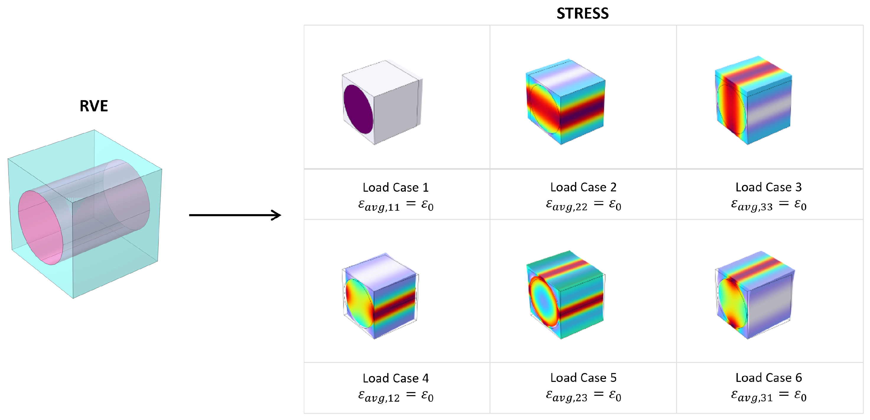
2.1. Numerical Homogenization

Systems often exhibit behavior that spans multiple spatial scales, meaning that small-scale phenomena can significantly influence large-scale behavior and vice versa. Homogenization is the technique used to obtain the macroscopic properties of a material or a system from the microscopic behavior of its constituents. The advantage is the possibility of treating a complex structure as homogeneous without neglecting its heterogeneity in the lower scales.
Several analytical homogenization models have been proposed to investigate composite materials’ behavior: the simplest is the volume average method, followed by the Voigt–Reuss model [44,45] and its upgrades, the Halpin–Tsi–Nielsen and Hashin–Rosen models [46]. With the increasing complexity at the micro-scale, analytical methods can be very intricate or can lead to inaccurate results. In this case, homogenized properties should be performed numerically. One of the most common numerical homogenization methods is finite element homogenization, which consists of extracting a representative volume element (RVE) or a repeating unit cell (RUC) from the macroscopic system and applying finite element analysis—with proper load cases and boundary conditions—to obtain the desired homogenized properties. The difference between RVE and RUC stands in the boundary conditions because the latter is characterized by periodicity and the former is just a representative volume [47].
In structural mechanics, the objective is the computation of the homogenized stiffness matrix from the heterogeneous RVE or RUC. This is made possible by imposing an arbitrary strain to the representative domain and evaluating the corresponding induced stress, as shown in Figure 2. In the most general case—a 3D anisotropic homogenization—six load cases are needed: three normal strains and three decoupled shear strains (Equation (1)).
ε a v g , 11 0 0 0 0 0 0 ε a v g , 22 0 0 0 0 0 0 ε a v g , 33 0 0 0 0 0 0 ε a v g , 12 0 0 0 0 0 0 ε a v g , 23 0 0 0 0 0 0 ε a v g , 31
For each load case, the six corresponding stress are averaged inside the domain to obtain a single homogenized value for each component (Equation (2)). Finally, each element of the homogenized stiffness matrix can be computed as the ratio between the averaged stress and the imposed strain as shown in Equation (3).
σ a v g , 11 ( ε a v g , i j ) σ a v g , 22 ( ε a v g , i j ) σ a v g , 33 ( ε a v g , i j ) σ a v g , 12 ( ε a v g , i j ) σ a v g , 23 ( ε a v g , i j ) σ a v g , 31 ( ε a v g , i j ) i , j { 1 , 2 , 3 }
D i j = σ i ( ε j ) ε j i , j { 1 , , 6 }

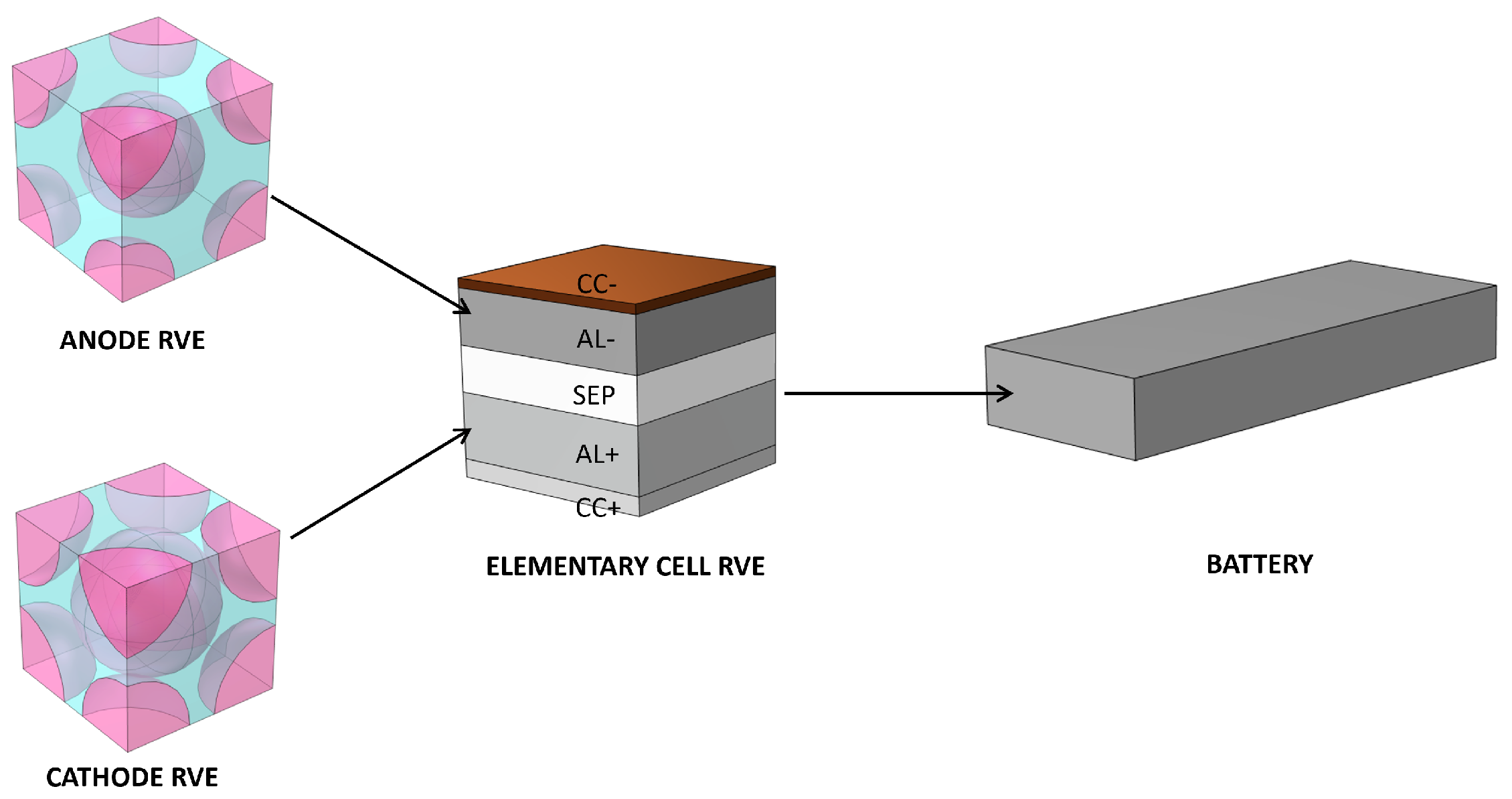
2.2. Battery Homogenization

In many fields, accurately simulating the behavior of batteries is crucial, not just for their electrical performance but also for understanding how they respond to different mechanical, thermal, and environmental conditions. The battery’s complex internal architecture, composed of numerous layers and nano-structured materials, presents a unique challenge in numerical simulation as it becomes impractical and computationally expensive to model every detail directly. This challenge can be overcome by treating the active layers and the whole battery as homogenized material. The purpose of this work is to develop a multiscale model to analyze the mechanical response of a battery module without explicitly modeling its microstructure.
The composite electrodes are mainly composed by the electrolyte and active materials particles, which can be assumed to be spherical, as proven by microscope images [23], and other additives. Due to the particles’ arrangement, a body-centred cubic (BCC) cell has been chosen as the RVE of the electrode layer to perform the numerical homogenization. For an isotropic RVE, just a single normal strain load case is sufficient to extract the material parameters thanks to the relationship between the elastic properties. The homogenized electrode is one of the components of the RVE of the composite elementary cell, which is a layered stack composed by the two current collectors, the separator, and the electrodes themselves. In this case, the resulting homogenized material is transversely isotropic due to its RVE layered structure. Finally, the entire battery is characterized by the homogenized single-cell element and its homogenized stiffness matrix. In this way, it can be easily managed in structural analysis. A back-calculation can be performed moving from larger to smaller scales to compute the stress distribution at the micro-scale.
A scheme of this two-step homogenization is presented in Figure 3. The parameters used to perform the homogenization are reported in Table 1.

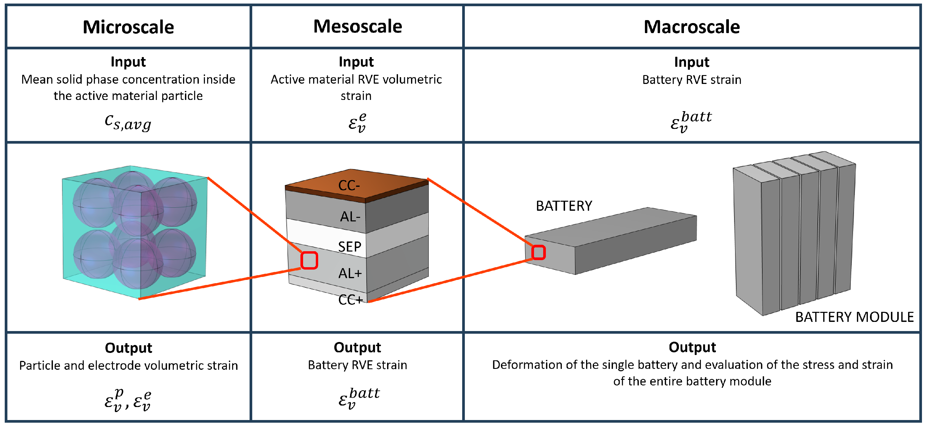
2.3. Multiscale Model

A comprehensive multiscale model has been developed using COMSOL Multiphysics to investigate the mechanical behavior of a battery module during charging and discharging. The lithium-ion intercalation and deintercalation induce active material particle swelling and shrinkage at the micro-scale. This chemical volumetric strain is proportional to the concentration of the intercalated species inside the particle through the partial molar volume Ω as shown in Equation (4) [51].
d ε v p = Ω d c s
The partial molar volume of graphite is influenced by the phase transitions that occur during the lithium-ion intercalation. In fact, the graphite partial molar volume is dependent on the anode state of lithiation x in L i x C 6 and on the current intensity. On the other side, LFP shows a constant partial molar volume [52]. Partial molar volume and the respective lithiation-induced deformation of the crystal structure of graphite and LFP are reported in Figure 4a and Figure 4b, respectively.
Current intensity is indicated in the normalized form as “C” or “C-rate”, where 1C corresponds to the current (Ampere) needed to completely discharge the battery from a fully charged state in 1 h.
The lithium-ion concentration in the solid phase c s is computed with the DFN model implemented in COMSOL Multiphysics, which completely resolves the electrochemistry of the battery, computing the voltage of the electrode and the concentration of lithium ions within, giving the current as a boundary condition [53,54,55]. The transport of lithium ions within the active material particles of the electrode is governed by Fick’s law, as reported in Equation (5), where the lithium flux J at the particle boundary is given by the kinetic Equation (Butler–Volmer), depending on the overpotential (difference between the actual potential and the equilibrium potential). A greater current leads to higher potential unbalance and thus a higher lithium ions flux, with the ions being extracted from the particles of the electrode of one polarity and inserted into the particles of the electrode with the opposite polarity.
J = D ( c s r Ω c s R T σ h r )
The concentration of lithium ions in the electrode particles (r-coordinate) is computed as a function of time, and considering a certain number of particles in electrode thickness (z-coordinate) ( c s = c s ( z , r , t ) ). Then, different concentration profiles result in the different particles located in the electrode going from the current collector to the separator. Then, the particle average concentration is extracted from different electrode points in order to obtain more accurate deformations, since the average concentration in the particle is not constant along the electrode thickness.
The particle deformation—expressed in Equation (4)—induces the whole electrode strain. In the model, the representative volume element of the electrode—modeled with the proper porosity—has been used to evaluate the mechanical strain of the electrode layers ε v e . This can be achieved by inducing particle swelling/shrinkage due to lithium concentration as a hygroscopic phenomenon in COMSOL, and evaluating the RVE volume deformation. Subsequently, the RVE of the unit cell has been designed to account for the deformations of the few previously computed electrodes and to obtain the volumetric strain of the whole battery. Due to the small thickness of the electrode layers with respect to their in-plane dimensions, a plane-strain condition can be assumed [24,56]:
ε i n p l a i n e = 0 ; ε o u t o f p l a n e e = ε v e
Finally, the strain computed at the single-battery level is used to validate the model by comparing the numerical thickness change during charge and discharge with the experimental measurements at different C-rates. Secondly, once the correctness of the deformation of the single battery has been confirmed, the whole module can be numerically simulated to investigate its mechanical behavior in different geometrical and operational scenarios. The mechanical properties of the single battery case and of the whole module case are reported in Table 2 while the input of the electrochemical model can be found in the authors’ work [12].

3. Experiment

Three commercial LFP/graphite prismatic LIB samples are subjected to electrical, thermal, and mechanical characterization to assess their performance. The tests involve measuring voltage, temperature, and deformation responses to various charge and discharge currents. Charge rates range from C/20 to C/2, while discharge rates span from C/20 to 3C, respecting manufacturer specifications. Each charge/discharge test is performed in the state of a charge range of (SOC) 0%–100% and is repeated five times on the same battery sample, with three different samples tested for each chemistry. Battery deformation is monitored during operation using a dedicated testing setup, measuring the thickness variation of the battery with laser sensors, as detailed in a previous study by the author [38]. All tests are conducted in a thermostatic chamber at a constant ambient temperature of 20 °C.

4. Results

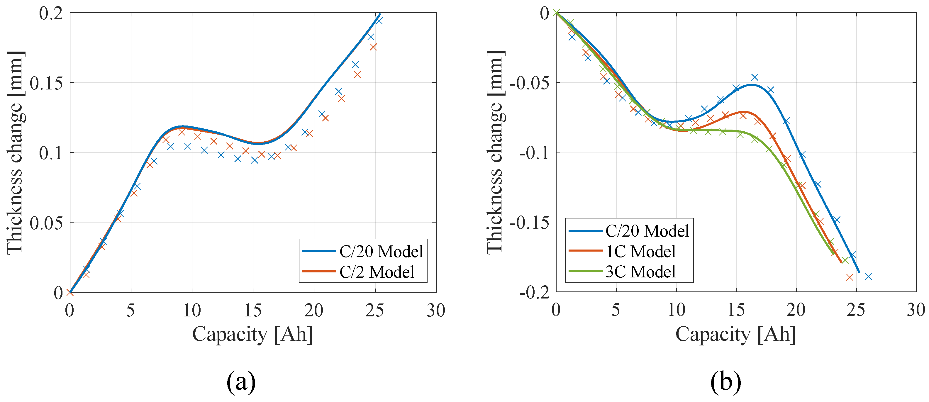
4.1. Single Battery Level

Complete charge and discharge cycles (SOC 0–100%) are simulated and compared with experimental measurements to assess the validity of the model.
At first, the voltage response of the LIB samples to different current rates is compared to the measurements in Figure 5.
The comparison between the model and the experiments shows a good agreement, confirming the correctness of the electrochemical model, which gives the concentration of the electrode particles that are the origin of the macroscopic mechanical deformation.
The comparison between the thickness change of the single battery occurring during charge and discharge at different current rates computed with the model and the experimental measurements is reported in Figure 6. The comparison is satisfactory as the model can correctly replicate the macroscopic deformation of the battery measured experimentally, starting from the concentration of lithium ions in the electrode microstructure. The dependence on the current rate observed during discharge is modeled by defining a concentration-dependent partial molar volume, as detailed in an author’s previous work [23]. The reason for this behavior is the lithiation mechanisms of graphite: different lithium-graphite phases (or stages), according to their lithium content, form when lithium ions intercalate in the crystal structure of graphite. Stage II and Stage IIL have a lower volume than other stages (with respect to lithium content), causing the clear reduction in thickness to increase during charge (and vice versa during discharge), as shown in Figure 6. Stage IIL has an even lower volume than stage II and it shows a peculiar behavior as it appears at low discharge rates and gradually fades as the discharge rate increases, affecting the structural deformation of the graphite crystalline structure. On the other hand, stage IIL does not appear at all during charge [57]. This behavior leaves the thickness change curve unaffected by the current rate during charge (Figure 6a), and causes the progressively more prominent peak, decreasing the current rate during discharge (Figure 6b).

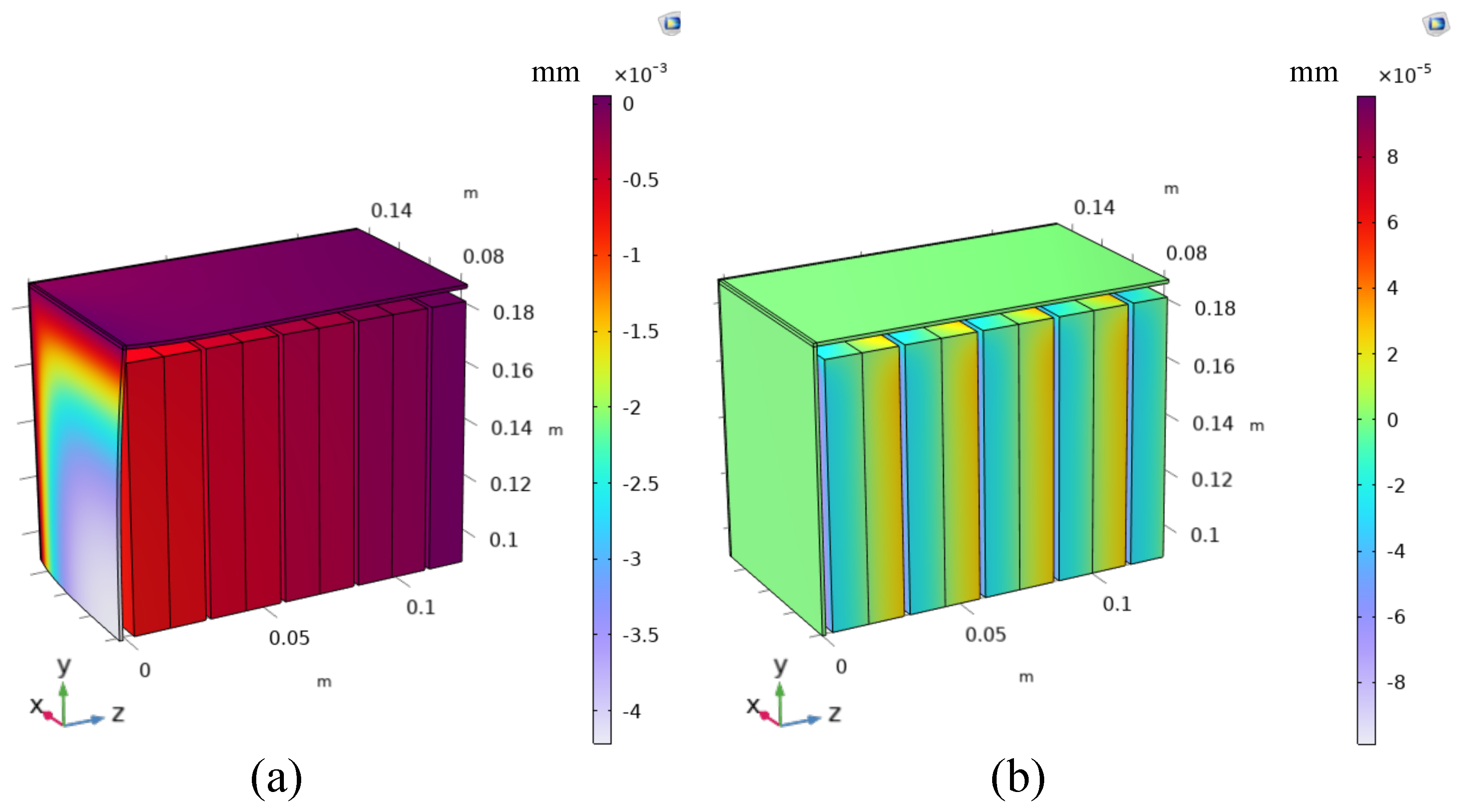
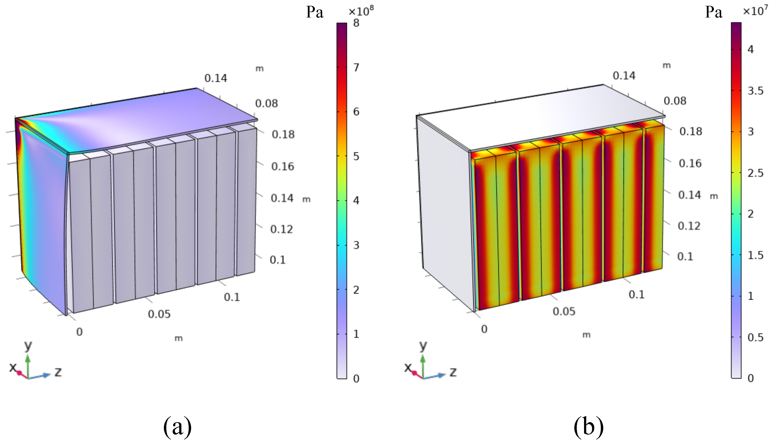
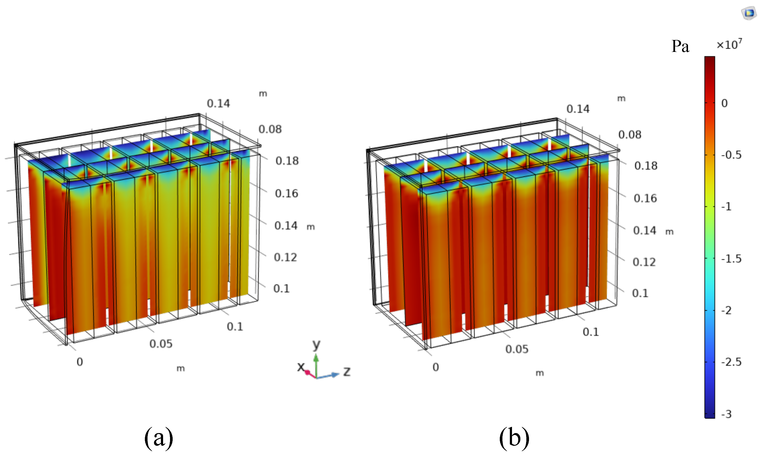
4.2. Battery Module Level

A 60 V battery module consisting of 18 batteries is studied from the structural point of view, analyzing how the deformation of each single battery affects the deformation and the stress in the module. The case of the battery module is made of structural steel plates of 1.2 mm in thickness. Two design solutions for the battery module are studied with different battery arrangements:
  • Batteries are packed with no gaps between each other.
  • A gap equal to 0.5 mm is left between the batteries. This gap could be also smaller, at most equal to the half of the reversible deformation computed or measured for each single battery (0.2 mm in this case). Nevertheless, from a constructive point of view, it would be difficult to leave such a small gap. For this reason, 0.5 mm is chosen as a realistic and conservative scenario.
In the first design solution, the reversible deformation of the batteries during charge and discharge causes severe deformation in the case of the battery module, as reported in Figure 7a, as well as severe stress within each battery cell, as reported in Figure 8a and Figure 9a. In the second design solution, the reversible deformation of the batteries during charge and discharge is entirely accommodated by the gap left between the batteries, mitigating the stress within the cell and eliminating the deformation of the external casing of the battery module.
The price to be paid for this design solution is the increased size of the battery module and the consequent decrease in its energy and power density. In fact, the volume of the module goes from being 6.9 dm 3 in design solution 1 to 7.3 dm 3 in design solution 2, with a modest increase of only 6% in volume, and therefore an equal percentage reduction in energy and power density. From these considerations, it turns out that it is beneficial to consider the reversible deformation of the batteries during operation in the design of the battery module, as a modest increase in the battery module volume allows for mitigating the structural issues caused by battery deformation, resulting in stress in the battery itself and in the casing of the module.
This gap is not only beneficial from the structural point of view but it also gives benefits from the thermal point of view, as it improves the cooling and thermal management of the battery module.
Figure 9 shows the stress in the z direction in three cross-sections on the y-z plane inside the batteries. Design solution 1 (Figure 9a) results in a more severe compressive stress within the batteries because of the constrained expansion with respect to design solution 2 (Figure 9b).
Nevertheless, the top and the bottom of the case of each individual battery provide a high membrane stiffness and constrain the expansion in the z direction of the inner electrodes near these areas, giving rise to high and localized compressive stress. On the other hand, the case provides a flexural stiffness–lower than the membrane–to the large surfaces of the batteries, allowing for deformation of the inner electrodes in the areas away from the edges, and consequently lowering the stress.

5. Conclusions

This study presents a multiscale model based on the homogenization approach to analyze the mechanical behavior of lithium-ion battery modules caused by intercalation-induced deformation at the atomic scale. At first, the model is applied to single LFP batteries, showing the ability to capture the reversible deformation occurring during charge and discharge cycles. The model results closely matches the experimental data (deformation and voltage), ensuring its reliability.
Then, a battery module consisting of 18 LFP cells, arranged in two rows, is studied considering two design solutions: one with no gaps between the batteries, and another with a 0.5 mm gap. The results shows that the design with no gap leads to significant stress in both the batteries and the module casing, while introducing a small gap effectively mitigated these stresses by allowing for battery expansion. This solution results in a modest 6% increase in volume and a similar decrease in energy and power density. These findings highlight the importance of considering mechanical deformation in battery module design to balance energy and power density with mechanical integrity. The model offers a practical solution for improving the structural stability and longevity of LIB modules, as a small decrease in energy and power density bring high benefits from the structural point of view.

Author Contributions

Conceptualization, D.C., F.P., F.M. and A.S.; methodology, D.C., F.P., S.M. and S.S.; software, D.C. and S.S.; validation, D.C. and F.P.; formal analysis, D.C., F.P., F.M. and S.M.; investigation, S.S., D.C. and F.P.; resources, A.S.; data curation, D.C.; writing—original draft preparation, S.S. and D.C.; writing—review and editing, D.C., F.M., S.M., F.P. and A.S.; visualization, D.C.; supervision, F.M. and A.S.; project administration, A.S.; funding acquisition, A.S. All authors have read and agreed to the published version of the manuscript.

Funding

This research received no external funding.

Institutional Review Board Statement

Not applicable.

Informed Consent Statement

Not applicable.

Data Availability Statement

Data are contained within the article.

Conflicts of Interest

The authors declare no conflicts of interest.

References

  1. Martelli, S.; Mocera, F.; Somà, A. Carbon footprint of an orchard tractor through a life-cycle assessment approach. Agriculture 2023, 13, 1210. [Google Scholar] [CrossRef]
  2. Martelli, S.; Martini, V.; Mocera, F.; Soma’, A. Life Cycle Assessment Comparison of Orchard Tractors Powered by Diesel and Hydrogen Fuel Cell. Energies 2024, 17, 4599. [Google Scholar] [CrossRef]
  3. Martelli, S.; Mocera, F.; Soma, A. Autonomous Driving Strategy for a Specialized Four-Wheel Differential-Drive Agricultural Rover. AgriEngineering 2024, 6, 1937–1958. [Google Scholar] [CrossRef]
  4. Clerici, D. Mechanics of Lithium-Ion Batteries—A Modelling and Experimental Perspective. Ph.D. Thesis, Department of Mechanical and Aerospace Engineering, Politecnico di Torino, Turin, Italy, 2024. [Google Scholar]
  5. Clerici, D.; Pistorio, F.; Mocera, F.; Somà, A. Mechanical characterization and modelling of lithium-ion batteries. Transp. Res. Procedia 2023, 70, 276–283. [Google Scholar]
  6. Clerici, D.; Mocera, F.; Somà, A. Analytical solution for coupled diffusion induced stress model for lithium-ion battery. Energies 2020, 13, 1717. [Google Scholar] [CrossRef]
  7. Clerici, D.; Mocera, F.; Somà, A. Shape Influence of Active Material Micro-Structure on Diffusion and Contact Stress in Lithium-Ion Batteries. Energies 2020, 14, 134. [Google Scholar] [CrossRef]
  8. Clerici, D.; Mocera, F. Micro-scale modeling of Lithium-ion battery. IOP Conf. Ser. Mater. Sci. Eng. 2021, 1038, 012007. [Google Scholar] [CrossRef]
  9. Clerici, D. Diffusion-induced stress amplification in phase-transition materials for electrodes of lithium-ion batteries. Int. J. Mech. Sci. 2024, 281, 109541. [Google Scholar]
  10. Pistorio, F.; Clerici, D.; Mocera, F.; Somà, A. Review on the Experimental Characterization of Fracture in Active Material for Lithium-Ion Batteries. Energies 2022, 15, 9168. [Google Scholar] [CrossRef]
  11. Pistorio, F.; Clerici, D.; Mocera, F.; Somà, A. Review on the numerical modeling of fracture in active materials for lithium ion batteries. J. Power Sources 2023, 566, 232875. [Google Scholar]
  12. Pistorio, F.; Clerici, D.; Mocera, F.; Somà, A. Coupled electrochemical–mechanical model for fracture analysis in active materials of lithium ion batteries. J. Power Sources 2023, 580, 233378. [Google Scholar]
  13. Clerici, D.; Pistorio, F.; Somà, A. Design and fracture mechanics of lithium-ion batteries. Procedia Struct. Integr. 2024, 58, 23–29. [Google Scholar] [CrossRef]
  14. Pistorio, F.; Clerici, D.; Somà, A. Analytical computation of stress intensity factor for active material particles of lithium ion batteries. Eng. Fract. Mech. 2023, 292, 109597. [Google Scholar]
  15. Pistorio, F.; Clerici, D. Analytical computation of stress intensity factor for multi-physics problems. In IOP Conference Series: Materials Science and Engineering; IOP Publishing: Bristol, UK, 2024; Volume 1306, p. 012009. [Google Scholar]
  16. Clerici, D.; Mocera, F.; Pistorio, F. Analysis of fracture behaviour in active materials for lithium ion batteries. In IOP Conference Series: Materials Science and Engineering; IOP Publishing: Bristol, UK, 2022; Volume 1214, p. 012018. [Google Scholar]
  17. Clerici, D.; Pistorio, F.; Somà, A. Aging diagnostics in lithium-ion batteries with differential mechanical measurements. Appl. Energy 2025, 386, 125524. [Google Scholar] [CrossRef]
  18. Birkl, C.R.; Roberts, M.R.; McTurk, E.; Bruce, P.G.; Howey, D.A. Degradation diagnostics for lithium ion cells. J. Power Sources 2017, 341, 373–386. [Google Scholar] [CrossRef]
  19. Gantenbein, S.; Schönleber, M.; Weiss, M.; Ivers-Tiffée, E. Capacity fade in lithium-ion batteries and cyclic aging over various state-of-charge ranges. Sustainability 2019, 11, 6697. [Google Scholar] [CrossRef]
  20. Chen, D.; Kramer, D.; Mönig, R. Chemomechanical fatigue of LiMn1.95Al0.05O4 electrodes for lithium-ion batteries. Electrochim. Acta 2018, 259, 939–948. [Google Scholar] [CrossRef]
  21. Mocera, F.; Somà, A.; Clerici, D. Study of aging mechanisms in lithium-ion batteries for working vehicle applications. In Proceedings of the 2020 Fifteenth International Conference on Ecological Vehicles and Renewable Energies (EVER), Monte-Carlo, Monaco, 10–12 September 2020; pp. 1–8. [Google Scholar]
  22. Clerici, D.; Mocera, F. Experimental Characterization of Lithium-Ion Cell Strain Using Laser Sensors. Energies 2021, 14, 6281. [Google Scholar] [CrossRef]
  23. Clerici, D.; Mocera, F.; Soma, A. Electrochemical–mechanical multi-scale model and validation with thickness change measurements in prismatic lithium-ion batteries. J. Power Sources 2022, 542, 231735. [Google Scholar]
  24. Mohtat, P.; Lee, S.; Sulzer, V.; Siegel, J.B.; Stefanopoulou, A.G. Differential Expansion and Voltage Model for Li-ion Batteries at Practical Charging Rates. J. Electrochem. Soc. 2020, 167, 110561. [Google Scholar] [CrossRef]
  25. Rieger, B.; Schlueter, S.; Erhard, S.V.; Schmalz, J.; Reinhart, G.; Jossen, A. Multi-scale investigation of thickness changes in a commercial pouch type lithium-ion battery. J. Energy Storage 2016, 6, 213–221. [Google Scholar] [CrossRef]
  26. Mohan, S.; Kim, Y.; Siegel, J.B.; Samad, N.A.; Stefanopoulou, A.G. A phenomenological model of bulk force in a li-ion battery pack and its application to state of charge estimation. J. Electrochem. Soc. 2014, 161, A2222. [Google Scholar] [CrossRef]
  27. Figueroa-Santos, M.A.; Siegel, J.B.; Stefanopoulou, A.G. Leveraging Cell Expansion Sensing in State of Charge Estimation: Practical Considerations. Energies 2020, 13, 2653. [Google Scholar] [CrossRef]
  28. Raghavan, A.; Kiesel, P.; Sommer, L.W.; Schwartz, J.; Lochbaum, A.; Hegyi, A.; Schuh, A.; Arakaki, K.; Saha, B.; Ganguli, A.; et al. Embedded fiber-optic sensing for accurate internal monitoring of cell state in advanced battery management systems part 1: Cell embedding method and performance. J. Power Sources 2017, 341, 466–473. [Google Scholar] [CrossRef]
  29. Ganguli, A.; Saha, B.; Raghavan, A.; Kiesel, P.; Arakaki, K.; Schuh, A.; Schwartz, J.; Hegyi, A.; Sommer, L.W.; Lochbaum, A.; et al. Embedded fiber-optic sensing for accurate internal monitoring of cell state in advanced battery management systems part 2: Internal cell signals and utility for state estimation. J. Power Sources 2017, 341, 474–482. [Google Scholar] [CrossRef]
  30. Nascimento, M.; Novais, S.; Ding, M.S.; Ferreira, M.S.; Koch, S.; Passerini, S.; Pinto, J.L. Internal strain and temperature discrimination with optical fiber hybrid sensors in Li-ion batteries. J. Power Sources 2019, 410, 1–9. [Google Scholar] [CrossRef]
  31. Willenberg, L.K.; Dechent, P.; Fuchs, G.; Sauer, D.U.; Figgemeier, E. High-precision monitoring of volume change of commercial lithium-ion batteries by using strain gauges. Sustainability 2020, 12, 557. [Google Scholar] [CrossRef]
  32. Hemmerling, J.; Fill, A.; Birke, K.P. Analysis of the age-, current-and temperature-dependent expansion of cylindrical NCM| Graphite Li-ion battery cells using strain gauges. J. Energy Storage 2024, 99, 113177. [Google Scholar]
  33. Jones, E.M.; Silberstein, M.N.; White, S.R.; Sottos, N.R. In Situ Measurements of Strains in Composite Battery Electrodes during Electrochemical Cycling. Exp. Mech. 2014, 54, 971–985. [Google Scholar] [CrossRef]
  34. Gold, L.; Bach, T.; Virsik, W.; Schmitt, A.; Müller, J.; Staab, T.E.; Sextl, G. Probing lithium-ion batteries’ state-of-charge using ultrasonic transmission—Concept and laboratory testing. J. Power Sources 2017, 343, 536–544. [Google Scholar] [CrossRef]
  35. Schmitt, J.; Kraft, B.; Schmidt, J.P.; Meir, B.; Elian, K.; Ensling, D.; Keser, G.; Jossen, A. Measurement of gas pressure inside large-format prismatic lithium-ion cells during operation and cycle aging. J. Power Sources 2020, 478, 228661. [Google Scholar] [CrossRef]
  36. Hahn, S.; Theil, S.; Kroggel, J.; Birke, K.P. Pressure Prediction Modeling and Validation for Lithium-Ion Pouch Cells in Buffered Module Assemblies. J. Energy Storage 2021, 40, 102517. [Google Scholar]
  37. Plotnikov, Y.; Karp, J.; Knobloch, A.; Kapusta, C.; Lin, D. Eddy current sensor for in-situ monitoring of swelling of Li-ion prismatic cells. AIP Conf. Proc. 2015, 1650, 434–442. [Google Scholar] [CrossRef]
  38. Clerici, D.; Martelli, S.; Mocera, F.; Somà, A. Mechanical characterization of lithium-ion batteries with different chemistries and formats. J. Energy Storage 2024, 84, 110899. [Google Scholar]
  39. Grimsmann, F.; Brauchle, F.; Gerbert, T.; Gruhle, A.; Knipper, M.; Parisi, J. Hysteresis and current dependence of the thickness change of lithium-ion cells with graphite anode. J. Energy Storage 2017, 12, 132–137. [Google Scholar] [CrossRef]
  40. Oh, K.Y.; Siegel, J.B.; Secondo, L.; Kim, S.U.; Samad, N.A.; Qin, J.; Anderson, D.; Garikipati, K.; Knobloch, A.; Epureanu, B.I.; et al. Rate dependence of swelling in lithium-ion cells. J. Power Sources 2014, 267, 197–202. [Google Scholar] [CrossRef]
  41. Sauerteig, D.; Hanselmann, N.; Arzberger, A.; Reinshagen, H.; Ivanov, S.; Bund, A. Electrochemical-mechanical coupled modeling and parameterization of swelling and ionic transport in lithium-ion batteries. J. Power Sources 2018, 378, 235–247. [Google Scholar]
  42. Gupta, P.; Gudmundson, P. A multi-scale model for simulation of electrochemically induced stresses on scales of active particles, electrode layers, and battery level in lithium-ion batteries. J. Power Sources 2021, 511, 230465. [Google Scholar]
  43. Gupta, P.; Gudmundson, P. Modeling of local electrode stresses and pressures in lithium-ion battery packs using three-dimensional homogenization. J. Power Sources 2023, 582, 233514. [Google Scholar] [CrossRef]
  44. Voigt, W. Ueber die Beziehung zwischen den beiden Elasticitätsconstanten isotroper Körper. Ann. Der Phys. 1889, 274, 573–587. [Google Scholar] [CrossRef]
  45. Reuß, A. Berechnung der Fließgrenze von Mischkristallen auf Grund der Plastizitätsbedingung für Einkristalle. Zamm-Z. Fur Angew. Math. Und Mech. 1929, 9, 49–58. [Google Scholar]
  46. Halpin, J.C. Effects of Environmental Factors on Composite Materials. Technical Report. 1969. Available online: https://apps.dtic.mil/sti/tr/pdf/ADA306357.pdf (accessed on 20 May 2024).
  47. Drago, A.; Pindera, M.J. Micro-macromechanical analysis of heterogeneous materials: Macroscopically homogeneous vs periodic microstructures. Compos. Sci. Technol. 2007, 67, 1243–1263. [Google Scholar] [CrossRef]
  48. Qi, Y.; Hector, L.G.; James, C.; Kim, K.J. Lithium Concentration Dependent Elastic Properties of Battery Electrode Materials from First Principles Calculations. J. Electrochem. Soc. 2014, 161, F3010. [Google Scholar] [CrossRef]
  49. Christensen, J.; Newman, J. Stress Generation and Fracture in Lithium Insertion Materials. J. Solid State Electrochem. 2006, 10, 293–319. [Google Scholar] [CrossRef]
  50. Sahraei, E.; Bosco, E.; Dixon, B.; Lai, B. Microscale failure mechanisms leading to internal short circuit in Li-ion batteries under complex loading scenarios. J. Power Sources 2016, 319, 56–65. [Google Scholar] [CrossRef]
  51. Prussin, S. Generation and Distribution of Dislocations by Solute Diffusion. J. Appl. Phys. 1961, 32, 1876–1881. [Google Scholar] [CrossRef]
  52. Koerver, R.; Zhang, W.; de Biasi, L.; Schweidler, S.; Kondrakov, A.O.; Kolling, S.; Brezesinski, T.; Hartmann, P.; Zeier, W.G.; Janek, J. Chemo-mechanical expansion of lithium electrode materials–on the route to mechanically optimized all-solid-state batteries. Energy Environ. Sci. 2018, 11, 2142–2158. [Google Scholar]
  53. Doyle, M.; Fuller, T.F.; Newman, J. Modeling of galvanostatic charge and discharge of the lithium/polymer/insertion cell. J. Electrochem. Soc. 1993, 140, 1526. [Google Scholar]
  54. Newman, J.; Tiedemann, W. Porous-electrode theory with battery applications. AIChE J. 1975, 21, 25–41. [Google Scholar] [CrossRef]
  55. Dao, T.S.; Vyasarayani, C.P.; McPhee, J. Simplification and order reduction of lithium-ion battery model based on porous-electrode theory. J. Power Sources 2012, 198, 329–337. [Google Scholar] [CrossRef]
  56. Rieger, B.; Schlueter, S.; Erhard, S.V.; Jossen, A. Strain propagation in lithium-ion batteries from the crystal structure to the electrode level. J. Electrochem. Soc. 2016, 163, A1595. [Google Scholar]
  57. Taminato, S.; Yonemura, M.; Shiotani, S.; Kamiyama, T.; Torii, S.; Nagao, M.; Ishikawa, Y.; Mori, K.; Fukunaga, T.; Onodera, Y.; et al. Real-time observations of lithium battery reactions—operando neutron diffraction analysis during practical operation. Sci. Rep. 2016, 6, 1–12. [Google Scholar]
Figure 1. Model workflow. From the DFN electrochemical model, the averaged concentration inside the particle allows for obtaining the particle and the electrode strain. The electrode strains are then coupled in the battery RVE, which is composed of the two current collectors, the two active layers, and the separator, to obtain the battery strain. Finally, the whole battery or the battery module can be involved in the structural simulation.
Engproc 85 00048 g001
Figure 2. Example of finite element analysis of the the stress induced by the six strain load cases to a unidirectional fiber representative volume element.
Engproc 85 00048 g002
Figure 3. Two-step homogenization: the heterogeneous structure of the composite electrode is homogenized inside the unit cell RVE. Then, the unit cell is homogenized at the battery level.
Engproc 85 00048 g003
Figure 4. Partial molar volume and the respective lithiation−induced deformation of the crystal structure of (a) graphite and (b) LFP as a function of the lithium content expressed with the lithiation index.
Engproc 85 00048 g004
Figure 5. Model (solid lines) and experimental (crosses) comparison of the voltage profile of the single battery during (a) discharge and (b) charge at different current rates in LFP LIBs.
Engproc 85 00048 g005
Figure 6. Model (solid lines) and experimental (crosses) comparison of the thickness change profile of the single battery during (a) discharge and (b) charge at different current rates in LFP LIBs.
Engproc 85 00048 g006
Figure 7. Deformation of the battery module (internal of the batteries plus case of the module) in (a) the design solution 1 and (b) the design solution 2. Thanks to the symmetry, just the top left of the battery module is explicitly simulated.
Engproc 85 00048 g007
Figure 8. Von Mises stress in the battery module (internal of the batteries plus case of the module) in (a) design solution 1 and (b) design solution 2. Thanks to the symmetry, just the top left of the battery module is explicitly simulated.
Engproc 85 00048 g008
Figure 9. Stress in the z direction in the y-z plane cross section of the internal of the batteries in (a) design solution 1 and (b) design solution 2. Thanks to the symmetry, just the top left of the battery module is explicitly simulated.
Engproc 85 00048 g009
Table 1. Homogenization parameters: l, from the literature; m, measured from SEM images; c, calculated.
DomainPropertySymbolValueUnit
Cathode Active LayerParticle Young’s Modulus E p c a t 125 l [48]GPa
Particle Poisson’s ratio ν p c a t 0.3 l [48]-
Particle radius r p c a t 0.03 m μ m
Porosity ϵ p c a t 0.608 c-
Thickness t a l c a t 72 m μ m
Anode Active LayerParticle Young’s Modulus E p a n 15 l [49]GPa
Particle Poisson’s ratio ν p a n 0.3 l [49]-
Particle radius r p a n 10 m μ m
Porosity ϵ p a n 0.434 c-
Thickness t a l a n 60 m μ m
Cathode Current CollectorYoung’s Modulus E c c c a t 70 lGPa
Poisson’s ratio ν c c c a t 0.3 l-
Thickness t c c c a t 12 m μ m
Anode Current CollectorYoung’s Modulus E c c a n 110 lGPa
Poisson’s ratio ν c c a n 0.3 l-
Thickness t c c a n 10 m μ m
SeparatorYoung’s Modulus E s e p 0.4 l [50]GPa
Poisson’s ratio ν s e p 0.01 l [50]-
Thickness t s e p 33 m μ m
Table 2. Mechanical parameters.
DomainPropertySymbolValueUnit
Battery CaseYoung’s Modulus E c a s e b a t 70GPa
Poisson’s ratio ν c a s e b a t 0.33-
Thickness t c a s e b a t 0.8mm
Width w c a s e b a t 70mm
Height h c a s e b a t 27mm
Length l c a s e b a t 185mm
Module CaseYoung’s Modulus E c a s e m o d 210GPa
Poisson’s ratio ν c a s e m o d 0.3-
Thickness t c a s e m o d 1.2mm
Disclaimer/Publisher’s Note: The statements, opinions and data contained in all publications are solely those of the individual author(s) and contributor(s) and not of MDPI and/or the editor(s). MDPI and/or the editor(s) disclaim responsibility for any injury to people or property resulting from any ideas, methods, instructions or products referred to in the content.

