
Real-Time Kinematic Positioning Using Multi-Frequency Smartphone Measurements †


Abstract
:1. Introduction
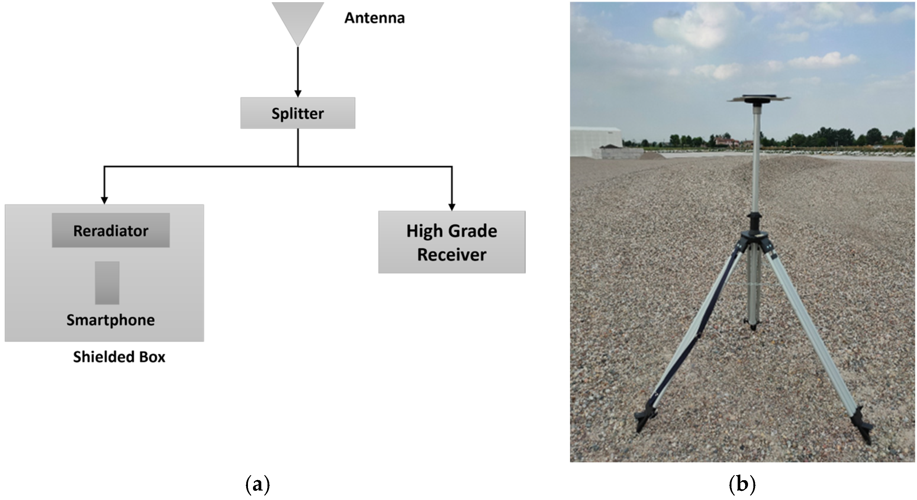
2. Methodology and Experimental Set-Up
- TTFF: number of epochs needed to achieve the first fix position solution in RTK mode.
- Percentage of fixed solutions.
- Horizontal/vertical accuracy (computed with respect to the position surveyed exploiting the NET-G5 receiver used as a reference).
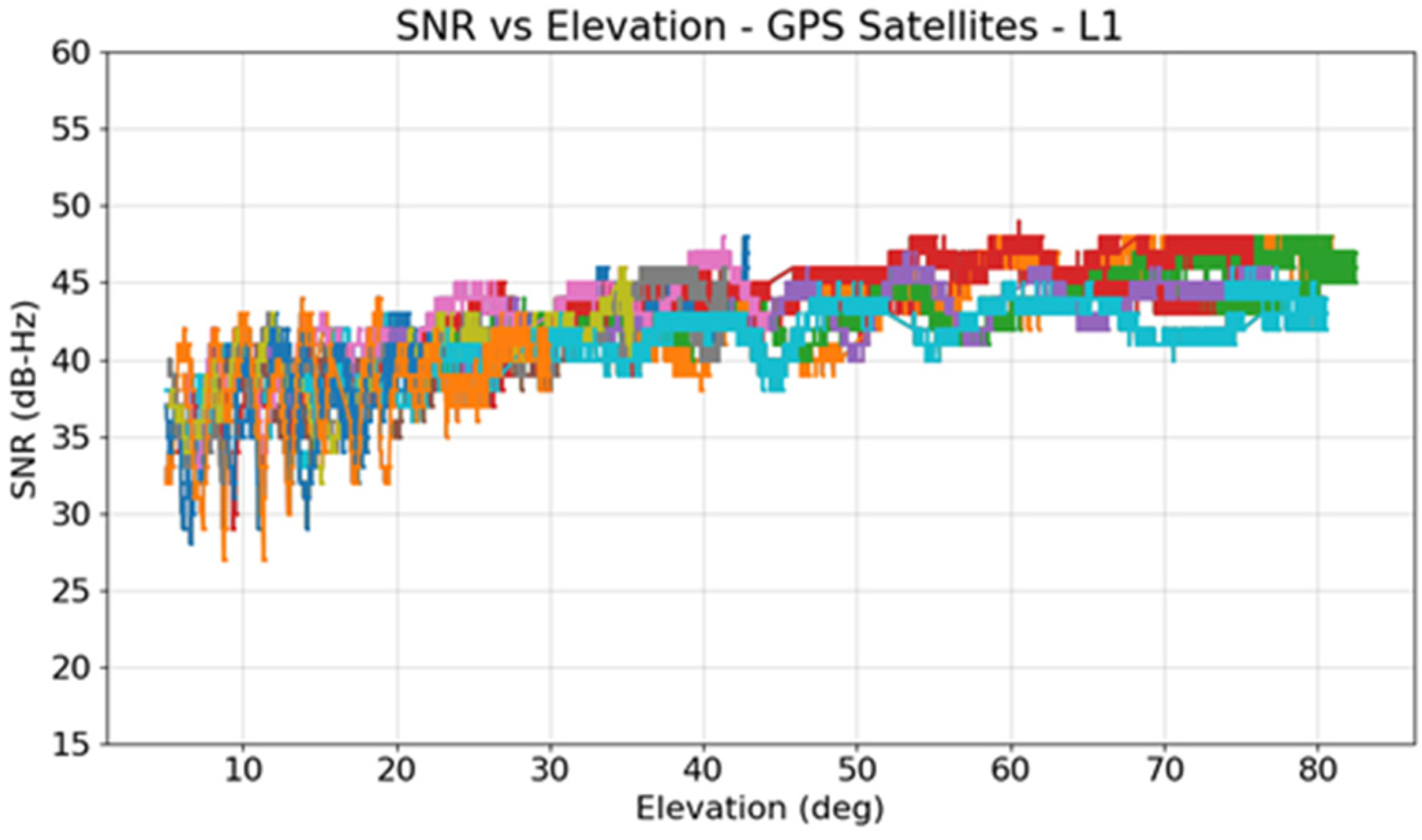
3. Static Tests
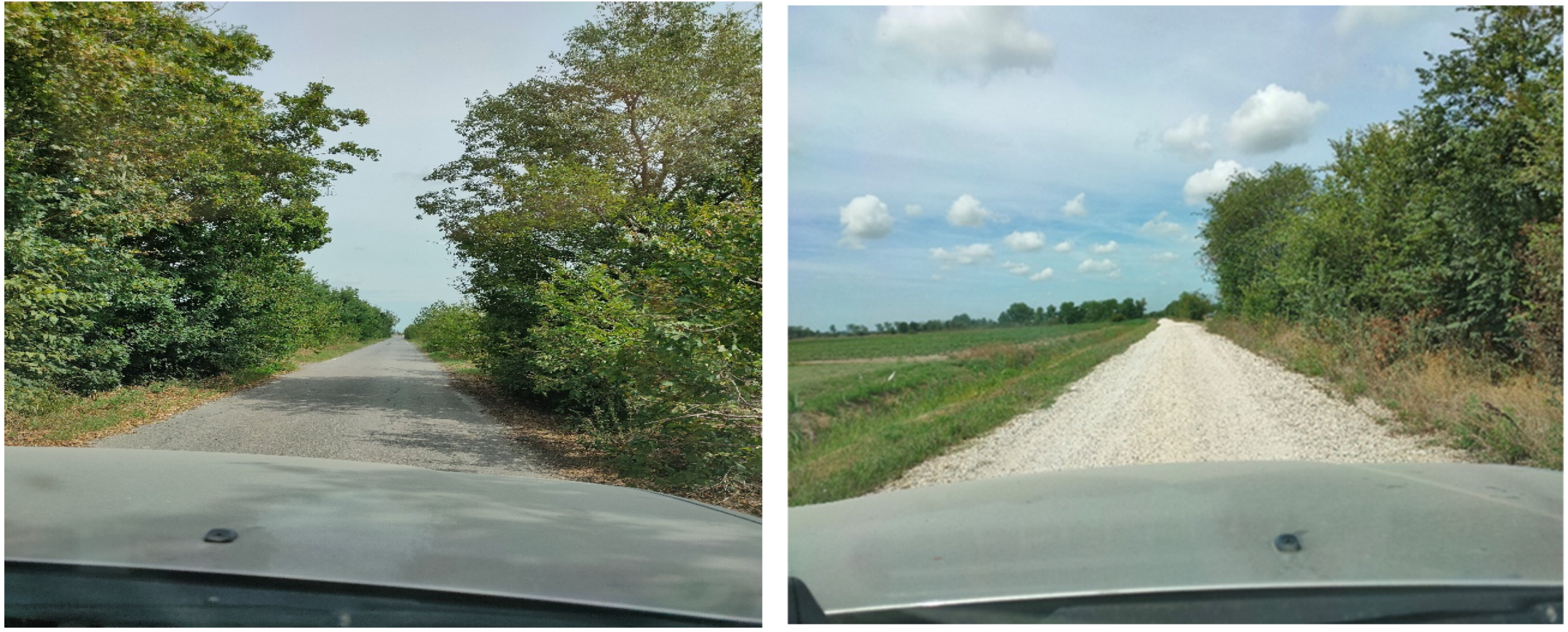
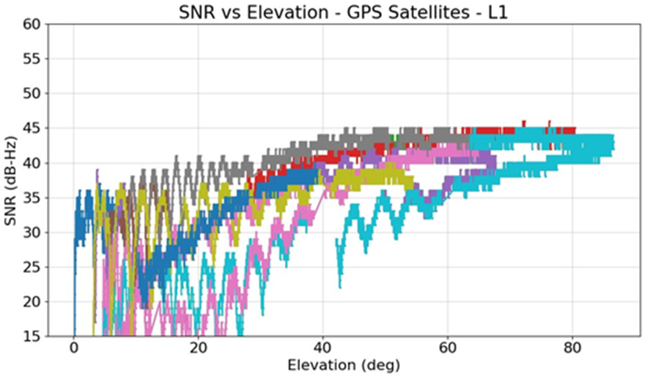
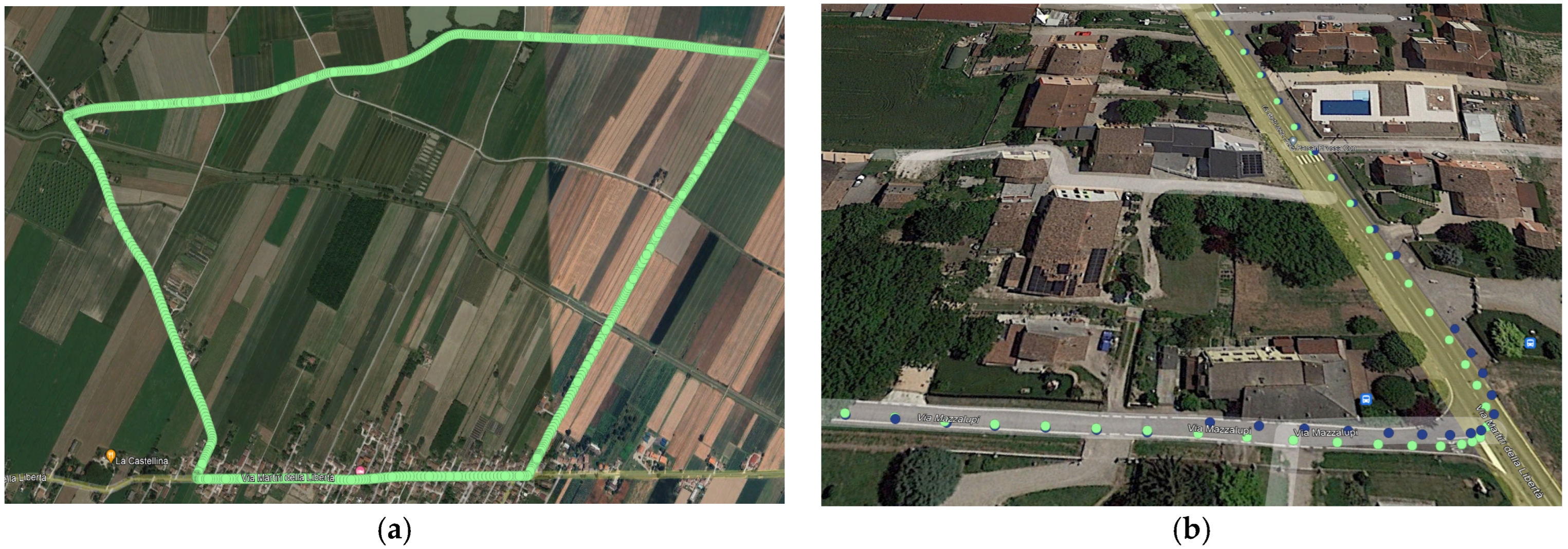
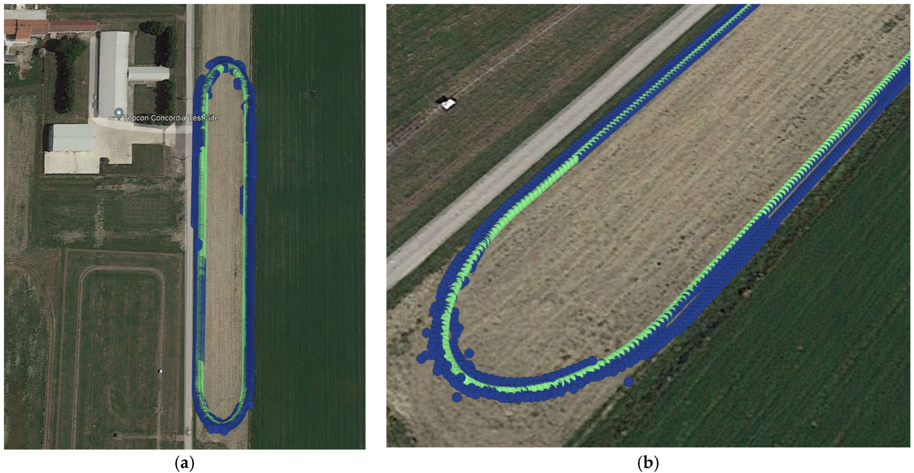
4. Kinematic Tests
5. RTK Tuning Discussion
- Satellite elevation mask;
- C/N0 cut-off values for the different signals;
- Observation weighting approach;
- Code and phase noise.
6. Conclusions
Author Contributions
Funding
Institutional Review Board Statement
Informed Consent Statement
Data Availability Statement
Conflicts of Interest
References
- Odolinski, R.; Yang, H.; Hsu, L.; Khider, M.; Fu GDusha, D. Evaluation of the Multi-GNSS, Dual-Frequency RTK Positioning Performance for Recent Android Smartphone Models in a Phone-to-Phone Setup. In Proceedings of the 2024 International Technical Meeting of The Institute of Navigation, Long Beach, CA, USA, 23–25 January 2024; pp. 42–53. [Google Scholar] [CrossRef]
- Shinghal, G.; Bisnath, S. Conditioning and PPP processing of smartphone GNSS measurements in realistic environments. Satell. Navig. 2021, 2, 10. [Google Scholar] [CrossRef] [PubMed]
- Glaner, M.F.; Weber, R. Breaking the One-Meter Accuracy Level with Smartphone GNSS Data. Eng. Proc. 2023, 54, 16. [Google Scholar] [CrossRef]
- Li, Z.; Wang, L.; Wang, N.; Li, R.; Liu, A. Real-time GNSS precise point positioning with smartphones for vehicle navigation. Satell. Navig. 2022, 3, 19. [Google Scholar] [CrossRef]
- Available online: https://mytopcon.topconpositioning.com/support/products/pg-f1 (accessed on 25 March 2025).
- Available online: https://www.taoglas.com/product/allband-gnss-high-precision-patch-antenna/ (accessed on 25 March 2025).
- Available online: https://mytopcon.topconpositioning.com/support/products/hiper-vr (accessed on 25 March 2025).


| Base | Samples | TTFF [s] | Fix % | Horizontal Accuracy [m] | Vertical Accuracy [m] | Horizontal Precision [m] | Vertical Precision [m] |
|---|---|---|---|---|---|---|---|
| CN09 | 28,571 | 12 | 99.9 | 0.010 | 0.011 | 0.006 | 0.006 |
| CGU2 | 28,571 | 14 | 99.9 | 0.013 | 0.014 | 0.009 | 0.010 |
| GUAS | 28,571 | 64 | 99.7 | 0.040 | 0.034 | 0.016 | 0.034 |
| Base | Samples | TTFF [s] | Fix % | Horizontal Accuracy [m] | Vertical Accuracy [m] | Horizontal Precision [m] | Vertical Precision [m] |
|---|---|---|---|---|---|---|---|
| CN09 | 27,741 | 28 | 99.5 | 0.011 | 0.016 | 0.008 | 0.015 |
| CGU2 | 27,741 | 29 | 95.9 | 0.013 | 0.020 | 0.012 | 0.020 |
| GUAS | 27,741 | 205 | 91.1 | 0.051 | 0.043 | 0.026 | 0.052 |
| Base | Samples | TTFF [s] | Fix % | Horizontal Precision [m] | Vertical Precision [m] |
|---|---|---|---|---|---|
| CN09 | 9560 | 28 | 97.6 | 0.020 | 0.037 |
| CGU2 | 9560 | 29 | 95.9 | 0.046 | 0.048 |
| GUAS | 9560 | 175 | 91.3 | 0.090 | 0.134 |
| TTFF [s] | FIX % | TTFF Reference [s] | Fix % (Reference) | |
|---|---|---|---|---|
| Car (inside) | 49 | 75.34 | 0 | 97.76 |
| Car (outside) | 0 | 78.5 | 3 | 98.34 |
| Tractor | 41 | 81.95 | 1 | 99.9 |
Disclaimer/Publisher’s Note: The statements, opinions and data contained in all publications are solely those of the individual author(s) and contributor(s) and not of MDPI and/or the editor(s). MDPI and/or the editor(s) disclaim responsibility for any injury to people or property resulting from any ideas, methods, instructions or products referred to in the content. |
© 2025 by the authors. Licensee MDPI, Basel, Switzerland. This article is an open access article distributed under the terms and conditions of the Creative Commons Attribution (CC BY) license (https://creativecommons.org/licenses/by/4.0/).
Share and Cite
Zanini, F.; Susi, M.; Losi, G.; Nikitin, D. Real-Time Kinematic Positioning Using Multi-Frequency Smartphone Measurements. Eng. Proc. 2025, 88, 23. https://doi.org/10.3390/engproc2025088023
Zanini F, Susi M, Losi G, Nikitin D. Real-Time Kinematic Positioning Using Multi-Frequency Smartphone Measurements. Engineering Proceedings. 2025; 88(1):23. https://doi.org/10.3390/engproc2025088023
Chicago/Turabian StyleZanini, Francesco, Melania Susi, Gabriele Losi, and Dmitry Nikitin. 2025. "Real-Time Kinematic Positioning Using Multi-Frequency Smartphone Measurements" Engineering Proceedings 88, no. 1: 23. https://doi.org/10.3390/engproc2025088023
APA StyleZanini, F., Susi, M., Losi, G., & Nikitin, D. (2025). Real-Time Kinematic Positioning Using Multi-Frequency Smartphone Measurements. Engineering Proceedings, 88(1), 23. https://doi.org/10.3390/engproc2025088023