Proceeding Paper

Development of Proportional-Integral-Derivative Based Self-Balancing Robot Using ESP32 for STEM Education †

Department of Industrial Design, Ming Chi University of Technology, New Taipei 24301, Taiwan
Presented at the 2024 IEEE 6th Eurasia Conference on IoT, Communication and Engineering, Yunlin, Taiwan, 15–17 November 2024.
Eng. Proc. 2025, 92(1), 24; https://doi.org/10.3390/engproc2025092024
Published: 27 April 2025
(This article belongs to the Proceedings of 2024 IEEE 6th Eurasia Conference on IoT, Communication and Engineering)

Abstract

:
A STEM education provides students with a friendly and efficient environment for learning science, technology, engineering, and math. According to the needs of STEM programs and activities, humanoid, biped, and quadruped robots have been developed. Those robots are used as a learning tool supporting students in exploring the principles and theory of robotics and their related applications. In addition, those robots adapt open sources to provide free instructions for the students to build their own low-cost robots. To enhance the effects, a low-cost, two-wheel robot was created in this study. Unlike other robots, two-wheel robots usually require a gyroscope sensor and a motion controller to keep them balanced. The developed robot is an integrated system including hardware and software. Its hardware consists of an ESP32 microcontroller, a pair of DC motors, a gyroscope sensor MPU6050, and a driver for DC motors. The robot receives signals “angle” from the gyroscope, and then depends on the PID approach to drive the DC motors precisely in order to achieve balanced and smooth motions. The results of this study present the design of the robot, sensor calibration methods, and proportional-integral-derivative tuning.

1. Introduction

Many countries are upgrading their industries to Industry 4.0. According to the trend of Industry 4.0, automation and data exchange, cyber-physical systems, the Internet of Things (IoT), cloud computing, and artificial intelligence (AI) have been developed and used widely. They are also introduced to update the current industrial environment to let their industries satisfy the needs of Industry 4.0. In manufacturing, the smart factory promotes the current industry to the next level. Robots play an important role in the smart factory.
Therefore, we developed a low-cost robot for young students to learn robotics efficiently. The two-wheel robot showed performance in energy efficiency, compact design, and agile movement compared with other types of robots. The two-wheel robot can stand and move without assistance. The robot can balance and demonstrate complicated control theory in STEM activities. The robot was built using a 3D printer. ESP32 and MPU6050 were used for a proportional-integral-derivative (PID) controller. The created robot in this study can be used in a STEM education and related activities.

2. Literature Review
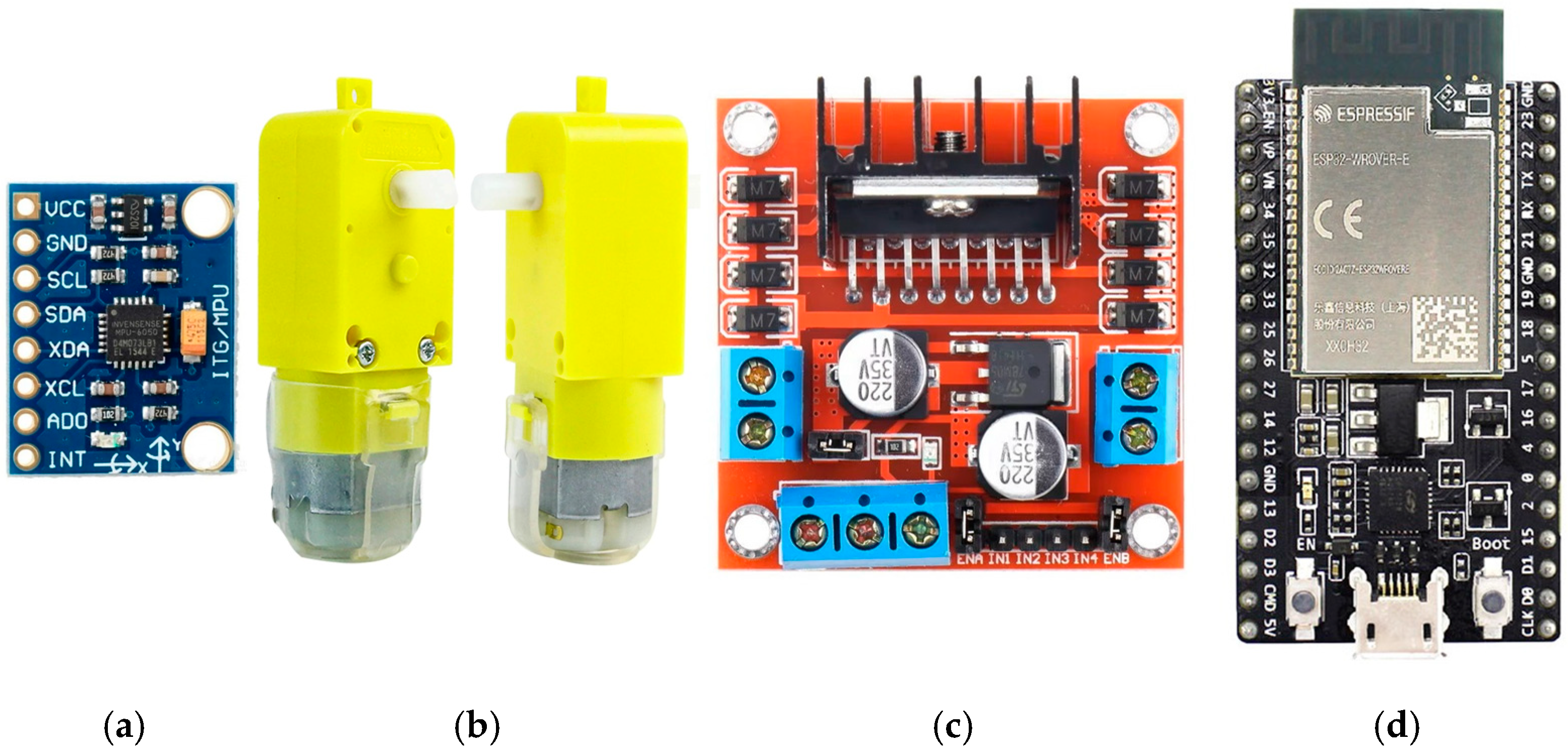
STEM stands for science, technology, engineering, and math, which are foundation of Industry 4.0. Unfortunately, most primary and high school students do not learn those disciplines well. Therefore, it is necessary to promote friendly teaching approaches like do-it-yourself (DIY) activities or digital learning tools [1,2]. For example, introducing cheap robots like Otto DIY into STEM programs had presented many successful stories about an efficient learning [3,4]. Many open-source robots and development kits are available to support young students to build their robots based on their needs.
According to the need, we developed a two-wheel robot for such purposes. The two-wheel robot contacts the ground with two points only. It is impossible to let the robot stand independently. The rule of the inverted pendulum was introduced to maintain the robot’s balance [5]. The two-wheel robot usually depends on a controller to keep itself upright position on the ground. Arduino was the common micro-controller selected for the robot, because it is an easy-to-use micro-controller [6]. To ensure the robot’s walk and functionality, a gyroscope sensor was also used [7].
The two-wheel robot employed a controller to steer wheels for rotations and maintain the upright position. A gyroscope sensor measures the tilt angle and sends signals to the PID controller by calculating the velocity and the rotation angle [8]. The PID controller is widely used in a closed-loop and feedback mechanism of control systems [9]. After installing the PID controller, it is still need a process for obtaining fine-tuned PID parameters which ensures the two-wheel robot’s smooth movement [10]. Except for the PID approach, the model predictive control (MPC) and fuzzy control were also applied to balance the two-wheel robot [11,12,13]. An all-terrain robot, called wheel-legged robot, was developed recently [14]. It is capable of traveling quickly in a flat road environment, and also moving swiftly in a bumpy road environment. This robot also requires a balancing mechanism, same as the two-wheel robot. therefore, this study attempts to develop a two-wheel robot to support students to explore the related technologies and knowledge of self-balance mechanism.

3. Hardware

The components of the robot included a motion sensor, a pair of DC motors, a motor driver, and a microcontroller (Figure 1). The functions and features of the components are described as follows.

3.1. Motion Tracking Sensor

The motion tracking sensor is capable of sensing object movement. The sensor was used to monitor the real-time orientations of the robot, as the controllers relied on the orientations to find appropriate movements and keep the robot in the upright position. The MPU6050 was used as an inertial measurement unit (IMU). A 3-axis gyroscope and 3-axis acceleration sensor were used. All components were connected to 5-voltage power through a serial clock line (SCL) and a serial data line (SDA) for Inter-Integrated Circuit (I2C) communication. This sensor is often connected with the micro-controllers like Arduino and Raspberry pi. The libraries are available for easy programming.

3.2. DC Gear Motors

The DC gear motor was used to steer the robot wheels in the forward or backward direction. A cheap and low-torque DC motor was used to drive robot wheels. A yellow gearbox part with a ratio of 1:120 was introduced to generate a high torque.

3.3. Motor Driver

The motor driver is an interface between a microcontroller and a gear motor. It controls electronic motors such as rotation speed and direction. The L298N motor drive is the most used and cheap one. It has a dual H-bridge motor driver IC to control DC and stepper motors in robotics and automation applications. It processes pulse width modulation (PWM) signals enabling speed control of the motors.

3.4. Microcontroller
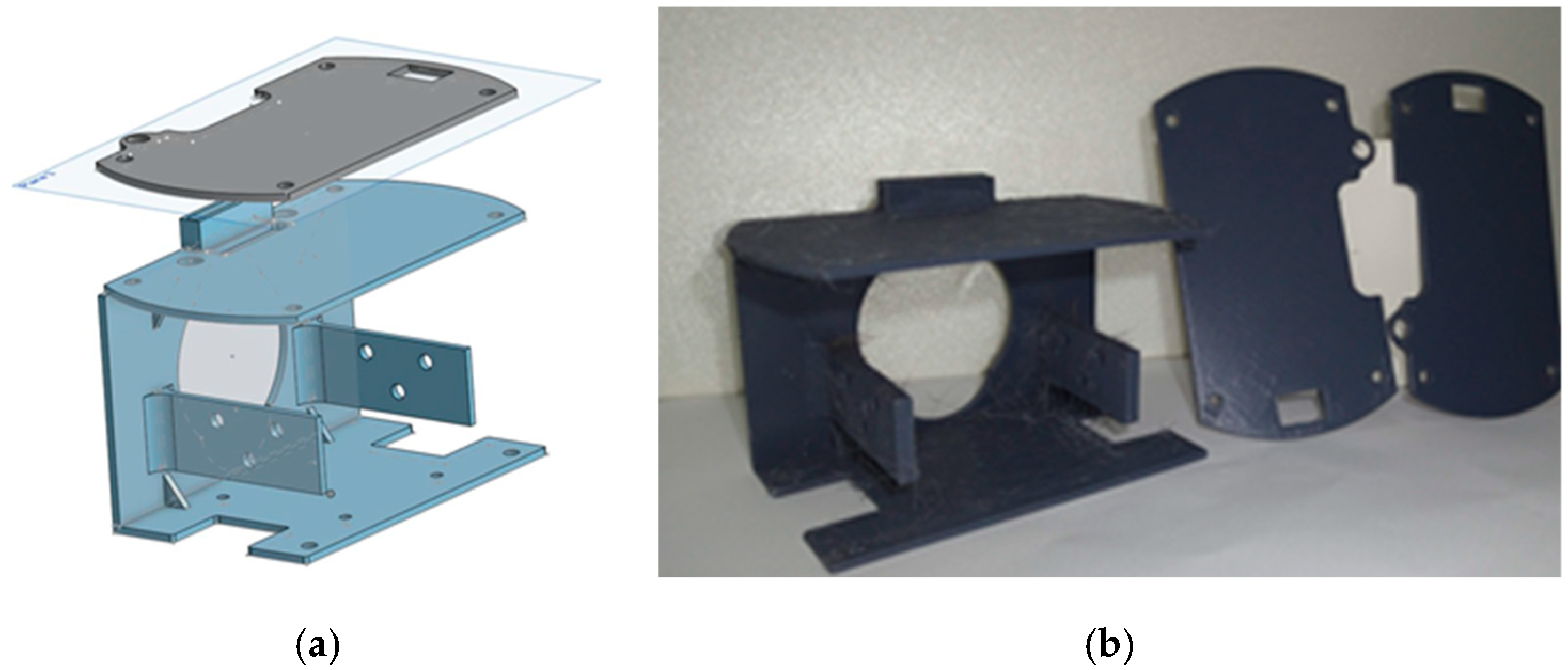
The microcontroller called ESP32 is the core electronic device of the robot. It features high-resolution analog-to-digital converters (ADC) and digital-to-analog converters (DAC) and has wide range of I/O pins, including digital, analog, PWM, SPI, I2C, and UART. It allows the robot to cooperate with sensors, steer actuators, process sensor signals, apply PID control algorithm, and execute robot routines. It supports Wi-Fi and Bluetooth, so it has great potential in developing wireless products and IoT applications.

3.5. Robot Frame

The robot frame was used to contain the components together. Its virtual model was created by computer-aided design software, and its physical model was printed by a 3D printer. The material used was polylactic acid, which is a cheap and green material. Figure 2a shows the CAD model of the robot frame, and Figure 2b shows the printed parts. The robot wheels were purchased from a toy store.

4. Robot System

The robot integrates sensors, actuators, and firmware. The electronic components included an MPU sensor and two gear motors, L298N and ESP32. ESP32 was the most important part of the robot system as it received the signals from MPU6050. The PID controller converted signals from MPU6050 to actuator signals to allow the two-wheel robot to stand. Arduino IDE was used to program ESP32.

4.1. PID Controller

The PID controller is frequently applied in the automation industry. Figure 3 shows the control system of the robot based on the PID control. The system had a closed-loop system. In the figure, C(s) presents the PID control function, P(s) is the robot function, u is the output generated by P(s), y is the output measured by the robot, r is the desired output, y and r are the tilt angles of the robot, and e presents the tracking error, the difference between the desired output and real output.
The output equation u(t) of the PID controller is (1). The Kp, Ki, and Kd are proportional, integral, and derivative gains. Those gains are defined in a tuning process.
u t = K p · e t + K i e t d t + K d d e ( t ) d t

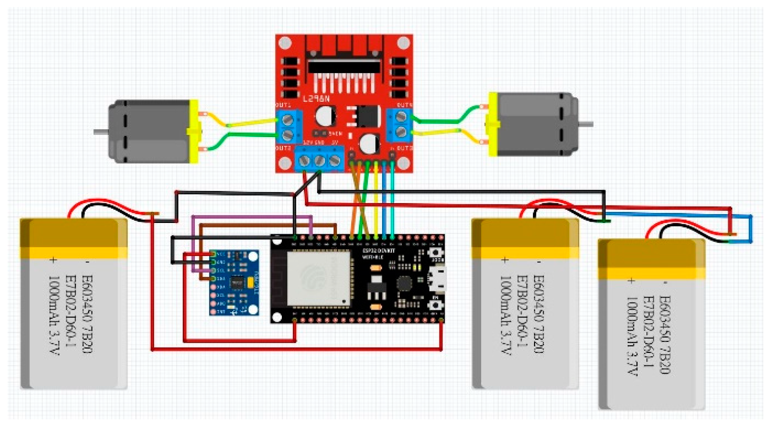
4.2. Electronic Device Wiring

Figure 4 shows the electronic schematic of the two-wheel robot. L298N drove two DC motors and provided power to DC motors. Its pins ENA, ENB, N1, N2, N3, and N4 were connected to GIOP4, 5, 16, 17, 18, and 19 of ESP32, respectively. The gyroscope sensor, MPU6050, was operated on I2C communication, so its pin SCL and SDA were connected to GIOP 22 and 21 of ESP32. Considering stable signals sent by MPU6050, the powers for DC motors, MPU6050, and ESP32 were separated. The DC motors were powered by a 7.4 V Lithium battery, ESP32 was powered by a 5 V Lithium battery, and ESP32 and MPU6050 were powered by a 3.3 V Lithium battery.

4.3. Firmware and PID Tuning

The robot was controlled by the PID controller to balance and keep the upright position. Open-source libraries were introduced, such as the Arduino libraries, PID_v1 and I2Cdev. Arduino IDE provides the libraries to pregame the gyroscope sensor and DC motors related events. After the firmware was created, the gyroscope sensor and PID were calibrated.
  • Gyroscope sensor calibration: After the robot hardware was installed completely, a sensor calibration is needed. The MPU6050 sensor was calibrated using calibration codes available on the Internet. This calibration guarantees that the sensor provides accurate and correct title angle to the robot micro-controller for further application.
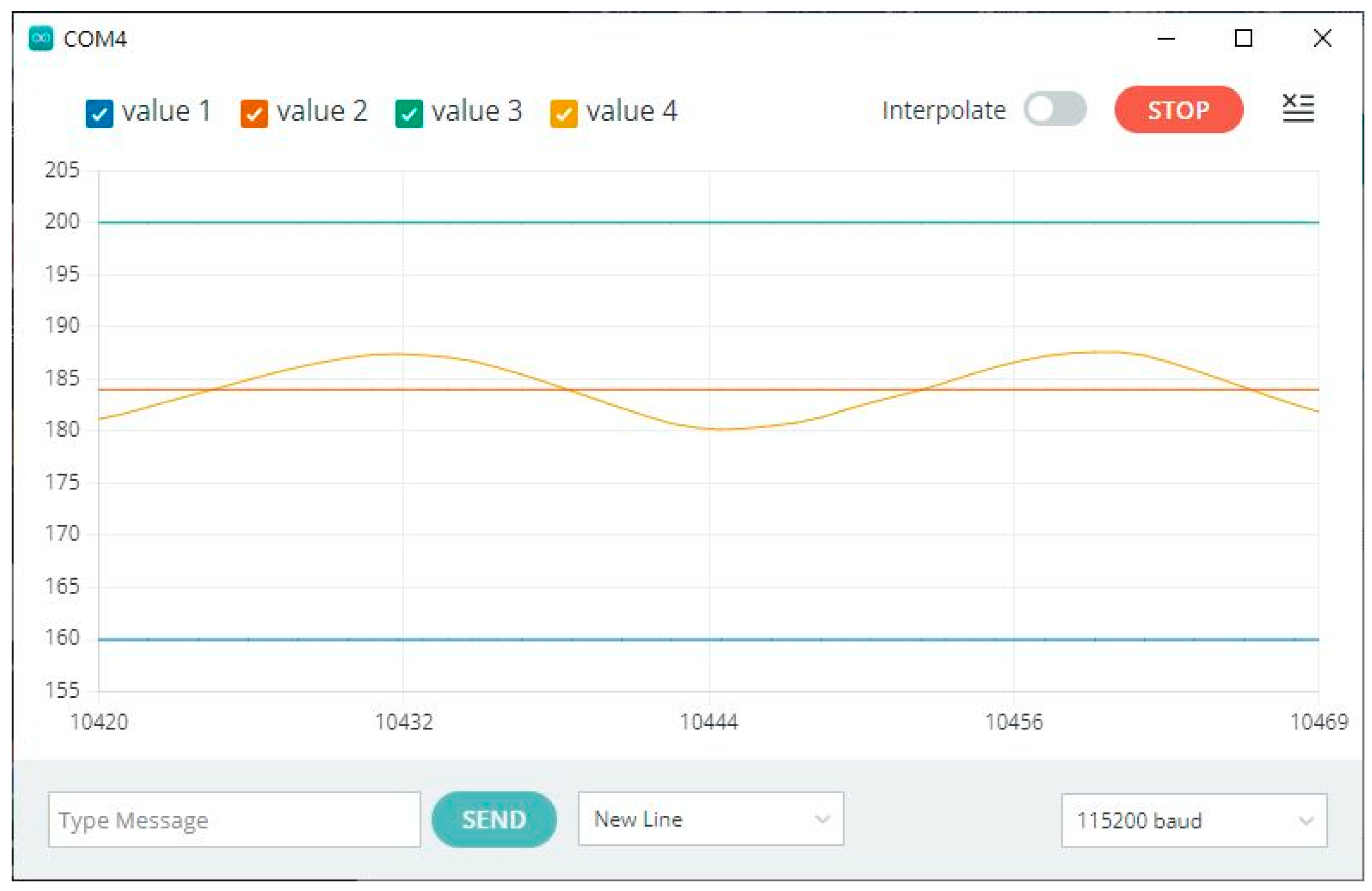
  • PID tuning: The Ziegler-Nichols tuning method, Cohen-Coon tuning method, Kappa-Tau tuning method, Lambda tuning method, and Trial and Error method are used for PID tuning. This study used the Trial and Error method to obtain proportional, integrated, and derivative gains. The method gained the proportional gain first, and then integrated and derivative gains. This tuning process will be arranged to be a part of STEM activity. Students can learn PID control theory via adjusting PID parameters and testing the robot personally.

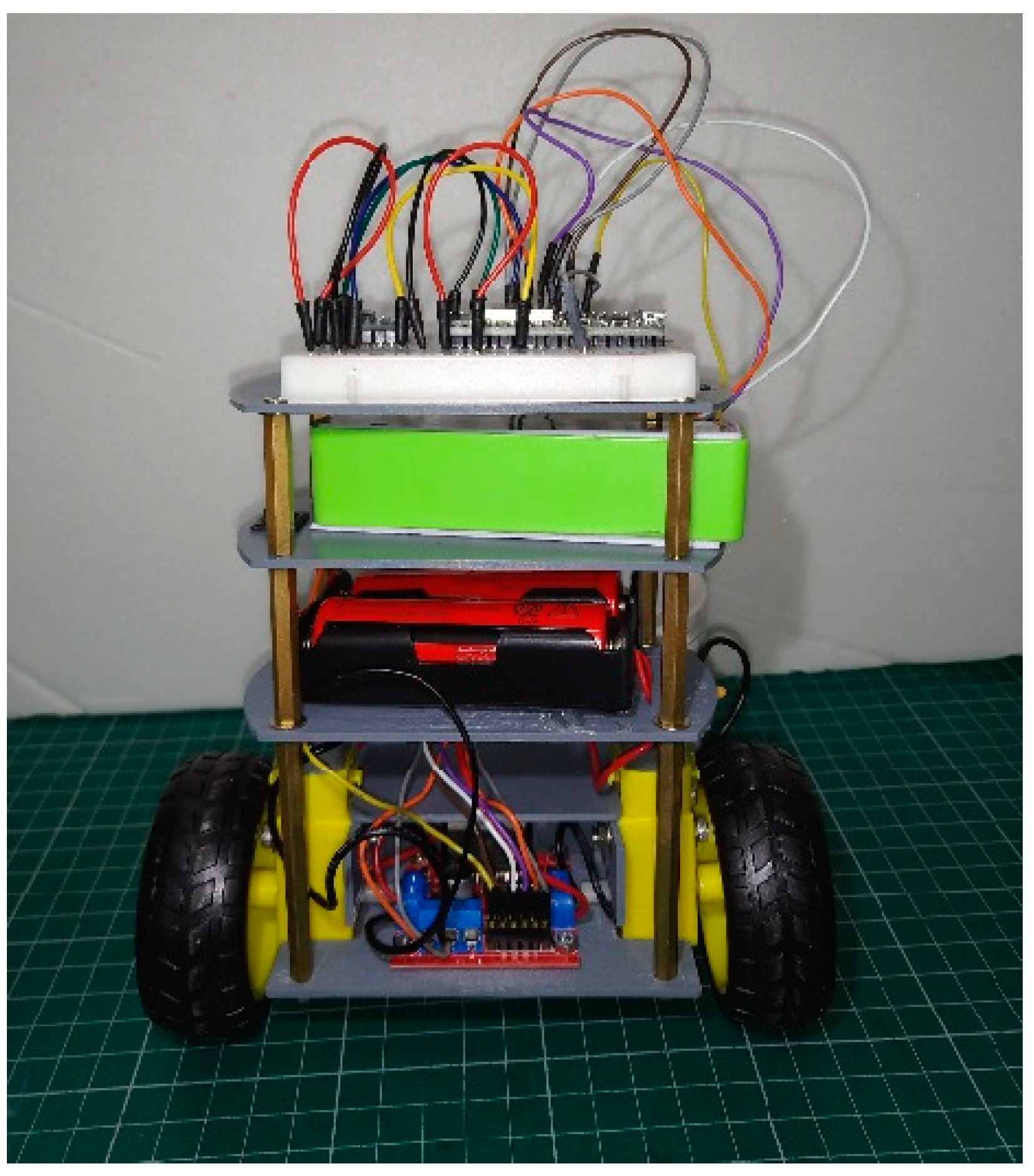
5. Results and Conclusions

Figure 5 shows the developed self-balancing two-wheeled robot. Since this robot was designed for a STEM education, a breadboard was installed on its top to support electronic device installation. There were two power sources, one for supporting the MPU6050 and micro-controller, and the other one for supporting DC motors. This power separation guarantees that the MPU6050 is capable of providing stable signals to the micro-controller.
In this study, the desired output was 184, and the output measured by MPU6050 was between 180 and 188 (see Figure 6). In STEM activities, the robot can be used to assist teachers in demonstrating the principles of robot control theories and robotics. In the future, the robot needs to be improved for different uses.

Funding

This research received no external funding.

Institutional Review Board Statement

Not applicable.

Informed Consent Statement

Not applicable.

Data Availability Statement

No new data were created or analyzed in this study. Data sharing is not applicable to this article.

Conflicts of Interest

The author declares no conflict of interest.

References

  1. Afari, E.; Khine, M.S. Robotics as an Educational Tool: Impact of Lego Mindstorms. Int. J. Inf. Educ. Technol. 2017, 7, 6. [Google Scholar] [CrossRef]
  2. Barker, B.S. Robots in K-12 Education: A New Technology for Learning: A New Technology for Learning; Information Science Reference: Hershey, PA, USA, 2012. [Google Scholar]
  3. Hsieh, C.T. Developing Programmable Robot for K12 STEAM Education. In Proceedings of the Eighth International Multi Conference on Engineering and Technology Innovation 2019, Kaohsiung, Taiwan, 15–19 November 2019. [Google Scholar]
  4. Hsieh, C.-T. Low Cost Quadrupedal Robots for the STEM Education. In Proceedings of the 17th International Conference on Automation Technology (Automation 2020), Hualien, Taiwan, 12–14 November 2020. [Google Scholar]
  5. Grasser, F.; D’Arrigo, A.; Colombi, S.; Rufer, A.C. JOE: A mobile, inverted pendulum. IEEE Trans. Ind. Electron. 2002, 49, 107–114. [Google Scholar] [CrossRef]
  6. Pajpach, M.; Haffner, O.; Kucera, E.; Drahos, P. Low-Cost Education Kit for Teaching Basic Skills for Industry 4.0 Using Deep-Learning in Quality Control Tasks. Electronics 2022, 11, 230. [Google Scholar] [CrossRef]
  7. Hartono, R.; Kim, S.B.; Kalend, P.T.A.; Baik, N.K.; Shin, K.J. Design of Self-balancing Model-size Electrical Motorbike Robot Using Control Moment Gyroscope. Sens. Mater. 2023, 35, 347–363. [Google Scholar] [CrossRef]
  8. Tomasic, T.; Demetlika, A.; Crnekovic, M. Self-Balancing Mobile Robot Tilter. Trans. FAMENA 2012, 36, 23–32. [Google Scholar]
  9. Bennett, S. Nicholas Minorsky and the automatic steering of ships. IEEE Control Syst. Mag. 1984, 4, 10–15. [Google Scholar] [CrossRef]
  10. Huba, M.; Chamraz, S.; Bistak, P.; Vrancic, D. Making the PI and PID Controller Tuning Inspired by Ziegler and Nichols Precise and Reliable. Sensors 2021, 21, 6157. [Google Scholar] [CrossRef] [PubMed]
  11. Azimi, M.M.; Koofigar, H.R. Model predictive control for a two wheeled self balancing robot. In Proceedings of the 2013 First RSI/ISM International Conference on Robotics and Mechatronics (ICRoM), Tehran, Iran, 13–15 February 2013; pp. 152–157. [Google Scholar] [CrossRef]
  12. Junfeng, W.; Wanying, Z. Design of fuzzy logic controller for two-wheeled self-balancing robot. In Proceedings of the 2011 6th International Forum on Strategic Technology, Harbin, China, 22–24 August 2011; Volume 2, pp. 1266–1270. [Google Scholar] [CrossRef]
  13. Simon, J. Fuzzy Control of Self-Balancing, Two-Wheel-Driven, SLAM-Based, Unmanned System for Agriculture 4.0 Applications. Machines 2023, 11, 467. [Google Scholar] [CrossRef]
  14. Zhang, A.; Zhou, R.; Zhang, T.; Zheng, J.; Chen, S. Balance Control Method for Bipedal Wheel-Legged Robots Based on Friction Feedforward Linear Quadratic Regulator. Sensors 2025, 25, 1056. [Google Scholar] [CrossRef] [PubMed]
Figure 1. (a) MPU6050, (b) DC gear motor, (c) L298N motor driver, and (d) ESP32.
Engproc 92 00024 g001
Figure 2. (a) CAD Models; (b) PLA frame.
Engproc 92 00024 g002
Figure 3. Closed-loop control system of robot.
Engproc 92 00024 g003
Figure 4. Wiring self-balancing robot.
Engproc 92 00024 g004
Figure 5. Self-balancing two-wheel robot.
Engproc 92 00024 g005
Figure 6. Output of robot movements.
Engproc 92 00024 g006
Disclaimer/Publisher’s Note: The statements, opinions and data contained in all publications are solely those of the individual author(s) and contributor(s) and not of MDPI and/or the editor(s). MDPI and/or the editor(s) disclaim responsibility for any injury to people or property resulting from any ideas, methods, instructions or products referred to in the content.

