Concept Paper

Phasor Measurement Unit Assisted Inverter—A Novel Approach for DC Microgrids Performance Enhancement

Department of Electrical Engineering and Computer Science, Alabama A&M University, Huntsville, AL 35762, USA
Electricity 2021, 2(3), 330-341; https://doi.org/10.3390/electricity2030020 (registering DOI)
Submission received: 17 May 2021 / Revised: 5 July 2021 / Accepted: 6 July 2021 / Published: 24 August 2021

Abstract

:
DC microgrids are set to change the landscape of future energy markets. However, a wide-scale deployment faces three major issues: initial synchronization of microgrid with the utility grid, slip management during its operation, and mitigation of distortions produced by the inverter. This paper proposes a Phasor Measurement Unit (PMU) Assisted Inverter (PAI) that addresses these three issues in a single solution. The proposed PAI continually receives real-time data from a Phasor Measurement Unit installed in the distribution system of a utility company and keeps constructing a real-time reference signal for the inverter. A well-constructed, real-time reference signal plays a vital role in addressing the above issues. The results show that the proposed PAI is 97.95% efficient.

1. Introduction

Community microgrids have emerged as an alternative to address the rising societal demands for electric infrastructures. They are not only economical and environmentally friendly but also promise a long list of ambitious goals, including, premium reliability, superior power quality, improved sustainability, and smooth integration of renewable energy [1]. They are typically capable of operating in islanded or grid-connected mode. Though the technology is proven, it faces the following three major technical challenges.

1.1. Initial Synchronization of DC Microgrid with the Utility’s AC Grid

Synchronization is the process of connecting an incoming microgrid with the running utility grid. In the case of a DC microgrid, it first requires conversion of DC to AC and then matching the AC signal characteristics (i.e., voltage, phase, and frequency) to that of a utility grid’s AC signal characteristics [2]. Mismatch of any of these characteristics during the initial connection or during the grid-connected operation makes the microgrid incapable of delivering power to a utility grid. In traditional grids, synchronization is achieved by controlling the excitation and the governor’s speed. However, in DC microgrids, synchronization is achieved by controlling inverter functions, such as (a) a reference sine waveform signal, (b) input voltage, and (c) shape and pattern of pulse width in a Pulse Width Modulator (PWM) [3]. The literature shows that for synchronization, the frequency controller [4], the excitation controller [5], nonlinear controllers [6], and Phase-Locked Loop (PLL) techniques [7,8] are used; however, they have shortcomings one way or the other. From the above references, we conclude that most techniques fail to track the phase and frequency of grid voltage during grid faults and other adverse operating conditions. From the above references, we also learn that a reference signal that could adapt its phase and frequency according to the real-time operating conditions will play a key role in initial synchronization.

1.2. Slip Management during Connected Mode Operation

Slips, also known as frequency oscillations, result during the grid-connected operation when the frequency of the microgrid is not closely matched with that of the utility grid. If a slip is not managed, oscillations will be produced, and the system may fall out of synchronization and fail to deliver the power to the utility grid. Literature shows that the inverter’s output frequency is a function of the reference signal frequency applied to the PWM of the inverter; therefore, Slip can be managed by controlling the frequency of the reference signal [3]. Reference [9] proposes the frequency control method based on zero-crossing; however, poor performance is reported by the authors themselves. To enhance the performance, a modified zero-crossing method is proposed in [10], but it is compute-intensive. Reference [11] suggests a Discrete Fourier Transform (DFT)-based frequency measurement; however, DFT produces erroneous results during rapid frequency deviation as stated by [12]. Reference [13] presents frequency control by using PLL; however, the reliability is a challenge. Reference [14] suggests a controller, and [15] proposes a linear-time continuous system; however, both are vulnerable to system uncertainties. Reference [16] also presents a PLL-based synchronization approach with DQ power flow but only to cater for changing wind speed conditions for a nine-wind turbine system. From these references, we learn again that a reference signal that could adapt its frequency according to the load conditions is vital in slip management.

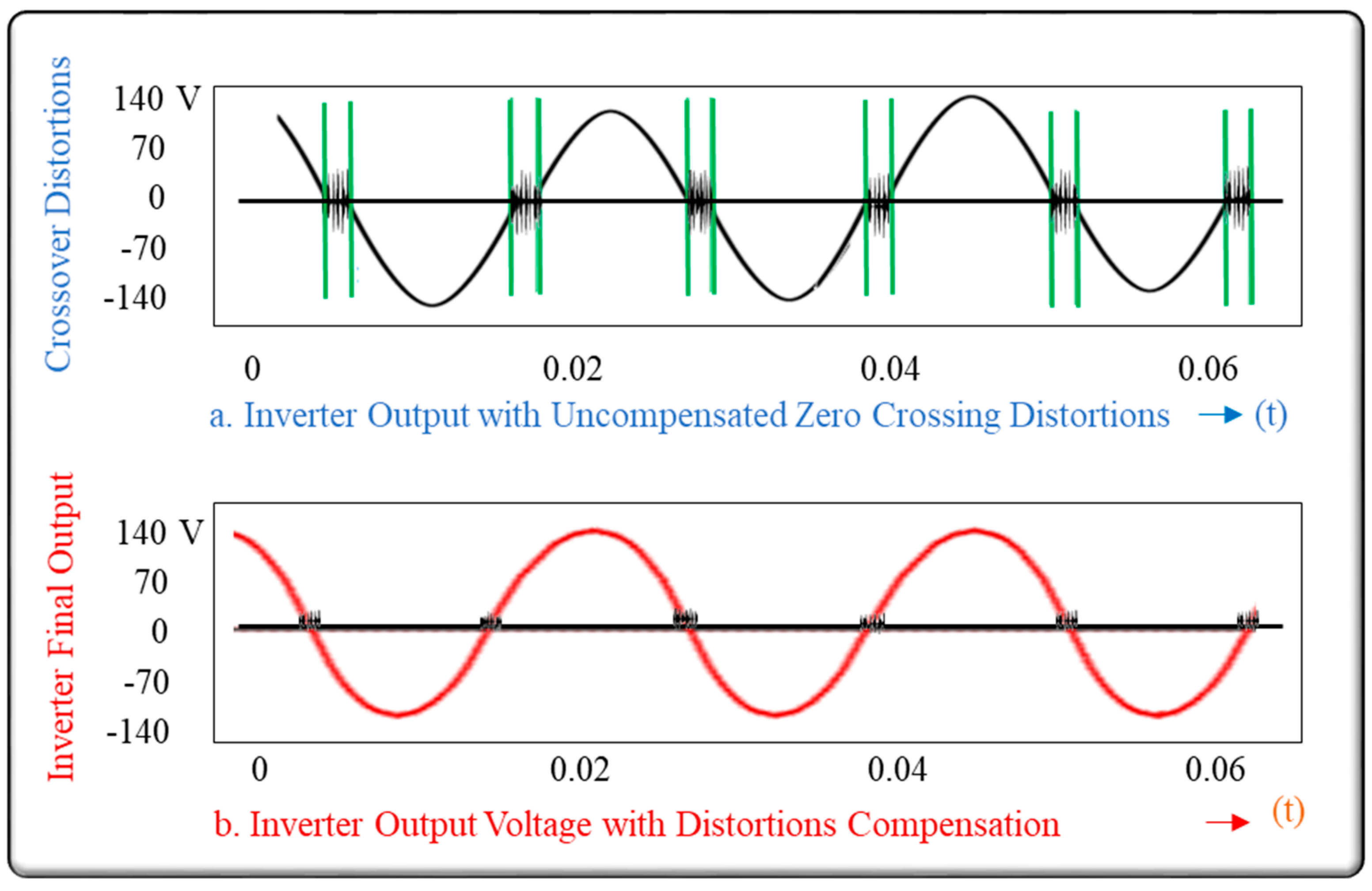
1.3. Production of Distortion-Free, Pure Sine Wave

DC microgrid uses an inverter to convert DC into AC. The inverter uses electronic switches such as Insulated Gate Bipolar Transistor (IGBT). The non-ideal characteristics of the IGBTs set a zero-current-clamping phenomenon that distorts the AC waveform each time it crosses zero voltage and hence called Zero Crossovers Distortions [16,17]. Compensation to these distortions is important to attain a pure sinusoidal waveform demanded by the AC utility grid. This requires the width of the PWM signal to be adjusted in each switching cycle. The pulse width is adjusted by adjusting the reference sine waveform signal [17]. Reference [18] that presents a survey of numerous solutions also establishes that PWM requires the direct adjustment of real-time pulse width in each switching cycle. To accomplish this task [19], suggests a Proportional Integral Controller, [20] uses a tri-carrier Sinusoidal PWM [21], presents a dead-time compensation scheme, and [22] proposes a Single-channel Time Analyzer for measuring the narrow pulse width of a pulse train. However, these techniques increase the complexity of the system. Reference [23] successfully compensates for voltage distortion, but the input signal includes narrow pulses, reference [24] presents a protection algorithm that ensures that no switch is turned on during the dead time, but the fifth, sixth, and seventh current harmonics are generated in the reference frame. Active-power, reactive-power, frequency, and voltage droop control are proposed in [25,26,27]; however, these are compute-intensive. Additionally, reference [28] designs a control of grid-side inverter, but it is limited only to a permanent magnet AC generator. From these references, we learn yet again that a reference signal that could adapt its frequency according to the load conditions is vital in mitigating zero crossovers distortions.
From the entire literature review we presented above, we infer that DC microgrids face three major technical problems, i.e., initial synchronization with the utility grid, instantaneous slip management during operation, and distortions produced by the inverter electronics. We conclude that: (i) almost all the approaches suggest that the reference signal, whose characteristics (magnitude, frequency, and phase angle) not only closely resemble that of the utility grid’s AC voltage characteristics but also continually adapt on a real-time basis according to the varying load conditions of the grid plays a vital role in addressing these three issues on the table.
Though numerous approaches address the above three challenges independently, there is not a single approach that addresses all the three challenges combined in one. We propose a new PMU Assisted Inverter (PAI) for a DC microgrid. We name it “PMU Assisted Inverter” because one of the integral components of it, named PMU Data Receiver, continually receives real-time PMU data about the utility grid’s AC voltage waveform characteristics (magnitude, frequency, and phase) from the nearest PMU installed in the utility company’s distribution system. PMU receives this data over IP based network via the Internet or wireless communication system, as shown in Figure 1. The PMU data receiver uses this data to construct a reference signal that continually adapts itself on a real-time basis to closely mimic the AC grid voltage. The reference signal so generated is fed to the inverter. Since the reference signal adapts its characteristics continually according to the prevailing utility grid AC voltage, it assists in achieving the DC grid in initial synchronization, the slip management during grid-connected operation, and the distortion mitigation triggered by the two transistor pairs used in the inverter during zero crossover.
The rest of the paper is divided into four sections. Section 2 presents the description, Section 3 is dedicated for discussion, and Section 4, the Conclusion, concludes the paper.

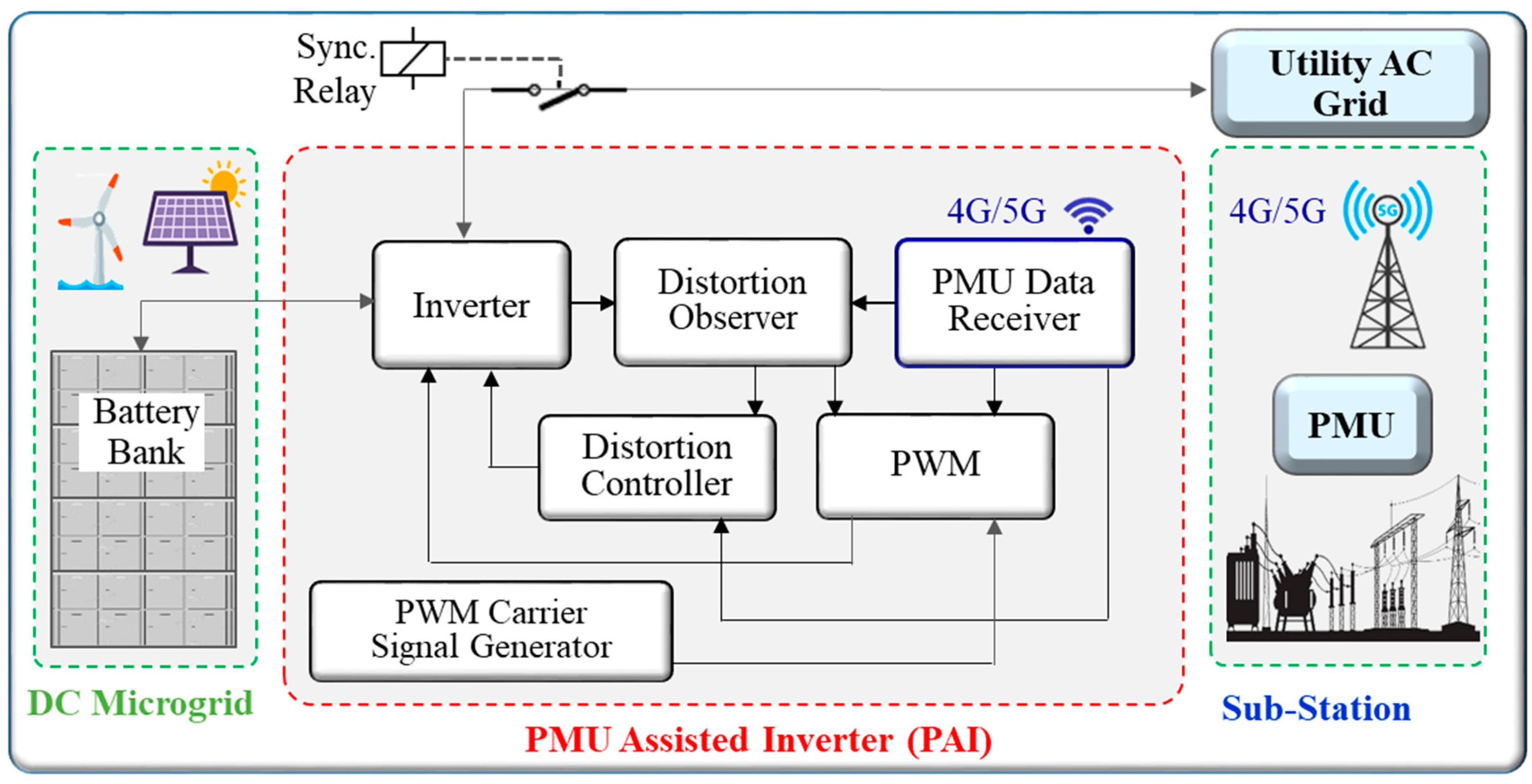
2. Description of Proposed Work

Figure 1 shows that the proposed architecture consists of a DC microgrid and a Phasor Measurement Unit Assisted Inverter (PAI). The DC microgrid normally operates in two modes: grid-connected mode and islanded mode and functions autonomously, as physical or economic conditions dictate. In the islanded mode, the battery banks may be charged by local renewable energy sources such as wind and solar, and in the connected mode, the battery banks may be charged by the main AC grid during off-peak hours. The need for charging the battery banks from the utility grid may arise under the following situations. The battery banks are charged from the utility grid when energy prices or the energy demand is low and discharged when energy prices or the energy demand is high during peak hours. This practice not only helps meet the energy demand during peak hours but also generates more revenue. Further, the need for battery bank charging may arise when the connected electrical vehicles have to be charged on a certain schedule, and local renewable energy sources are not enough to meet the connected EVs demand. The DC microgrid is shown in the green boundary in Figure 1.
The proposed PAI comprises of (i) Inverter Circuit, (ii) PMU Data Receiver, (iii) Pulse Width Modulator (PWM), (iv) Distortions Observer, and (v) Distortion Controller, as shown in the red boundary in Figure 1.
For grid-connected mode, the inverter takes input from the DC microgrid, a pulse width-modulated signal from the PWM, and a feedback signal from the distortion controller. In the Introduction section, we established that a reference signal that continually adapts itself on a real-time basis to closely mimic the AC grid voltage plays a vital role in initial synchronization, slip management, and distortions mitigation. Our PMU data receiver receives real-time PMU data about the grid’s voltage characteristics and constructs a reference signal. The characteristics of the reference signal not only closely resemble that of the utility grid’s AC voltage but also continually adapt in real-time according to the varying load conditions of the grid. Thus the inverter’s output AC voltage mimics the utility grid voltage making it ready for initial synchronization with the utility grid. When all the synchronization conditions are met, the DC microgrid is synchronized and connected to the utility grid. Synchronizing relays allow unattended synchronization of a DC microgrid with the utility grid. Synchroscopes or lamps may also be installed as a supplement to automatic relays for possible manual use.c
The PMU data receiver of PAI receives real-time PMU data, up to 120 measurements per second, about the utility grid’s real-time AC voltage waveform characteristics (magnitude, frequency, and phase) from the PMU data server. Historically, PMUs have been used to monitor transmission lines, and now, the smaller version of them is desired to be installed on distribution networks. The data from these PMUs will be collected either in the utility’s network server or cloud-based server. Utilities will be able to share this data sooner in the future with the approval of proper authority, e.g., NERC, FERC, TRE, etc., with customers, trusted third parties, Independent Service Providers (ISO) for value-added services, or universities for collaborative research. For our proof of concept, we used a MATLAB-based PMU simulator, which is explained in the next section.
The Zero Crossovers Distortions are triggered by the two transistor pairs used in the Inverter. The trigger comes from the delay between the turn-off of one transistor pair and the turn-on of its complement pair. Though crossover delay is kept as low as possible (between 1 and 2 μs), it can still cause large voltage distortions [29]. These distortions not only distort the quality of the voltage signal but also become the subject for causing “Slips.” To compensate for these distortions and, thereby, manage the slips, reference signal adjustments are required in each switching cycle [30]. We accomplish it by using the Distortion Observer and Distortion Controller that continually measure the amount of distortion “D,” compute the state average models for the inductor and capacitor and then adjusts Ldi/dt, CdVc/dt, and the pulse width. Thus, the PWM, the Distortion Observer, and the Distortion Controller that also receive the reference signal continually compare the inverter output AC voltage with the real-time reference voltage and make sure that the output signal is distortion-free and its characteristics are within the limits dictated by the PMU-aided reference signal. Such a distortion-free output AC signal helps avoid slips and keeps it tightly synchronized with the utility grid during the entire operation.
We used a simulator for the TMS320F28069 microcontroller to control the above process. This microcontroller from Taxes Instruments is capable of providing the Control Law Accelerator and the power of the C28x core. It provides highly integrated control. For more information, the datasheet of the product is available at [31]. The microcontroller runs the algorithm shown in the flowchart of Figure 2. All the steps in the algorithm make sure that the inverter output AC voltage mimics the utility grid voltage, it is ready for initial synchronization with the utility grid when all the other grid connectivity conditions are met, and that the distortions are controlled in each switching cycle on a real-time basis to avoid slips, and the inverter output is tightly synchronized with the utility grid during the entire operation. In Figure 2, “ε” represents the allowable limits of synchronization. According to reference [32], the allowable limits for synchronization are (i) voltage magnitudes difference of 5%, (ii) the frequencies difference of 0.2%, and (iii) the phase angles difference of 0.2% are allowable. If these conditions are met, initial synchronization proceeds.
Microcontrollers run embedded software code that is written in Simulink, and Optimization toolboxes integrated into MATLAB 9.8, released 2020, are used for the simulation of the PMU to execute the steps shown in the flowchart. The code is explained in Section 2, Simulation and Mathematical Analysis.

3. Discussion: Simulation and Mathematical Analysis

This section evaluates the performance of the PAI. For proof of the concept, we use a MATLAB-based PMU simulator that employs the PMU processing algorithm developed in [33] and customized to execute our approach, as shown in Figure 3. In the figure, the phasor estimation (Pn) is computed using Discrete Fourier Transform (DFT) with the sampling period (t), the sampling window (N), the frequency deviation (Δω), and the calibration factors. Frequency deviation (Δω = ωω0) is estimated in real-time because, in any power system operation, the frequency is never steady. This deviation may be small or large, depending on load fluctuation. Thus, the frequency estimation methodology plays a key role in producing real-time data that is used for the construction of the reference signal. Thus according to [34], Pn the phasor estimation is given by:
P n = { sin N ( ω ω 0 ) Δ t 2 Nsin ( ω ω 0 ) Δ t 2 } e j ( N 1 ) ( ω ω 0 ) Δ t 2
The key element in any PWM-based inverter is the frequency and phase of the reference signals. The PMU simulator output (PMUSim O/P) supplies these parameters to the PMU aided reference signal generator. The PMU reference signal generator uses these parameters and defines the duty cycle of the carrier pulses generated and thus the signal frequency of the output signal (that mimics the utility frequency).
The PWM carrier signal defines the sampling rate of DC to AC conversion. The higher the sampling rate, the more pulses per 60 Hz generated, and thus the purer the AC output becomes. By overcoming the crossover distortion, as explained below, we can use an 8 kHz sampling rate. The PWM output is then fed to the inverter. Appendix A provides simulation code for both the PWM and the inverter.
The mitigation of zero crossover distortions (also known as dead time effect, td.) is explained here. In the inverter circuit shown in Figure 4, two pairs of IGBT (Q1–Q4 and Q2–Q3) are used in Leg-A and Leg-B, respectively.
The outputs of the Leg-A and Leg-B are vao and vbo. Q1–Q4 and Q2–Q3 are switched synchronously in a diagonal way, and consequently, vbo = −vao. Therefore, the inverter output voltage vinv is given as:
v i n v = v a o v b o { v a b 1 2 | Δ v | , i i n v > 0 v a b 1 + 2 | Δ v | , i i n v < 0 { v a b 1 2 . sgn ( i i n v ) . | Δ v |
where v a b 1 is the inverter output voltage without the dead time distortion (td), and ∆v is the crossover voltage distortion that degrades the inverter output voltage vinv. The inverter output voltage vinv is also a function of L (sum of L1 and L2) and is given as:
v i n v = v g + L d i i n v d t = v g + L d i g d t
and, thus, the grid current ig can be expressed as:
i g = 1 L ( v i n v v g ) d t i g = 1 L ( v i n v 1 v g ) d t + 1 L ( v i n v h ) d t
where v i n v 1 is the fundamental, v i n v h is the distortion in the inverter output voltage, and vg is the grid voltage. Equations (2) and (4) show that the distortions of the inverter output voltage vinv also affect the injected grid current ig. Assuming v a b 1 = v i n v 1 , Equation (4) can be simplified as:
i g h = 1 L { 2 . sgn ( i i n v ) | Δ v | } d t
It shows that the grid current distortions due to dead time depend on the duration of the dead time of the inverter output current. The larger the dead time, the more the distortions because the more the PWM pulses are missed. Our proposed Distortion Controller computes the missed pulses by comparing the distortions observer’s output with the real-time reference signal and provides adequate compensation by adjusting the modulation index.
Refer to Figure 5, plot (a) shows the real-time reference signal created by the reference signal generated by using real-time PMU simulator output data. It mimics the utility grid’s AC voltage. Plot (b) shows the pulse width modulated signal constructed by the PWM using the reference signal of plot (a). It is fed to the inverter. Plot (c) shows the inverter output AC voltage overlaid on the utility grid’s AC voltage. It can be seen that the inverter’s output AC voltage is a close replica of the utility grid’s AC voltage, with voltage magnitudes difference of 1.5%, the frequencies difference of 0.1%, and phase angles difference of 0.1%. As a general guideline for synchronizing and synchronizing equipment, the allowable voltage magnitudes difference of a few percent, the frequencies difference of 0.2%, and the phase angles difference of 0.2% are allowable [34]. The inverter output AC voltage so created is well below the set guidelines; therefore, it can easily assist in acquiring initial synchronization. The distortion mitigation also helps in avoiding slips, as shown in Figure 6, which shows that inverter output voltage follows the grid voltage during utility grids voltage fluctuations, and thus keeps the microgrid tightly synchronized with the utility grid during the entire operation. Additionally, see Figure 7, the inverter output AC voltage created by using real-time PMU data does not exhibit significant zero crossover distortions.
It is worth mentioning that Vector Control is an algorithm for the control of the pulse width modulation (PWM). It is mainly used to control an electric motor using current and voltage measurements. These measurements are used to determine the rotor position and calculate a new set of three-phased voltages, which is applied to the motor terminals. In contrast, PWM is a modulation technique. It is used to keep the output voltage of the inverter at the rated voltage (110V AC/220V AC) (depending on the country) irrespective of the output load. In other words, among other benefits of microgrid, it may also be used to provide an instantaneous active and/or reactive power as an alternative to the traditional centralized synchronous generators [35].

Inverter Efficiency

Inverter efficiency is the ratio of the usable AC output power to the sum of the DC input power. Typical grid-tied inverter efficiencies are about 93% under most operating conditions [36]. The efficiency of the proposed inverter is graphed in Figure 8 that shows the proposed inverter achieves an efficiency of 97.95%, which is 4.95% more than the inverters that use a non-adaptable reference signal. Thus, the inverter output AC voltage not only assists in acquiring initial synchronization and avoiding slips during the entire DC microgrid connected operation but also achieves higher efficiencies. The higher efficiency is achieved due to the PMU-assisted inverter, named as P-Inverter, that receives real-time data about the utility grid’s voltage from PMU to construct a real-time reference voltage signal for the inverter.

4. Conclusions

Viable wide-scale deployment of community microgrids faces three major technical problems, i.e., initial synchronization with the utility grid, instantaneous slip management during operation, and distortions produced by the inverter electronics. This paper presents a unique PMU Assisted Inverter (PAI) that solves the above noted three distinct issues. The proposed solution provides a three in one solution to the above noted three distinct issues. The results show that the PAI’s output AC voltage exceeds the guidelines set for synchronization equipment; thus, it can easily assist in acquiring initial synchronization, slip management and distortions mitigation. The results also show that the proposed PAI is 97.95% for the rated output power at 40%. The limitation of this research is that it is based on simulation only. In our future research, we plan to collaborate with a local utility company to real-time PMU data instead of simulated data, and we also plan to make a working model and build a proof of concept to validate these results that we obtained from the simulation.

5. Future Work

We plan to integrate Artificial Intelligence (AI), employ the PAI in the community-based DC microgrid, and use a smart battery management system to enhance the overall performance of a DC microgrid. We also plan to address the Cybersecurity aspects of the Artificial Intelligence and Phasor Measurement Unit-based DC microgrid.

Funding

This research received no external funding.

Institutional Review Board Statement

Not applicable.

Informed Consent Statement

Not applicable.

Data Availability Statement

Not applicable.

Conflicts of Interest

The author declares no conflict of interest.

Appendix A. Inverter Pspice Script

Following the PSpice simulation of the inverter, pulse width modulation is performed according to [37] after, we tweaked some of the parameters of the code to fit our proposed model.
***********Inverter***********************
*Vinv 1 0 {Vdc}
Vinv 1  0  VALUE = {V(INPUT)}
S1 1 ZL HI1 0 TRNSS
S2 ZL 0 LO1 0 TRNSS
S3 1 ZR HI2 0 TRNSS
S4 ZR 0 LO2 0 TRNSS
*When the Output Load is RL
Rout ZL  H 1
Lout H  L 100m IC = 0
L1  L  ZR  100m IC = 0
L2  G1 0 400m IC = 0
K   L1 L2 0.999999999
Rg1  G1 G2 0.1
Rg2  G2 G3 0.1
Vg  G3 0  1
************Active Filtering*********************************
;Iaf  0  G2  SIN(0  {sinamp/(4.9)}  {sin3} 0  0  {deg-180})
************Pulse Width Modulation*************************
Vsn1 SIN3 0   SIN(0 {sinamp} {sin1})
;Vsn3 SIN SIN3 SIN(0 {sinamp/1.9} {sin3}  0  0  {deg})
Vsn3 SIN SIN3 SIN(0 0 {sin3})
Vtr1 TRI    0 PULSE(0 10 0 {1/(2*tri)} {1/(2*tri)} 1n {1/tri})
Rc1 SIN    TRI 1meg
Vtr2 TRI2   0 PULSE(0 -10 0 {1/(2*tri)} {1/(2*tri)} 1n {1/tri})
Rc2 SIN    TRI2 1meg
EPN1 10 0 TABLE {V(SIN,TRI)}= -10,0 -0.0001,0 0.0001,10 10,10
Rop1 10 11 100
Rvd1 11 0 1t
C1 11 0 0.01u IC = 0
E1 HI1 0 VALUE = {V(11)}
EPN2 20 0 TABLE {V(SIN,TRI)}= -10,10 -0.001,10 0.001,0 10,0
Rop2 20 21 100
Rvd2 21 0 1t
C2 21 0 0.01u IC = 0
E2 LO1 0 VALUE = {V(21)}
EPN3 30 0 TABLE {V(SIN,TRI2)}= -10,10 -0.0001,10 0.0001,0 10,0
Rop3 30 31 100
Rvd3 31 0 1t
C3 31 0 0.01u IC = 0
E3 HI2 0 VALUE = {V(31)}
EPN4 40 0 TABLE {V(SIN,TRI2)}= -10,0 -0.001,0 0.001,10 10,10
Rop4 40 41 100
Rvd4 41 0 1t
C4 41 0 0.01u IC = 0
E4 LO2 0 VALUE = {V(41)}
.MODEL TRNSS vswitch(VON = 10 VOFF = 0 RON = 10m ROFF = 1G)
.MODEL SNUB D(IS = 18.8n RS = 0 BV = 600 N = 1)
*********Mechanical Switch Protection****************
Csn1 1 S1 2.65u IC = 0
Dsn1 ZL 1 SNUB
Rsn1 S1 ZL 1000
Csn2 ZL S2 2.65u IC = 0
Dsn2 0 ZL SNUB
Rsn2 S2 0 1000
Csn3 1 S3 2.65u IC = 0
Dsn3 ZR 1 SNUB
Rsn3 S3 ZR 1000
Csn4 ZR S4 2.65u IC = 0
Dsn4 0 ZR SNUB
Rsn4 S4 0 1000
**************************************************************************
.OPTIONS ABSTOL = 1n RELTOL = 0.01
.PARAM Vdc = 12   sinamp = 9 sin1 = 60  sin3 = 180 tri = 8000 deg = 0

References

  1. Palaniappan, K. A Viable Residential DC Microgrid for Low-Income Communities, Ph.D. Thesis Submitted to the University of Wisconsin-Milwaukee. 2019. Available online: https://dc.uwm.edu/cgi/viewcontent.cgi?article=3238&context=etd (accessed on 20 September 2020).
  2. Balaguer, I.J.; Lei, Q.; Yang, S.; Supatti, U.; Peng, F.Z. Control for grid-connected and intentional islanding operations of distributed power generation. IEEE Trans. Ind. Electron. 2011, 58, 147–157. [Google Scholar] [CrossRef]
  3. Shaaban, A.; Thomas, J.; Mostafa, R. Design and Implementation of a Single Phase SPWM Inverter Based Microcontroller for Wind Energy Conversion Systems. Int. J. Syst. Appl. Eng. Dev. 2017, 11, 291–296. [Google Scholar]
  4. Toulabi, M.R.; Shroei, M.; Ranjbar, A.M. Robust Analysis and Design of Power System Load Frequency Control using the Kharitonov’s Theorem. Int. J. Electr. Power Energy Syst. 2014, 55, 51–58. [Google Scholar] [CrossRef]
  5. Spitsa, V.; Kuperman, A.; Weiss, G.; Rabinovici, R. Design of a Robust Voltage Controller for an Induction Generator in an Autonomous Power System Using a Genetic Algorithm. In Proceedings of the American Control Conference, Minneapolis, MN, USA, 14–16 June 2006; pp. 3475–3481. [Google Scholar]
  6. de Souza, W.A.; Teixeira, M.C.M.; Santim, M.P.A.; Cardim, R.; Assunção, E. Robust Switched Control Design for Nonlinear Systems Using Fuzzy Models; Mathematical Problems in Engineering; Hindawi Publishing Co.: London, UK, 2014; pp. 1–11. [Google Scholar]
  7. Evanczuk, S. Synchronizing Small-Scale PV Systems with the Grid, 2015–09. Available online: www.digikey.com/en/articles/synchronizing-small-scale-pv-systems-with-the-grid. (accessed on 20 September 2020).
  8. Fuad, K.S.; Hossain, E. Performance of grid-voltage synchronization algorithms based on frequency-and phase-locked loop during severe grid fault conditions. In Proceedings of the 3rd International Conference on Electrical Engineering and Information Communication Technology (ICEEICT)], Dhaka, Bangladesh, 22–24 September 2016. [Google Scholar] [CrossRef]
  9. Jin, C.; Gao, M.; Lv, X.; Chen, M. A Seamless Transfer Strategy of Islanded and Grid-connected Mode Switching for Microgrid based on Droop Control. In Proceedings of the IEEE Energy Conversion Congress and Exposition, Raleigh, NC, USA, 15–20 September 2012; pp. 969–973. [Google Scholar]
  10. Begovic, M.M.; Djuric, P.M.; Dunlap, S.; Phadke, A.G. Frequency Tracking in Power Networks in the Presence of Harmonics. IEEE Trans. Power Deliv. 1993, 8, 480–486. [Google Scholar] [CrossRef] [Green Version]
  11. Yang, J.-Z.; Liu, C.-W. A Precise Calculation of Power System Frequency and Phasor. IEEE Trans. Power Deliv. 2000, 15, 494–499. [Google Scholar] [CrossRef]
  12. Cho, C.; Kim, S.K.; Jeon, J.H.; Kim, S. New Ideas for a Soft Synchronizer Applied to CHP Cogeneration. IEEE Trans. Power Deliv. 2011, 26, 11–26. [Google Scholar] [CrossRef]
  13. Bellini, A.; Bifaretti, S.; Giannini, F. A Robust Synchronization Method for Centralized Microgrids. IEEE Trans. Ind. Appl. 2014, 99, 4587–4594. [Google Scholar]
  14. Giraldo, J.; Mojica-Nava, E.; Quijano, N. Synchronization of Isolated Microgrids with a Communication Infrastructure using Energy Storage Systems. Int. J. Electr. Power Energy Syst. 2014, 63, 71–82. [Google Scholar] [CrossRef]
  15. Ahshan, R.; Saleh, S.A.; Al-Badi, A. Performance Analysis of a Dq Power Flow-Based Energy Storage Control System for Microgrid Applications. IEEE Access 2020, 8, 178706–178721. [Google Scholar] [CrossRef]
  16. Choi, J.W.; Sul, S.K. New dead time compensation eliminating zero current clamping in voltage-fed PWM inverter. In Proceedings of the 1994 IEEE Industry Applications Society Annual Meeting, Denver, CO, USA, 2–6 October 1994; Volume 2, pp. 977–984. [Google Scholar]
  17. Zhang, J.; Fang, L. An accurate approach of dead-time compensation for three-phase DC/AC inverter. In Proceedings of the 2009 4th IEEE Conference on Industrial Electronics and Applications, Xi’an, China, 25–27 May 2009; pp. 2929–2934. [Google Scholar]
  18. Ji, Y.; Yang, Y.; Zhou, J.; Ding, H.; Guo, X.; Padmanaban, S. Control Strategies of Mitigating Dead-time Effect on Power Converters. Electron. J. 2019, 8, 196. [Google Scholar] [CrossRef] [Green Version]
  19. Zhou, H.W.; Wen, X.H.; Zhao, F.; Zhang, J.; Guo, X.H. A novel adaptive dead-time compensation strategy for VSI. Proc. CSEE 2011, 31, 26–32. [Google Scholar]
  20. Song, C.H.; Diao, N.Z.; Xue, Z.W.; Sun, X.R.; Guan, J. Tri-carrier sinusoidal pulse-width modulation without dead-time effects for converters. IET Power Electron. 2015, 8, 1941–1951. [Google Scholar] [CrossRef]
  21. Ikegami, S.; Hoshi, N.; Haruna, J. Experimental verification of dead-time compensation scheme for pulse width modulation scheme on six-switch two three-phase out put inverter. In Proceedings of the 2014 17th International Conference on Electrical Machines and Systems (ICEMS), Hangzhou, China, 22–25 October 2014; pp. 1420–1424. [Google Scholar]
  22. Bespal, K.; Savarovsky, V.J.; Stepin, V. Method for measuring pulse width, which is less than the dead-time of measurement instrument. In Proceedings of the 2012 13th Biennial Baltic Electronics Conference, Tallinn, Estonia, 3–5 October 2012; pp. 311–314. [Google Scholar]
  23. Ogawa, M.; Ogasawara, S.; Takemoto, M. A feedback-type dead-time compensation method for high-frequency PWM inverter-Delay and pulse width characteristics. In Proceedings of the 2012 Twenty-Seventh Annual IEEE Applied Power Electronics Conference and Exposition (APEC), Orlando, FL, USA, 5–9 February 2012; pp. 100–105. [Google Scholar]
  24. Weerakoon, D.B.R.; Sandaruwan, B.L.L.; De Silva, R.T.T.; Abeyratne, S.G.; Rathnayake, D.B. A novel dead-time compensation scheme for PWM VSI drives. In Proceedings of the 2016 IEEE International Conference on Information and Automation for Sustainability (ICIAfS), Galle, Sri Lanka, 16–19 December 2016; pp. 1–6. [Google Scholar]
  25. Lee, C.-T.; Chu, C.-C.; Cheng, P.-T. A New Droop Control Method for the Autonomous Operation of Distributed Energy Resource Interface Converters. IEEE Trans. Power Electron. 2013, 28, 1980–1993. [Google Scholar] [CrossRef]
  26. Sadrul Islam, A.K.M.; Rahman, M.M.; Mondal, M.A.H.; Alam, F. Hybrid energy system for St. Martin island, Bangladesh: An optimized model. Procedia Eng. 2012, 49, 179–188. [Google Scholar] [CrossRef] [Green Version]
  27. Karimi-Ghartemani, M.; Iravani, M.R. A Method for Synchronization of Power Electronic Converters in Polluted and Variable-Frequency Environments. IEEE Trans. Power Syst. 2004, 19, 1263–1270. [Google Scholar] [CrossRef]
  28. Saleh, S.A.; Ahshan, R. Resolution-Level-Controlled WM Inverter for PMG-Based Wind Energy Conversion System. IEEE Trans. Ind. Appl. 2012, 48, 750–763. [Google Scholar] [CrossRef]
  29. Peter, A.K.; Mark, J.M.H.; Jansen, J. Zero-Crossing Distortion in Grid-Connected PV Inverters. IEEE Trans. Ind. Electron. 2005, 52, 558–565. [Google Scholar] [CrossRef]
  30. Yaqub, R.; Tariq, A.; Cao, Y. A Smart Solution for Fair Value Compensation (FVC) in EV-Batteries Based Mobile Microgrid. In Proceedings of the 2012 10th International Conference on Frontiers of Information Technology, Islamabad, Pakistan, 17–19 December 2012. [Google Scholar]
  31. Dotta, D.; Chow, J.H.; Vanfretti, L.; Almas, M.S.; Agostini, M.N. A MATLAB-based PMU simulator. In Proceedings of the IEEE Conference on Power and Energy Society General Meeting (PES), Vancouver, BC, Canada, 21–25 July 2013. [Google Scholar] [CrossRef] [Green Version]
  32. Synchronizing and Synchronizing Equipment. Available online: http://www.o-t-s.com/synchronizing.htm (accessed on 13 December 2020).
  33. An Industry and National Laboratory collaborative to Improve Photovoltaic Performance Modeling. Available online: https://pvpmc.sandia.gov/modeling-steps/dc-to-ac-conversion/cec-inverter-test-protocol/ (accessed on 13 December 2020).
  34. Application Report Voltage Fed Full Bridge DC-DC and DC-AC Converter for High-Frequency Inverter Using C2000. Available online: https://www.ti.com/lit/an/sprabw0d/sprabw0d.pdf?ts=1625357422076 (accessed on 20 September 2020).
  35. Xu, Y.; Li, H.; Rizy, D.; Li, F.; Kueck, J. Instantaneous active and nonactive power control of distributed energy resources with a current limiter. In Proceedings of the IEEE Energy Conversion Congress and Exposition (ECCE), Atlanta, GA, USA, 12–16 September 2010. [Google Scholar] [CrossRef]
  36. Unamuno, E.; Barrena, J.A. Hybrid ac/dc Microgrids—Part I: Review and Classification of Topologies. August 2015. Available online: https://doi.org/10.1016/j.rser.2015.07.194 (accessed on 20 September 2020).
  37. Nguyen, M.H.; Becan, A.F.; Harvey, B.W. “Active Filtering Using Wind Turbine Generator”, a thesis submitted to Worcester Polytechnic Institute (WPI), April 2015. Available online: https://digital.wpi.edu/concern/student_works/mp48sf48b. (accessed on 20 September 2020).
Figure 1. The architecture of a DC microgrid with proposed PAI.
Electricity 02 00020 g001
Figure 2. Inverter Output Wave Shaping and Synchronization Process.
Electricity 02 00020 g002
Figure 3. PMU processing algorithm for uniform sampling.
Electricity 02 00020 g003
Figure 4. Circuit diagram of Inverter System.
Electricity 02 00020 g004
Figure 5. Synchronization Based on Reference Signal Constructed with PMU Data.
Electricity 02 00020 g005
Figure 6. Slip Management During Fault or Variable Load Conditions.
Electricity 02 00020 g006
Figure 7. Zero Crossover Distortion Compensation of Inverter Output Voltage.
Electricity 02 00020 g007
Figure 8. Inverter Efficiency with and without the Proposed Technique.
Electricity 02 00020 g008
Publisher’s Note: MDPI stays neutral with regard to jurisdictional claims in published maps and institutional affiliations.

