1. Introduction
Energy recovery from mini-hydro turbines with positive outlet pressure installed in transport and distribution water pipes has recently gained major attention in the scientific literature, especially when the device can supply the same function as the valves [
1]. These turbines are usually pumps used in reverse mode (pumps as turbines, PATs, see [
2]), bulb types [
3,
4], or Crossflow-type turbine [
5,
6], like the power recovery system (PRS) [
7,
8,
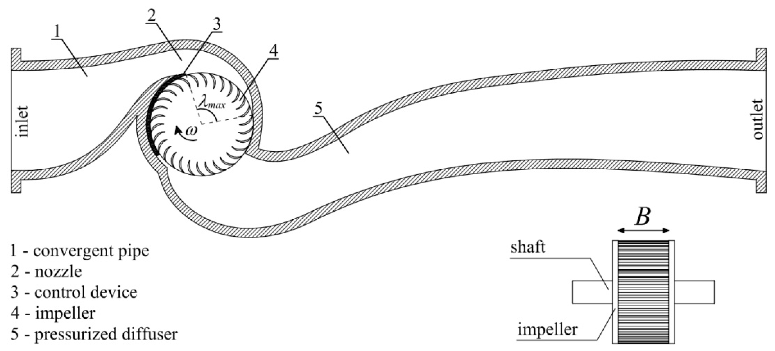
9]. The main advantage of the PRS, with respect to the other types of turbines, is that it has the capacity for hydraulic regulation by means of a mobile flap that can change the characteristic curve of the turbine, while still maintaining good efficiencies within a large range of head jumps and flow rates (see in
Figure 1 a section of the PRS normal to the turbine axis). Design criteria for the impeller diameter and the width B can be found in [
7,
8,
9].
In the design of Crossflow-type turbines, major attention is given to the maximization of hydraulic efficiency [
10]; on the other hand, mechanic failure of the turbine impeller is quite common in practice, due to the heavy loads and to the reduction of the maximum admissible stress occurring in a very short time as a result of the high frequency of the impeller rotation (500–1000 rpm). For this reason, reliable machines made with traditional materials require significant thickness of the blades, which is not ably larger than the thicknesses often used in laboratory or numerical experiments.
In the following sections, it is first shown, using simplified 2D simulations and a constant curvature of both the internal and the external surface, that the maximum efficiency is obtained when the external surface of the blade is tangent to the external circle of the impeller, but the corresponding maximum thickness may not be sufficient to guarantee mechanical safety. To maintain the same condition with a higher maximum thickness, it is necessary to move from a quadratic to a cubic shape of the external surface.
In the proposed design procedure, the external impeller radius, its width, and its rotational velocity are computed using the methodology already proposed in [
5]. The maximum thickness of the blades, their shape, the number of blades, and the possible allocation of an intermediate septum along the blade width are selected using an iterative procedure. The procedure starts from computation of the blade shape corresponding to a given maximum thickness, using a cubic function and the following conditions: a small initial and final thickness, measured along the radial direction of the internal surface with a circular profile, the maximum thickness value, and its derivative value at the external end according to the previously cited tangent optimality condition. The maximum pressure field acting on the surface of a single blade is then computed by solving a simplified 2D computational fluid dynamic (CFD) problem: using the computed pressure field, a finite element method (FEM) structural analysis, where the 3D effect of the blade constraints is accounted for, is solved for a single blade. After the iterative procedure attains stresses below the maximum allowed values, a fully 3D CFD simulation is run, along with a FEM structural analysis of the entire impeller.
2. Blade Design
The internal blade surface is simply designed as part of a cylinder, with the axis parallel to the impeller axis and its trace on the normal plane located at the intersection of the two directions orthogonal to the inlet and outlet relative velocities, as shown in
Figure 2 and Equations (1), where
V is the velocity norm,
D and
Di are the impeller outer and inner diameter, respectively,
α is the attack angle of the entering particles, and
ω is the rotational velocity of the impeller. The exit angle
β2 is set equal to 90°. The inlet angle
β1 is set in order to guarantee the tangent condition of the relative velocity at the intersection
P of the impeller outlet surface and the internal blade surface.
In
Table 1, see all the parameters of a PRS turbine, marked as PRS1, designed assuming a circular profile of the external surface, and in
Figure 3, for each possible φ value, the corresponding efficiency. The two ends of the circular profiles have been smoothed using a circular connection with a radius equal to 0.1 times the maximum thickness. We can observe in
Figure 3 that the maximum efficiency is attained for φ =
β1, corresponding to an external surface tangent to the impeller circle. The same optimality condition is also obtained in other tests (not documented here for brevity) using different design parameters for the turbine. The reason is likely to be the maximum reduction obtained for the actual
α attack angle of the entering particles, occurring along a large part of the inlet surface of each channel.
Let us call tmax,opt the maximum thickness corresponding to the tangent condition. Note that if this thickness is not sufficient for the blade’s structural resistance, since the maximum von Mises stresses are not lower than the admissible limits, the condition of maximum efficiency will be lost due to the need for a more robust design.
The previous results show how the simple criterion of the maximum efficiency can lead to poor mechanical design. To avoid that, we change the external surface moving from a second-order (circular) profile to the following third-order (cubic spline) profile:
where
t is the thickness measured along the radial direction of the internal surface and
δ is the angle between the radial direction and the direction orthogonal to the internal surface at the inlet point (
Figure 4a). Coefficients
a,
b,
c, and
d are computed by setting the following conditions:
where
tmax is the maximum thickness of the blade,
tmin is the thickness at the outer blade extremity,
t’ is the derivative with respect to
δ in the interval [
δmin;
θ],
tmin is set equal to 0.1
tmax, and
δ* is a fifth auxiliary unknown.
δmin and
t0 are computed by setting the tangent condition to the outer impeller surface and assuming a circular profile with radius
rf for the inner blade extremity, tangent in
P1 to the cubic spline profile of the external surface and in
P2 to the circular profile of the internal surface (
Figure 4b).
rf is set equal to 0.1
tmax.
Conditions 1–5 make it possible to maintain the tangent condition of the external surface to the outer impeller circumference for different possible values of the maximum thickness.
Figure 5 shows how the cubic profile makes it possible to maintain a much higher efficiency while changing the
tmax maximum thickness value.
3. Fluid Dynamic Investigation
Optimal impeller design could be achieved through a set of 3D CFD simulations and associated FEM analyses. However, this approach is computationally burdensome and would take many weeks or months of numerical calculation using standard computational resources. For example, a 3D CFD solution of a single configuration of the PRS1 turbine (
Table 1) required 15 days of transient simulation, using ANSYS
® CFX commercial code and parallel processing on several CPU Intel
® Xeon(R) E5-2650 v3 machines.
Due to the symmetry of the impeller with respect to a plane normal to its axis, the difference between the 2D and the 3D solution of a Banki turbine is usually small; this difference is even more negligible if the purpose of the simulation is to compare the efficiencies of two or more impeller geometries. Adopting the 2D assumption, the velocity and the pressure field of the same PRS1 turbine was obtained with a computational time of only 20 h.
Figure 6 shows the velocity field in the symmetry plane of the 3D simulation (left) and the same field obtained by 2D simulation (right). The results show good matching for the accuracy required by the iterative design problem.
4. Fluid Dynamic Investigation
The total power available at the turbine shaft is obtained by summing the torque of each individual blade multiplied by the rotational velocity of the impeller.
Let us define
τ as the ratio between the torque in the axis of the turbine provided by a single blade and the theoretical total torque, which is as follows:
In Crossflow impellers, the torque of the blades is not the same at a given time because it depends on the position of the blade itself.
Let us call τmax the maximum occurring t value. Using several CFD 2D test cases, not documented here for brevity, the behavior of this parameter was analyzed as a function of the number of blades of the impeller, within the range of 22–35 suggested by most of the authors. The results obtained for two different impellers provide a τmax value of about 0.12, which slowly decreases with an increasing number of blades.
5. Optimal Impeller Design
The optimal CFD and structural impeller design can be obtained by the following iterative procedure:
Choose the minimum reliable value for the maximum blade thickness tmax as the initial tentative value.
Compute the blade profiles according to the procedure explained in the previous section.
Solve a first CFD 2D model using an impeller with 35 blades (upper limit of the usual range) and export the pressure distribution on the blade surface.
Create a computer aided design (CAD) model of a single blade, based on the impeller width B and on the previously computed cross-section. Add to the CAD model a small portion of the two disks at the ends of the blade and apply the fillet radius at the blade–disk connection. If the turbine design includes one or more intermediate baffles, a fillet radius will be introduced on the connection baffle too. Use the pressure field on the blade previously computed in point 6.
Using an FEM code, compute the stress field and the maximum von Mises stress S.
If the maximum thickness used in point 4 does not make it possible to keep the maximum von Mises stress value below a predetermined admissible value, here indicated as Sadm, then a new attempt must be made either with a larger value of the maximum thickness or the introduction of a new reinforcing baffle. Using one or both of the new geometries, compute again the corresponding section and update the number of blades with the optimal one corresponding to the new maximum thickness by iteratively solving a CFD 2D model for each possible number. Update the pressure distribution on the blade surface and go back to point 5. The trial and error procedure must be repeated until the stress level is satisfactory.
Perform a final validation of the impeller geometry using only one CFD 3D simulation coupled with FEM analysis.
6. A Case Study: Fontes Episcopi Power Plant
We applied the proposed impeller design in a PRS turbine already installed in a pressure regulation node, named Fontes Episcopi, which is part of a larger water transport network of Sicily (Italy), named Gela-Aragona. The installed PRS turbine was designed with the following input parameters: Δ
H = 100 m,
Q = 100 L/s, and
ω = 1500 rpm, and its performances were reported in a previous work by some of the present authors [
8]. Using the same design parameters, a new PRS turbine, called the PRS2 turbine, was designed with the proposed procedure. Assuming
λmax= 110°, the impeller diameter
D and the width
B were found to be to 234 mm and 55 mm, respectively, by using the design methodology described in [
7,
8,
9].
Three different impellers, made of stainless steel, were designed using old blade geometry (impeller 1 and 2) and the new proposed blade geometry (impeller 3). The tensile strength for stainless steel, Sr, was set around 500 MPa, with a corresponding fatigue limit Sl equal to 250 MPa. The application of a reasonable safety factor provided Sadm =250/3 MPa = 83.3 MPa. The external surface of the blades of impeller 1 had a circular profile. The maximum efficiency was attained for φ = β1, corresponding to tmax= 5.12 mm and with a number of blades equal to 34. The value of the efficiency was η = 79.3%, computed by CFD 3D transient analysis. The maximum von Mises stress Smax = 117.76 MPa was not lower than the admissible limit (Sadm).
If the condition φ=β1 is relaxed, it is possible in impeller 2 to increase tmax up to 7 mm for the external circular profile, corresponding to an optimal number of blades equal to 27 (computed by CFD 2D analyses, and not reported here for brevity). In this case, the maximum von Mises stress is less than Sadm, but the efficiency decreases up to η = 78.2%.
The external surface of the blades of impeller 3 had a cubic profile, as computed according to the procedure described in
Section 5, with φ =
β1,
tmax = 7 mm, and
nb = 27. The resulting efficiency value was
η = 79.2%, and the maximum von Mises stress was lower than the admissible limit (
Sadm).
The von Mises stress of a single blade obtained by FEM analysis (
Figure 7) was similar to the final one computed with a CFD 3D simulation coupled with a FEM analysis and equal to 45.91 MPa.
In
Figure 8, the internal and external surfaces of the most loaded blade with the pressures computed by the final CFD 3D analysis are shown. The hypothesis of assuming constant pressures along the width for the most stressed blade is approximately validated.
Table 2 presents a summary of the results. The PRS with the proposed new impeller 3 had the best efficiency, and the corresponding maximum von Mises stress was below the admissible limit.
7. Conclusions
A new design criterion for Crossflow-type turbines, coupling hydraulic efficiency with mechanical reliability, was proposed and tested in a real case study. The proper use of 2D-CFD models and 3D-FEM structural models makes it possible to limit the computational effort in order to achieve the final design within a reasonable amount of time (a few weeks) via a standard work station with a few dozen processors.
The new methodology is also based on the non-circular profile of the external surface of the blades. Because Crossflow turbines are often selected for their constructive simplicity, this particular shape seems to be in conflict with the previous motivation. On the other hand, the size of Crossflow impellers remains quite small within significant power levels. Growing 3D printing technologies allow inexpensive construction of molds with very complex geometries but limited size, where mechanical components like the whole impeller can easily be obtained by fusion. The cost of the impeller, made with this new technology, turn out to be much smaller than the cost required using standard technologies for blades with a circular profile.

 ,
, 


