Abstract
This study investigates the effect on the flow structure in a backward-facing step (BFSF) due to a cylinder placed downstream of the step. Numerical simulations were carried out using OpenFOAM with several turbulence models (standard k-ɛ, RNG k-ɛ, standard k-ω, and SST k-ω). The recirculating flow, the skin friction coefficient (Cf), and the pressure coefficient (Cp) of the bottom wall were comparatively analysed. The added cylinder modified the structure of flow and increased the skin friction coefficient (Cf) in the recirculation zone. Additionally, the pressure coefficient of the bottom wall increased immediately downstream of the cylinder and farther downstream of the reattachment point remained stable in the flow recovery process.
1. Introduction
The backward-facing step flow (BFSF) is an important benchmark in fluid mechanics such as flow over stepped channels and large cavities. Flow structure in the BFSF involves several different flow regions: initial boundary layer, separated free shear layer, corner eddy, recirculation zone at the bottom wall, and redeveloping boundary layer (Figure 1).
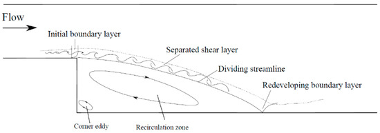
Figure 1.
Sketch of the turbulent flow field in a classical backward-facing step.
Due to the wide-ranging engineering applications, the study of backward-facing step flow has been conducted by many researchers. In particular, Armaly et al. [1] investigated the effect of Reynolds number on flow with separation by measurements of velocity distributions and the reattachment length over a wide Reynolds number range. According to Armaly et al. [1], the turbulent regime in the BFSF occurs for step-height Reynolds number Reh > 4950. Studies have already investigated the classical BFSF in turbulent flow, using experiments [1,2,3,4,5,6,7] as well as numerical studies [8,9,10,11,12,13] with different Reynolds numbers and expansion ratios. Those studies demonstrated that the reattachment length is independent of the step-height Reynolds number and increases with increasing expansion ratio. In addition, the BFSF with geometric modifications have been studied in recent years, such as the wavy bottom design downstream of the step by Uruba et al. [14] and the BFSF with an inclined step [15,16,17]. The results showed that the size of the recirculation zone increases with increasing step angle. When focusing on the skin friction coefficient (Cf), it was observed that it is strongly dependent on step-height Reynolds number [18]. Another well-known benchmark in fluids mechanics is the flow past a cylinder, which has been extensively studied for several decades. A cylinder is an example of a bluff body [19]. The presence of the cylinder downstream of the step changes the flow behavior from its behaviour in a classical BFSF. Some studies have been conducted to investigate the effect of a rotating cylinder on the BFSF of laminar flow and heat transfer [20,21,22,23]. The results demonstrated that by adding the rotating cylinder the convective heat transfer would be enhanced as a result of flow discontinuity.
Several studies have been implemented in relation to this geometry, however, most of the available literature is concerned with the heat transfer in laminar flow. In contrast, much less attention has been devoted to the effect of a stationary cylinder on the BFS flow in a turbulent regime. The present study focused on the two-dimensional numerical simulation of a turbulent flow in that geometry. The effect of the cylinder on the recirculation zone, the skin friction coefficient (Cf), and the pressure coefficient (Cp) at the bottom wall was investigated. Several turbulence models were comparatively applied using the Open-Source Field Operation and Manipulation (OpenFOAM) software package.
2. Materials and Methods
The turbulent flow was modeled using the Reynolds-Averaged Navier-Stokes (RANS) equations. Continuity and momentum equations for the two-dimensional flow of an incompressible fluid are given by:
Continuity equation:
Momentum equation:
where u and v = velocity components along the directions x and y; g = acceleration of gravity; p = pressure; ν = kinematic viscosity; and νt = turbulent eddy kinematic viscosity.
The standard k-ɛ is the most widely applied model in turbulence modeling. Its formulation is presented in Equations (4)–(6).
where ui,j = velocity components; ρ = fluid density; k = turbulent kinetic energy; ɛ = turbulent kinetic energy dissipation rate, whereas C1, C2, Cµ, σk, and σɛ are constants, and their values are listed in Table 1.

Table 1.
Values of the constants of the standard k-ε model.
The initial values of turbulent kinetic energy and dissipation rate can be estimated by:
where ureff = inlet flow velocity; l = 0.07L (L = characteristic inlet scale (m)); Ti = turbulent intensity (5%). In omega-based models, ω is the specific dissipation rate, of which the initial value can be estimated:
Two geometries, classical backward-facing step (BFSF 1) and backward-facing step with a cylinder (BFSF 2), were considered. The geometries and computational mesh were created using the blockMesh utility. The design of the BFSF 1 was based on the experimental model of Armaly et al. [1]. The expansion ratio (ER = h2/h1) was 2, which was very close to that of Armaly et al. [1] (ER = 1.94). In the BFSF 2, a cylinder with a diameter D = 4.5 mm was added at a 4.5 mm distance in the x-direction from the step edge. As shown in Figure 2, the top half of the cylinder was located above the top surface (mid-plane) of the step. The BFSF 2 is presented in Figure 2.
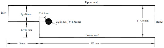
Figure 2.
Sketch of the backward-facing step geometry with a cylinder (BFSF 2).
The standard k-ɛ, RNG k-ɛ, standard k-ω, and SST k-ω turbulence models were comparatively used. The following boundary and initial conditions were applied.
- Inlet: fixedValue for velocity and turbulence fields (k, ɛ, and ω), zero gradient for pressure.
- Outlet: fixedValue for pressure, inletOutlet for velocity, and zero gradient for turbulence fields.
- Walls (upper and bottom wall, cylinder): zero gradient for pressure, no-slip for velocity, and near-wall conditions for turbulence fields (i.e., kqRWallFunction, epsilonWallFunction, and omegaWallFunction).
- Initial values for pressure (p = 0) and velocity (u = 0.801 m/s) were used. Additionally, the initial values of turbulence quantities were calculated using Equations (7)–(9): k = 0.002406 m2/s2, ɛ = 0.0277 m2/s3, ω = 124.82 1/s.
- The Reynolds number based on the step height (h) was 9000.
- The Reynolds number based on the cylinder diameter (D) was = 2015.
Structured meshing is generally more straightforward to implement, faster to execute, and tends to be more accurate than unstructured ones [24]. In this study, the structured rectangular hexahedral mesh was considered. In addition, mesh independence was assessed using experimental data [1]. To do so, the BFSF 1 was tested in four meshes with different cell sizes. It is worth mentioning that the cell size in the vicinity of the wall and cylinder was fine to have enough resolution. The details of the meshes used in both geometries are listed in Figure 3.
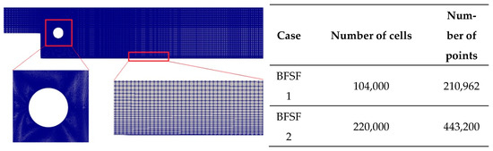
Figure 3.
Schematic of the mesh used and number of mesh elements.
3. Results and Discussion
3.1. Recirculation Zone and Cylinder Wake
As shown in Figure 4a, in the BFSF 1, the flow separated at the sharp corner of the step and reattached downstream at the bottom wall. The reattachment length Lr1 in the BFSF 1 from several turbulence models was compared with literature experimental data and numerical results. Table 2 lists the value of the reattachment lengths in the BFSF 1 and BFSF 2.
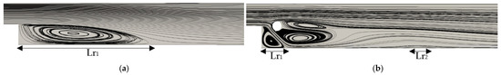
Figure 4.
Streamlines of the flow at Rec = 2015 (Reh = 9000), (a) BFSF 1, (b) BFSF 2.
Table 2.
Reattachment length in past numerical and experimental works.
In the BFSF 1, the reattachment length is mostly between 5 and 8 times the step height which was in agreement with the present study. If compared with experimental data [7] and numerical results at Reh = 9000 and ER = 2 [7,10], the most accurate model in predicting Lr1 was the standard k-ɛ. The average error between this study and experimental [7] and two-dimensional numerical results [7,10] was lower than 3% and 6%, respectively.
In the BFSF 2, the flow separated at the step and reattached to the bottom wall. A second recirculation zone (Lr2) was observed far away from the primary recirculation zone at the bottom wall. Armaly et al. [1] reported that a second recirculation zone was not found in their study for Reh > 1725. However, in this study, the cylinder modified the flow over the backward-facing step and a second recirculation zone was observed even for Reh = 9000. The size of the Lr2 was smaller than that of the Lr1. Figure 4 shows flow patterns of the BFSF 1 and BFSF 2 in the turbulent flow.
The structure of the flow past a cylinder in a rectangular channel depends on the Reynolds number. For the range of Reynolds number 1000 < Rec < 2 × 10⁵, the flow behind a cylinder develops and the boundary layers separate from the front stagnation point. There is a fully developed turbulent wake downstream of the cylinder [28,29]. In this study, when a cylinder was placed downstream of the step (BFSF 2) at Rec = 2015, the step affected the near wakes of the cylinder by changing the dynamics of the vortex generation, and two vortices formed behind the cylinder in different sizes. However, in this range of Reynolds number in flow past a cylinder, the vortex shedding process becomes fully turbulent in the wake, and vortex street forms. As shown in Figure 4b, two recirculation bubbles were observed downstream of the cylinder, with the size of the lower wake recirculation bubble being larger than that of the upper one.
3.2. Skin Friction Distributions
The skin friction coefficient, Cf, is a dimensionless quantity derived from the wall shear stress (τw) as:
The distribution of skin friction coefficient (Cf) at the bottom wall was calculated. As shown in Figure 5, the skin friction coefficient of the BFSF 1 and BFSF 2 for different turbulence models were compared with literature results. Note that in the BFSF 2, the locations were scaled using Lr1 from the standard k-ɛ model in the BFSF 1, rather than that in the BFSF 2. In Figure 5, the dotted line shows the position of the cylinder center.
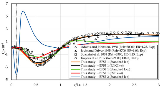
Figure 5.
The longitudinal distribution of Cf at the bottom wall downstream of the step.
In the BFSF 1, the Cf decreased and reached the minimum peaks in the recirculation zone and gradually recovered to positive values after the reattachment point. The constant value skin friction coefficient downstream showed fully developed channel flow. Table 3 lists the values of the minimum peaks of Cf, and its location in the BFSF 1 and BFSF 2.
Table 3.
Skin friction coefficient and its position in past numerical and experimental works.
In the BFSF 1, the distribution of skin friction in the standard k-ɛ and RNG k-ɛ turbulence models showed almost the same distributions of skin friction as the literature experimental data [2,25] and numerical results [11]. The results were compared with the available numerical results [11] at Reh = 9000 and ER = 2. The average error was lower than 17.5% for the BFSF 1. The most accurate model in predicting skin friction coefficient was the standard k-ɛ, followed by RNG k-ɛ, standard k-ω, and SST k-ω. Considering the accuracy and the calculation time of the models, only the standard k-ɛ model was used for the BFSF 2.
As previously pointed out, two recirculation zones (Lr1 and Lr2) were observed in the BFSF 2. The negative peak of the skin friction coefficient (Cf, min) occurred due to the recirculating flow where the velocity distribution changed. In the BFSF 2, two peaks of Cf, min were observed. In the BFSF 2, the value of (Cf, min)1 increased while its position was found to be upstream compared to the BFSF 1. The second negative peak (Cf, min)2 was observed far away from the primary one at the bottom wall and its value was smaller than that of the primary (Cf, min)1.
3.3. Static Pressure Coefficient
One of the most important characteristics of the bottom wall is the pressure coefficient. The wall static pressure coefficient is defined as:
where P is the wall static pressure in any location and P0 is the reference wall static pressure measured at x = −4h, y = 1.5h (h is step height) upstream of the step as suggested by Kopera et al. [11]. The distribution of pressure in the standard k-ɛ for the BFSF 1 and BFSF 2 is shown in Figure 6.
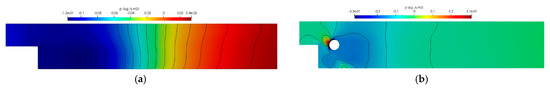
Figure 6.
Distribution of pressure in the standard k-ɛ model, (a) BFSF 1, (b) BFSF 2.
In the BFSF 1, the static pressure increased starting from the corner of the bottom wall. In the BFSF 2, a sharp increase in pressure occurred in front of the cylinder, however, the pressure behind the cylinder decreased. According to Kim et al. [31], to normalize the variations due to the different expansion ratios of the BFSF, the normalized pressure coefficient (C*p) was defined as:
where Cp,min is the minimum pressure coefficient and ) is the Borda–Carnot pressure coefficient [31]. The normalized pressure coefficients (C*p) against the location scaled with the reattachment position are compared in Figure 7.
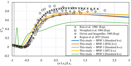
Figure 7.
The longitudinal distribution of pressure coefficient of bottom wall downstream of the step.
In the BFSF 1, a sharp increase in pressure occurred in the reattachment zone (from x = 3 h to x = 7 h), consistent with the literature results [11,31,32,33]. The distribution of pressure farther downstream remained relatively stable in the flow recovery process. The Cp values computed by the different turbulence models at the bottom wall ranged from −0.143 to 0.35 and their distribution agreed with literature experimental data [31,32,33] and numerical results [11]. In the BFSF 2, the minimum and maximum values of the pressure coefficients were lower than those in the BFSF 1. The Cp values ranged from −0.39 to 0.115 on the bottom wall in the BFSF 2. The cylinder affected the distribution of pressure along the bottom wall. In the BFSF 2, the variation of the pressure downstream of the cylinder at the bottom wall could have two causes: the streamline curvature and the high turbulence intensity. The average value of Cp downstream of the reattachment point was smaller than that in the BFSF 2 if compared to the BFSF 1.
4. Conclusions
In the present study, turbulent flow over the classical BFSF (BFSF 1) and BFSF with a cylinder placed downstream of the step (BFSF 2) was investigated.
In the BFSF 2, the cylinder pushed the primary recirculation region upstream to the corner of the step and its length was shorter than for the BFSF 1. In the BFSF 2, the second recirculation zone was observed far away from the primary recirculation zone on the bottom wall and its length was shorter than that of the primary recirculation zone. The step modified the structure of the flow past of the cylinder, leading to an asymmetric wake distribution. Two vortices formed behind the cylinder in different sizes and their location was shifted towards the bottom wall.
In the BFSF 1, a negative value of skin friction coefficient (Cf,min) at the bottom occurred due to the recirculating flow. However, in the BFSF 2, two peaks of negative (Cf, min)1 and (Cf, min)2 were observed due to the two recirculation zones. The value of primary (Cf, min)1 was higher than that in the BFSF 1. In the BFSF 1, the pressure coefficient at the bottom wall peaked around the reattachment point and farther downstream remained relatively stable in the flow recovery. In the BFSF 2, the pressure coefficient at the bottom wall increased immediately downstream of the cylinder. In the BFSF 2, the average value of Cp downstream of the reattachment point was smaller than that in the BFSF 1.
Author Contributions
This paper is done under the joint effort of all authors. Conceptualization, C.G.; Methodology, M.A. and C.G.; Software, Validation, Formal Analysis and Investigation, M.A.; Data Curation M.A. and C.G.; Writing—Original Draft Preparation, M.A.; Writing—Review & Editing, C.G. and P.G.; Visualization M.A.; Supervision, C.G. and P.G. All authors discussed the results and contributed to the final manuscript. All authors have read and agreed to the published version of the manuscript.
Funding
This research received no external funding.
Data Availability Statement
The datasets generated during and/or analyzed during the current study are available from the corresponding author on reasonable request.
Conflicts of Interest
The authors declare no conflict of interest.
References
- Armaly, B.F.; Durst, F.; Pereira, J.; Schönung, B. Experimental and theoretical investigation of backward-facing step flow. J. Fluid Mech. 1983, 127, 473–496. [Google Scholar] [CrossRef]
- Jovic, S.; Driver, D. Reynolds number effect on the skin friction in separated flows behind a backward-facing step. Exp. Fluids 1995, 18, 464–467. [Google Scholar] [CrossRef]
- Furuichi, N.; Hachiga, T.; Kumada, M. An experimental investigation of a large-scale structure of a two-dimensional backward-facing step by using advanced multi-point LDV. Exp. Fluids 2004, 36, 274–281. [Google Scholar] [CrossRef]
- Tihon, J.; Pěnkavová, V.; Havlica, J.; Šimčík, M. The transitional backward-facing step flow in a water channel with variable expansion geometry. Exp. Therm. Fluid Sci. 2012, 40, 112–125. [Google Scholar] [CrossRef]
- Costantini, M.; Risius, S.; Klein, C. Experimental investigation of the effect of forward-facing steps on boundary layer transition. Procedia IUTAM 2015, 14, 152–162. [Google Scholar] [CrossRef]
- Terekhov, V.; Smul’skii, Y.I.; Sharov, K. Experimental study of the separated flow structure behind a backward-facing step and a passive disturbance. J. Appl. Mech. Tech. Phys. 2016, 57, 180–187. [Google Scholar] [CrossRef]
- Wang, F.-F.; Wu, S.-Q.; Zhu, S.-L. Numerical simulation of flow separation over a backward-facing step with high Reynolds number. Water Sci. Eng. 2019, 12, 145–154. [Google Scholar] [CrossRef]
- Iaccarino, G. Predictions of a turbulent separated flow using commercial CFD codes. J. Fluids Eng. 2001, 123, 819–828. [Google Scholar] [CrossRef]
- Kim, D.; Moin, P. Direct Numerical Study of Air Layer Drag Reduction Phenomenon Over a Backward-Facing Step. In Center for Turbulence Research Annual Research Briefs 2010, Proceeding of the 63rd Annual Meeting of the APS Division of Fluid Dynamics, Long Beach, CA, USA, 21–23 November 2010; Center for Turbulence Research: Stanford, CA, USA, 2010; pp. 351–362. [Google Scholar]
- Araujo, P.P.; Rezende, A.L.T. Comparison of turbulence models in the flow over a backward-facing step. Int. J. Eng. Res. Sci. 2017, 3, 88–93. [Google Scholar] [CrossRef]
- Kopera, M.A.; Kerr, R.M.; Blackburn, H.; Barkley, D. Simulation of turbulent flow over a backward-facing step at Re= 9000. Phys. Fluids 2017. in review. [Google Scholar]
- Luo, D. Numerical simulation of turbulent flow over a backward facing step using partially averaged Navier-Stokes method. J. Mech. Sci. Technol. 2019, 33, 2137–2148. [Google Scholar] [CrossRef]
- Yang, D.; He, S.; Shen, L.; Luo, X. Large eddy simulation coupled with immersed boundary method for turbulent flows over a backward facing step. Proc. Inst. Mech. Eng. Part C J. Mech. Eng. Sci. 2021, 235, 2705–2714. [Google Scholar] [CrossRef]
- Uruba, V.; Jonáš, P.; Mazur, O. Control of a channel-flow behind a backward-facing step by suction/blowing. Int. J. Heat Fluid Flow 2007, 28, 665–672. [Google Scholar] [CrossRef]
- Prihoda, J.; Zubik, P.; Sulc, J.; Sedlar, M. Experimental and numerical modelling of turbulent flow over an inclined backward-facing step in an open channel. Commun.-Sci. Lett. Univ. Zilina 2012, 14, 6–12. [Google Scholar] [CrossRef]
- Louda, P.; Příhoda, J.; Kozel, K.; Sváček, P. Numerical simulation of flows over 2D and 3D backward-facing inclined steps. Int. J. Heat Fluid Flow 2013, 43, 268–276. [Google Scholar] [CrossRef]
- Choi, H.H.; Nguyen, J. Numerical investigation of backward facing step flow over various step angles. Procedia Eng. 2016, 154, 420–425. [Google Scholar] [CrossRef]
- Tihon, J.; Legrand, J.; Legentilhomme, P. Near-wall investigation of backward-facing step flows. Exp. Fluids 2001, 31, 484–493. [Google Scholar] [CrossRef]
- Modarres-Sadeghi, Y. Introduction to Fluid-Structure Interactions; Springer Nature: Berlin/Heidelberg, Germany, 2022. [Google Scholar]
- Selimefendigil, F.; Öztop, H.F. Numerical investigation and reduced order model of mixed convection at a backward facing step with a rotating cylinder subjected to nanofluid. Comput. Fluids 2015, 109, 27–37. [Google Scholar] [CrossRef]
- Hussain, S.; Ahmed, S.E. Unsteady MHD forced convection over a backward facing step including a rotating cylinder utilizing Fe3O4-water ferrofluid. J. Magn. Magn. Mater. 2019, 484, 356–366. [Google Scholar] [CrossRef]
- Anguraj, A.; Palraj, J. Numerical study of fluid flow and heat transfer in a backward facing step with a rotating cylinder. Malaya J. Mat. (MJM) 2018, 6, 435–442. [Google Scholar] [CrossRef]
- Tahseen, T.A.; Eleiwi, M.A.; Hameed, A.F. Numerical study of fluid flow and heat transfer in a backward facing step with three adiabatic circular cylinder. J. Adv. Res. Fluid Mech. Therm. Sci. 2020, 72, 80–93. [Google Scholar]
- Biswas, R.; Strawn, R.C. Tetrahedral and hexahedral mesh adaptation for CFD problems. Appl. Numer. Math. 1998, 26, 135–151. [Google Scholar] [CrossRef]
- Spazzini, P.G.; Iuso, G.; Onorato, M.; Zurlo, N.; Di Cicca, G. Unsteady behavior of back-facing step flow. Exp. Fluids 2001, 30, 551–561. [Google Scholar] [CrossRef]
- Yao, S. Two Dimensional Backward Facing Single Step Flow Preceding an Automotive Air-Filter; Oklahoma State University: Stillwater, OK, USA, 2000. [Google Scholar]
- Barri, M.; El Khoury, G.K.; Andersson, H.I.; Pettersen, B. DNS of backward-facing step flow with fully turbulent inflow. Int. J. Numer. Methods Fluids 2010, 64, 777–792. [Google Scholar] [CrossRef]
- Panton, R.L. Incompressible Flow; John Wiley & Sons: Hoboken, NJ, USA, 2013. [Google Scholar]
- Southard, J. Introduction to Fluid Motions and Sediment Transport; Massachusetts Institute of Technology: Cambridge, MA, USA, 2019. [Google Scholar]
- Adams, E.; Johnston, J. Effects of the separating shear layer on the reattachment flow structure part 2: Reattachment length and wall shear stress. Exp. Fluids 1988, 6, 493–499. [Google Scholar] [CrossRef]
- Kim, J.; Kline, S.; Johnston, J.P. Investigation of a reattaching turbulent shear layer: Flow over a backward-facing step. J. Fluids Eng. 1980, 102, 302–308. [Google Scholar] [CrossRef]
- Westphal, R.V.; Johnston, J.; Eaton, J. Experimental Study of Flow Reattachment in a Single-Sided Sudden Expansion. 1984. Available online: https://ntrs.nasa.gov/citations/19840010503 (accessed on 4 September 2013).
- Driver, D.M.; Seegmiller, H.L. Features of a reattaching turbulent shear layer in divergent channelflow. AIAA J. 1985, 23, 163–171. [Google Scholar] [CrossRef]


Publisher’s Note: MDPI stays neutral with regard to jurisdictional claims in published maps and institutional affiliations. |
© 2022 by the authors. Licensee MDPI, Basel, Switzerland. This article is an open access article distributed under the terms and conditions of the Creative Commons Attribution (CC BY) license (https://creativecommons.org/licenses/by/4.0/).