Article

Carbon Dioxide Capture under Low-Pressure Low-Temperature Conditions Using Shaped Recycled Fly Ash Particles

Department of Petroleum and Energy Engineering, The American University in Cairo, New Cairo 11835, Egypt
*
Author to whom correspondence should be addressed.
Gases 2024, 4(2), 117-132; https://doi.org/10.3390/gases4020007
Submission received: 16 December 2023 / Revised: 26 March 2024 / Accepted: 18 April 2024 / Published: 23 May 2024

Abstract

:
Carbon-capture technologies are extremely abundant, yet they have not been applied extensively worldwide due to their high cost and technological complexities. This research studies the ability of polymerized fly ash to capture carbon dioxide (CO2) under low-pressure and low-temperature conditions via physical adsorption. The research also studies the ability to desorb CO2 due to the high demand for CO2 in different industries. The adsorption–desorption hysteresis was measured using infrared-sensor detection apparatus. The impact of the CO2 injection rate for adsorption, helium injection rate for desorption, temperature, and fly ash contact surface area on the adsorption–desorption hysteresis was investigated. The results showed that change in the CO2 injection rate had little impact on the variation in the adsorption capacity; for all CO2 rate experiments, the adsorption reached more than 90% of the total available adsorption sites. Increasing the temperature caused the polymerized fly ash to expand, thus increasing the available adsorption sites, thus increasing the overall adsorption volume. At low helium rates, desorption was extremely lengthy which resulted in a delayed hysteresis response. This is not favorable since it has a negative impact on the adsorption–desorption cyclic rate. Based on the results, the polymerized fly ash proved to have a high CO2 capture capability and thus can be applied for carbon-capture applications.

1. Introduction

CO2 storage is one of the most researched topics nowadays due to its ability to reduce greenhouse gas emissions and allow for the future use of CO2 if needed [1,2,3,4,5]. There are many methods by which CO2 can be stored, including reacting the CO2 with other substances, directly utilizing the CO2, and direct storage in underground reservoirs. The main parameter when designing the storage operation is the ability to re-access the stored CO2 for future utilization to abide by the carbon capture, utilization, and storage (CCUS) initiative [6]. When storing the CO2 in depleted underground reservoirs, the long-term stability of the CO2 is highly questionable. Therefore, stabilizing material can be used to force the CO2 to adsorb, or adhere, to the surface of that material. This can allow for a safer and longer storage potential thus increasing the viability of the overall storage process. The stabilizing material may also increase the CO2 storage capacity in the reservoir through chemical reactions [7,8,9].
For CO2 adsorption to take place, there must be a material that has an affinity to the CO2 and thus allows for the fluid to adhere to its surface. One of the most prominent materials that has been found to be able to adsorb CO2 is fly ash. Fly ash is a waste material that is produced as a byproduct of combustion [10,11,12,13,14,15]. When organic material burns, it produces waste residue. Part of this residue settles; this is referred to as bottom ash. The other part of the fly ash has a very low density and thus can be easily carried away; this is referred to as fly ash. Bottom ash contains many hazardous chemicals and thus is not as widely used as fly ash. Fly ash is classified based on its composition, which varies according to the source of the fly ash. It can contain traces of metals, along with other elements such as sulfur depending on its source [16,17,18,19,20]. Fly ash has been found by many researchers to have an affinity to CO2 and thus can be used as a stabilizing material for CO2 storage in depleted underground reservoirs.
Fly ash has been researched for carbon capture under different conditions. The main mechanism of CO2 adsorption to fly ash is physical adsorption. Physical adsorption occurs at very low energy levels; therefore, it is classified as weak adsorption. In physical adsorption, the adsorbate is held-on the adsorbent via Van Der Waals forces, which are the same forces that hold the water molecules together. Since physical adsorption is a weak adsorption, the ability for this adsorption to remain intact for a long duration is questionable. The main advantage of physical adsorption is that it is classified as multi-layer adsorption. Once the first layer of adsorbate is formed, a second later forms on top of the first layer, which is referred to as the stacking effect. The bond strength of each layer becomes weaker until there is not enough energy for a further layer to form. Different types of fly ash have been studied for CO2 capture. Yao [21] studied the use of coal fly ash for CO2 capture. Based on their results, this type of fly ash has a high affinity to CO2. This affinity is impacted by multiple factors including metal content, fly ash purity, and temperature and pressure conditions of adsorption. Prasad [22] focused on the impact of manganese concentration in coal fly ash and reached the same conclusion as the previously mentioned study. Kikuchi [23] investigated the conversion of fly ash to zeolites for CO2 capture and storage. Zeolites were found to have superior properties compared to the raw fly ash; however, a conversion step was needed. Also, under different conditions, the formed zeolite will have different properties and thus will result in a different adsorption potential. The main limitation of these studies is that each type of fly ash is different in composition and origin, which limits the ability to generalize the behavior of fly ash when used for CO2 capture or storage.
Different materials have been utilized for CO2 capture based on their properties and characteristics. Shafeean [24] investigated the increase in CO2 adsorption on the surface of activated carbon using gaseous ammonia to modify the surface structure of the activated carbon. Reddy [25] reviewed the properties of different material that are potential candidates for CO2 adsorption including clays, metal oxides, porous carbons, and zeolites. They did not include fly ash in their review. Baltrusaitis [26] studied the CO2 adsorption capacity on different metal oxide nanoparticles such as iron oxide and aluminum oxide. Chun [27] performed a review on the surface chemistry of different materials used for CO2 adsorption to determine the different methods available for the surface of these material to selectively adsorb CO2. Guo [28] studied the adsorption potential of CO2 on three different types of activated carbon at elevated temperature and pressure. Saha [29] presented adsorption isotherms for activated carbon at elevated pressures, reaching 10 MPa, and temperatures ranging from −18 to 80 °C. Bonenfant [30] showed that two of the significant parameters that impact CO2 adsorption to the surface of zeolites include pH and charge. Mishra [31] presented experimental work on the enhancement of nano graphene particles’ ability to adsorb CO2 through hydrogen exfoliation. Hinkov [32] studied the use of zeolites, molecular sieves, metal–organic frameworks, hydrotalcite-like compounds, and advanced adsorbent for CO2 capture. By impregnating this material with nitrogen-containing species, the CO2 capture potential increased significantly. Zhang [33] utilized deep-learning methods to predict the ability of CO2 to adsorb the surface of different material. Shafeeyan [34] developed a mathematical model to predict fixed-bed carbon dioxide adsorption to different materials. Li [35] investigated the utilization of metal-organic frameworks for CO2 capture through direct adsorption. Yong [36] conducted a review on different materials for CO2 adsorption including zeolites, activated carbon, and other materials. They did not test fly ash in their experiments. Hassanpouryouzband [37] researched an innovative method for flue gas and CO2 storage in the form of solid hydrates in oceans. This method relies on a natural phenomenon that occurs when water and a gas are subjected to low temperature and high pressure, both of which are features of oceans.
Many studies have investigated the use of fly ash in several applications due to its low cost and advantageous properties. Panchal, S., and Debasis, D. [38] investigated the use of fly ash as a cost-effective high-performance mine backfill material. Tosun, Y.I [39] studied the use of fly ash as a construction material by testing the different strengths of the material including tensile, compressive, and shear strength. Nyakilla, E. et al. [40] applied a modified modeling method to determine the characteristics of fly-ash-reinforced cement. The model is specific to the type of fly ash used since the fly ash varied significantly depending on the source of the fly ash and its precursor material. Krstic, M. et al. [41] researched the utilization of fly ash for soil stabilization especially for road construction. The focus of the research was on fine-grained soil. Adewunmi, A., and Kamal, M [42] performed one of the first studies on the application of fly ash as a demulsifying agent for stable water–oil emulsion caused by asphaltene. Adjei, S. et al. [43] highlighted the need for the utilization of novel material to prolong the setting time of the cement in deep wells. The study mentioned that fly ash can be used as an effective extender material for cement in oil and gas wells. Cella, P., and Taylor. S [44] developed a method to determine corrosion in different materials including cement mortars. Different mortar samples were prepared using conventional cement and fly ash with different concentrations. The electrical method was then applied to determine the corrosion potential of different chemicals on the cement mortar samples. Montemor, M. et al. [45] investigated the use of a thin film fly ash cement protection on the surface of steel to prevent corrosion in the presence of chlorine ions and CO2. The fly managed to inhibit the degradation of the steel under both conditions. Cunningham, W. et al. [46] developed a novel cement referred to as “permafrost” cement using a mixture of cementing material including fly ash. The cement could be used effectively under extremely low temperature conditions.
Based on the aforementioned, many factors can impact the CO2 storage capacity in depleted underground reservoirs when using fly ash. It is therefore important to test different fly ash samples to determine the applicability of fly ash with different compositions in the long-term underground storage of CO2. This research studies the ability of a high-metal-content fly ash obtained from a cement manufacturer to aid in the storage of CO2 in depleted underground reservoirs and investigates some of the main factors that can impact the storage potential such as temperature, fly ash surface area, and gas injection rates. By evaluating these factors, the main parameters impacting the ability of fly ash to capture CO2 can be identified. Also, the impact of each of these parameters is quantified. This can help in the improvement of scalable projects using fly ash by optimizing the large-scale model and by optimizing the selection of the proper location to apply the technology.

2. CO2 Storage Methods

One of the most important components of the CCUS initiative is the ability to store the captured CO2. There are many methods by which this can be achieved. These include storage in underground depleted reservoirs, most notably depleted hydrocarbon reservoirs, storage in CO2 sinks such as forests and oceans (most notably in the form of hydrates), storage in cementing material such as CO2 integrated cement, and storage through conversion into other material such as calcium carbonate [36].
Many factors will impact the selection of the storage method. These depend on the method itself and the properties of the captured CO2. These factors include the following:
CO2 Quality: The quality of the gas will affect its overall properties including flow behavior, reactivity with other fluids and with solids such as rocks and cement, compressibility and phase behavior, and environmental impact. An example of this is flue gas which includes CO2 along with other gases, some of which can be environmentally damaging such as hydrogen sulfide and carbon monoxide. Depending on the quality of the CO2, different methods of storage should be eliminated.
CO2 Phase and Availability: The CO2 phase is a strong function of pressure and temperature. Normally, the CO2 will either be in liquid or gaseous phase until the pressure exceeds 1071 psi and 31 °C at which the phase will become supercritical. The phase is important since it impacts the properties of the CO2 including density, viscosity, and flow behavior. The availability of CO2 depends on the location of storage and the available CO2 capture technology.
Method Selectivity: Although many CO2 storage methods are available, each method has advantages and limitations. This depends on the mechanism of each method, interactions and materials, and technological requirements in the target implementation location.
Safety and Environment: The main criteria for CO2 storage applications methods are safety and environmental impact. Although many methods have been proposed, several of these methods lack long-term stability. This includes storage in underground reservoirs, or in other materials such as cement. It is imperative that the long-term stability of CO2 be tested before implementation of the storage method to avoid leakages over time.
Economic Feasibility: One of the drawbacks of many CO2 storage methods is the overall cost of application. This can cause several institutions to avoid venturing into CO2 storage operations. It is important to test the economic feasibility of the CO2 storage method before implementation.

3. Experimental Description

The material, setup, and procedure used to conduct all the experiments is presented in this section.

3.1. Experimental Material

The material was selected based on availability and cost. This was to ensure that a continuous supply could be obtained when needed. Also, the low cost of the material is imperative for the scalability of the project since reduction in cost is one of the key advantages using fly ash for CO2 capture compared to other methods. The material used to conduct the experiment in this study are as follows:
  • CO2: The CO2 was provided in a pressurized cylinder with an initial pressure of 1200 psi. The cylinder was connected to a pressure regulator.
  • Helium: The helium was provided in a pressurized cylinder with an initial pressure of 2400 psi. The cylinder was connected to a pressure regulator and connected to the setup via high-pressure tubing.
  • Fly Ash: The fly ash used was purchased from a cement factory as a light-grey power with small traces of metals and impurities.
  • Heat Jacket: The heat jack was internally imbedded within the adsorption vessel with a maximum temperature of 70 °C.
  • Pressure Transducers: The pressure transducers were allocated across the setup for pressure reading and logging.

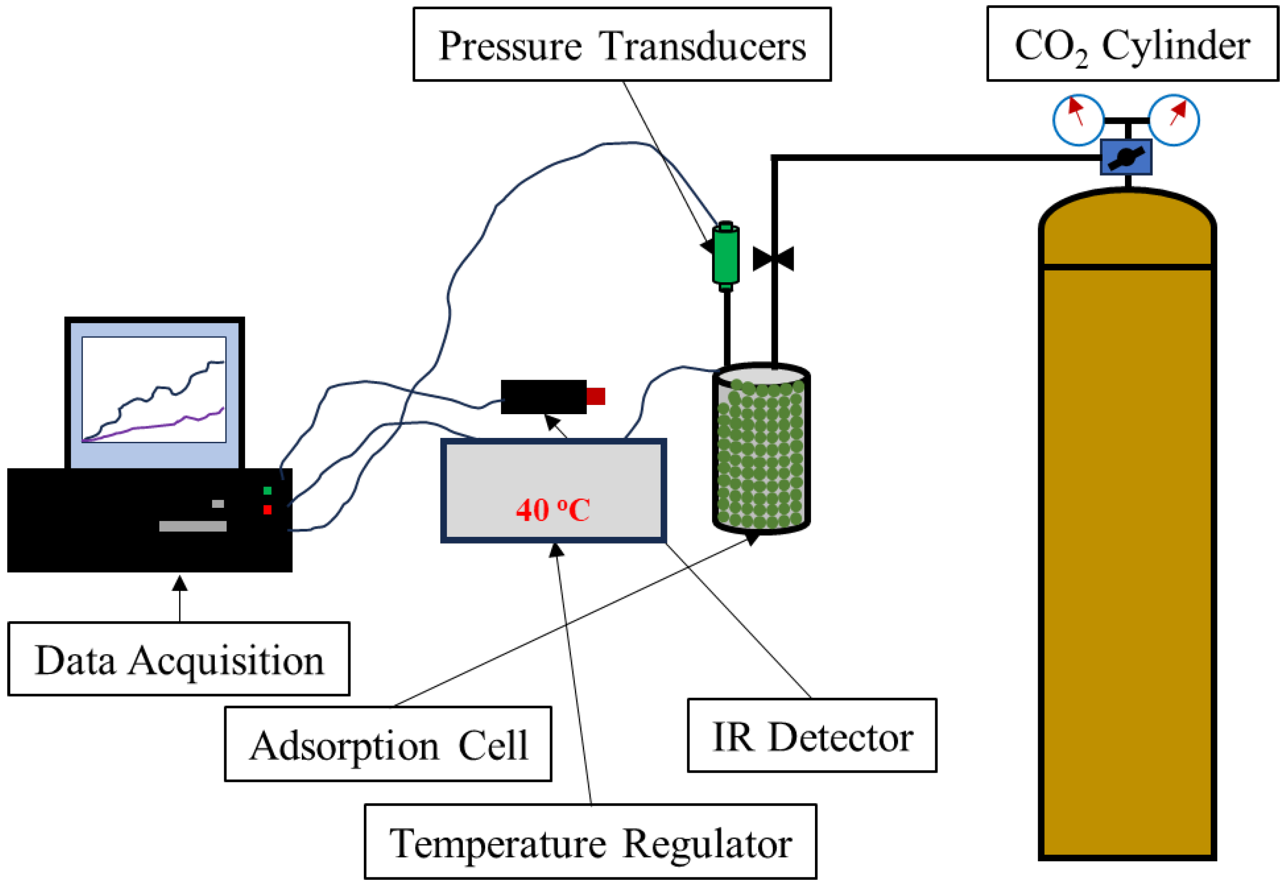
3.2. Experimental Setup

The setup used to conduct all experiments is shown in Figure 1. The setup is composed of an adsorption cell which houses the fly ash. CO2 and helium cylinders provide a continuous source of the gasses for the adsorption and desorption cycles, respectively. A temperature regulator is attached to the setup panel controller which is also connected to a computer for data acquisition and logging.

3.3. Experimental Procedure

The procedure followed to conduct all the experiments in this research are as follows:
  • The adsorption cell was disconnected from the setup and filled with fly ash. It was important to ensure that the cell was well packed to avoid disturbance of the infrared readings during the experiment. Packing of the cell was conducted in a manner that would also leave space for the temperature thermocouples in order to record the temperature at different locations in the cell.
  • The cell was then sealed and reconnected to the setup. Sealing of the cell was performed using metal bolts and a rubber seal to avoid leakage during the experiments. The valves were maintained closed until the experiment was ready.
  • For experiments conducted at temperatures above room temperature (25 °C), the temperature regulator was adjusted to the design temperature and left for 12 h, or overnight, to ensure that the temperature was constant across the setup. The temperature was monitored using four thermocouples allocated across the setup.
  • The CO2 was then injected into the setup at a design flowrate and the experiment began. Once the adsorption percentage stabilized, desorption occurred using helium. CO2 and helium were connected to the setup via high-pressure tubing, each with its own pathway to avoid gas crossflow.
  • The experiment was concluded when the CO2 adsorption percentage reached zero. The adsorption cell was completely evacuated and then disconnected and opened to replace the fly ash sample.

3.4. Fly Ash Cube Synthesis

The fly ash powder used to run all the experiments was shaped into uniform cubes with a surface area of 18.2 cm2. In order to shape the fly ash into a solid cube, an alkaline activator is usually used. In most cases, a mixed solution of sodium hydroxide and sodium silicate is used. In this research, the alkaline activator used was sodium metasilicate. This is a single binder with the properties of the sodium hydroxide/sodium silicate mixture. Water was used as the solution for the sodium metasilicate. The fly ash was mixed with the alkaline activator solution using an electric blender. The solution was then placed in the cubic molds and was left to solidify overnight. The cubes were then extracted from the molds. Any cubes with non-uniform edges or broken sections were rejected. A total of 20 cubes were used in the setup with the total contact surface area for CO2 being 364 cm2.

4. Results and Analysis

Figure 2 shows a general plot that will be used to show the results for all the experiments. The same colors and axis will be used to explain all the results. The green data points indicate the adsorption phase of the experiment. The adsorption is measured via the infrared sensor which records it as a percentage. The percentage indicates the volume of CO2 adsorbed on all available sites for adsorption in the experimental setup. Once adsorption reaches a stable value, desorption will be conducted; this is represented by the orange data points. The desorption is also detected via the infrared sensor and is represented as a percentage. The volume of adsorbed CO2 is represented by the black line. This is calculated using the known volume of CO2 injected via a flowmeter.

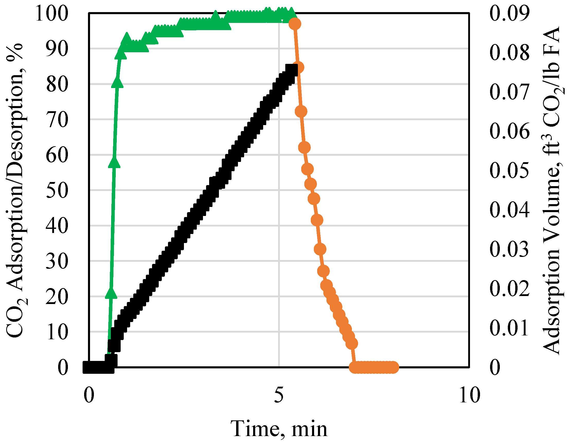
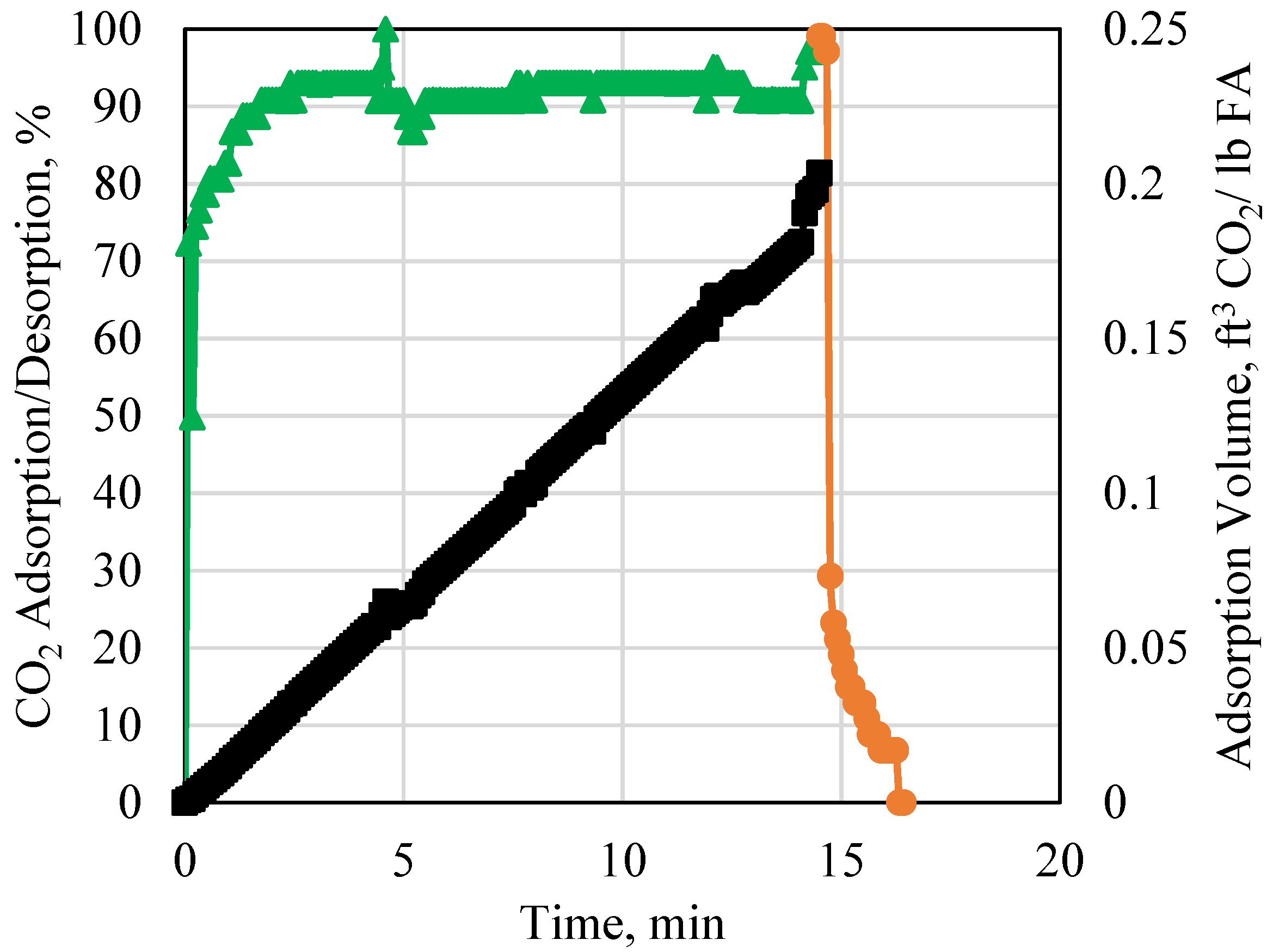
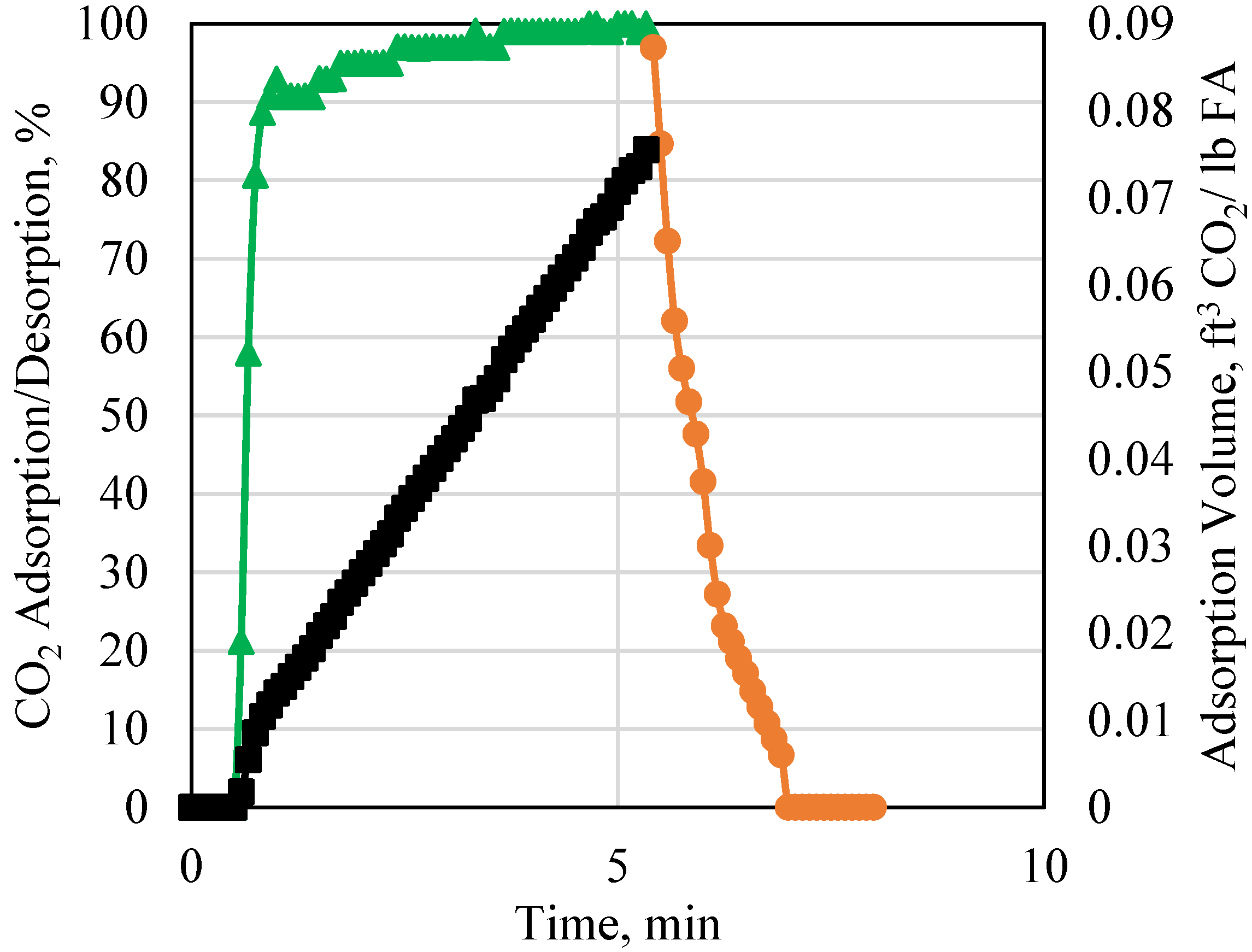
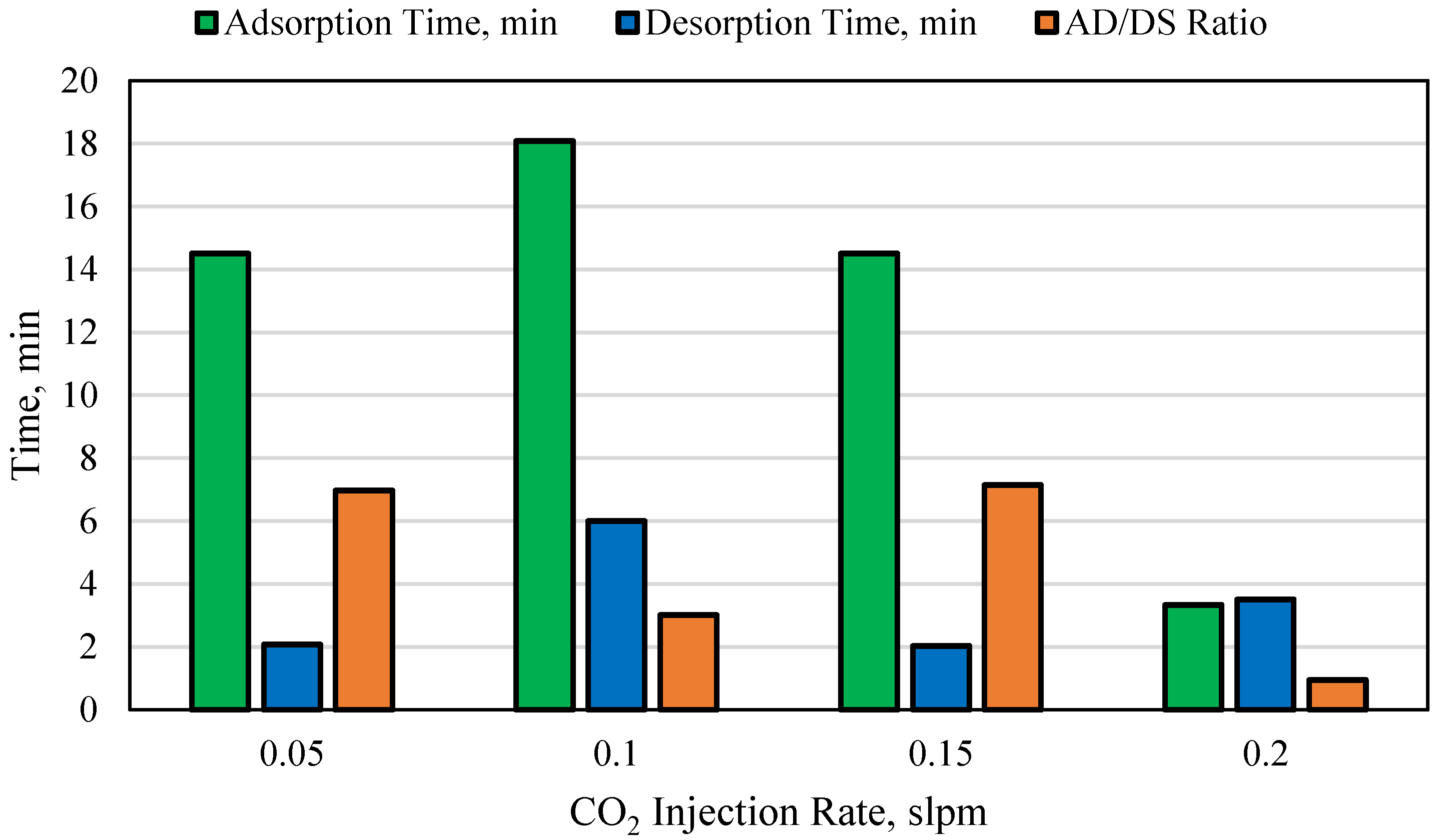
4.1. CO2 Injection Rate

The impact of varying CO2 injection rate on the adsorption capacity of the fly ash was investigated using a 0.05, 0.1, 0.15, and 0.2 slpm CO2 injection rate, shown in Figure 3. All experiments were conducted at 30 °C using the same volume and contact surface area of fly ash and a helium desorption rate of 3 slpm. For all experiments, CO2 adsorption occupied more than 90% of the available adsorption sites. At the lowest CO2 injection rate, 0.05 slpm, the lowest CO2 adsorption volume occurred. When the injection rate increased, the average adsorption volume increased significantly. At the highest injection rate of 0.2 slpm, an opposite trend was observed, where the adsorption rate decreased significantly. This shows a significant phenomenon, where increasing the CO2 injection rate will not necessarily be positive. A threshold injection rate signifies this point. When the rate is too low, the CO2 cannot extrude through all the available adsorption sites due to the equivalent low pressure. When the rate is too high, beyond the threshold rate, the CO2 flows too quickly over the surface of the fly ash. As mentioned previously, the type of adsorption taking place is physical adsorption, which is low energy. When the rate is too high, the bond energy between the adsorbent and the adsorbate is too weak compared to the rate at which the CO2 is flowing, hence reducing the adsorption potential. The adsorption time for all experiments was averaged at around 16 min, except for the highest rate which occurred very quickly due to the low adsorption volume.
It is important to note that increasing the CO2 injection rate will also result in an increase in the pressure. Although all experiments conducted were in low-pressure conditions, increasing the pressure will result in several key variations. These include a change in CO2 phase to supercritical if the temperature exceeds 31 °C. This can result in a significant change in the properties of the CO2, since supercritical CO2 will have a different density and viscosity compared to gaseous CO2. The increase in pressure will also result in significant compression of the fly ash. This can result in a smaller void space capacity, measured using helium. This will also impact the multi-layered CO2 adsorption due to the decrease in the overall adsorption sites. Finally, an increase in pressure will impact the flow of the CO2 molecules in the confined volume, especially if the pressure becomes too high to the point where the CO2 molecules begin repelling each other. High-pressure and high-temperature experiments are currently being conducted to evaluate the difference in results.

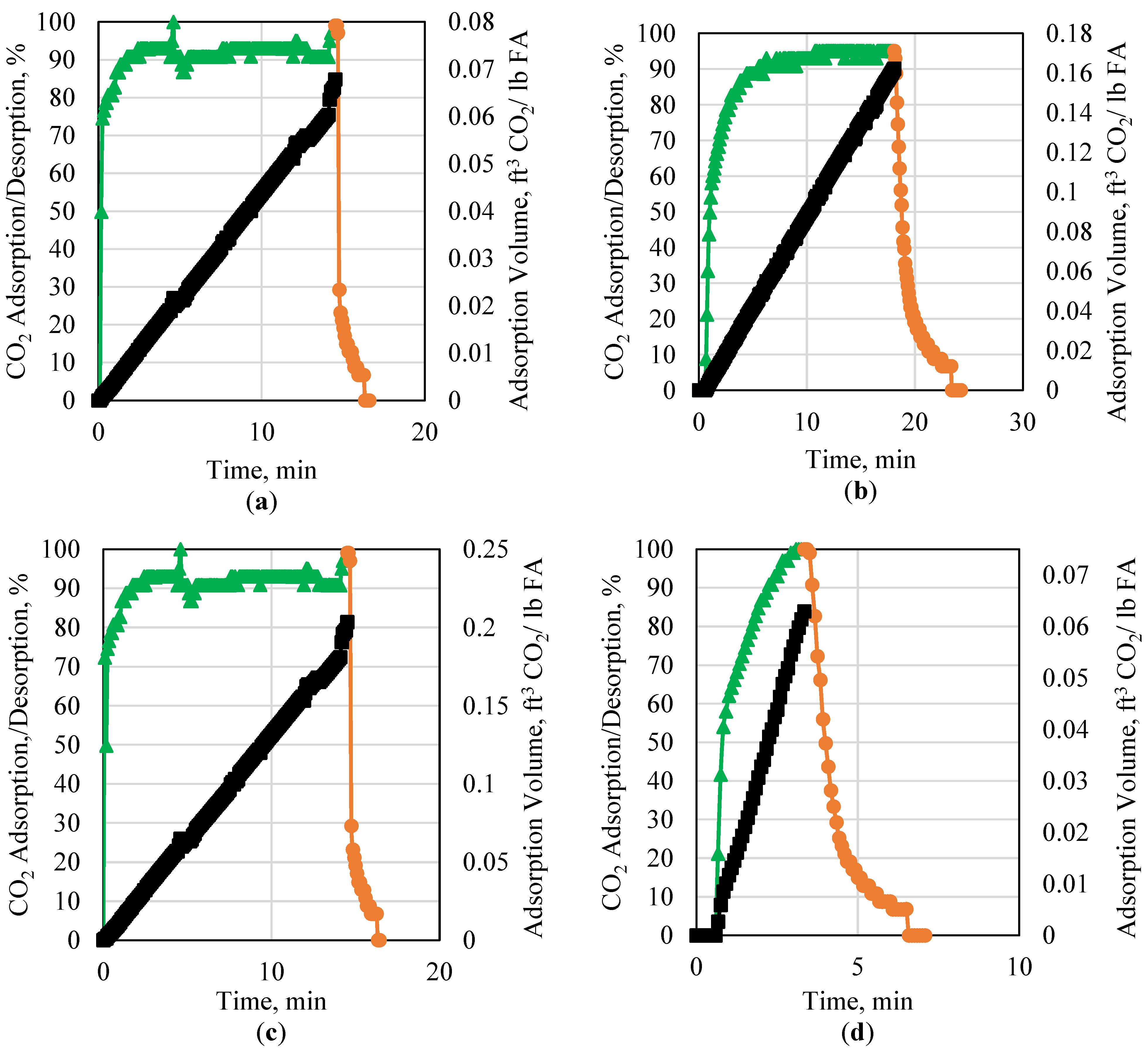
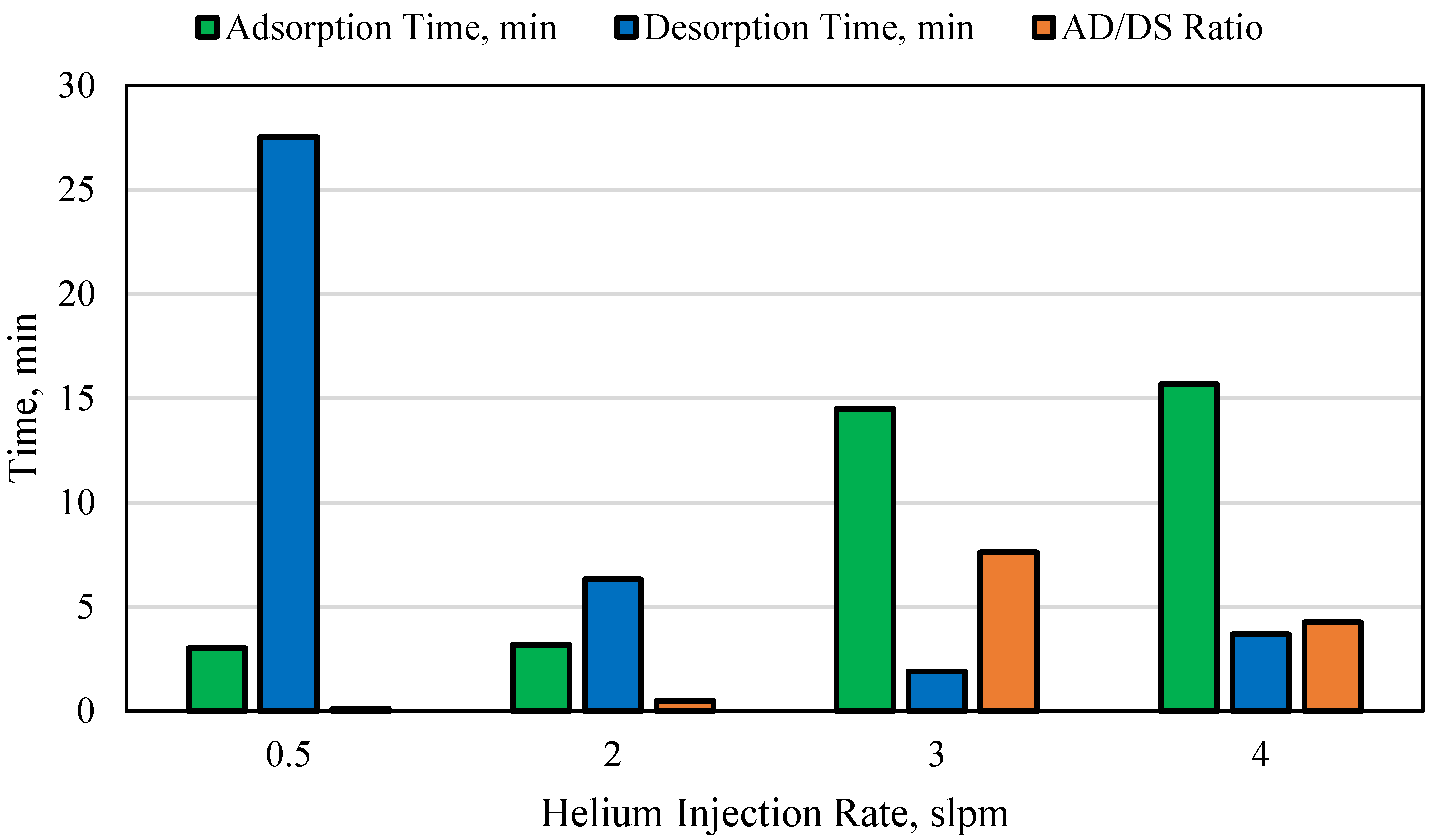
4.2. Helium Injection Rate

After adsorption, the CO2 stored can be desorbed for utilization in different industries. One of the main advantages of CO2 adsorption to fly ash is that it occurs via physical adsorption and thus the CO2 can be easily released. This research investigates the impact of the injection flowrate of helium as a desorbing gas after CO2 adsorption. Figure 4 presents the impact of the helium rate on the desorption of the CO2 using rates of 0.5, 2, 3, and 4 slpm. Increasing the helium injection rate resulted in a decrease in the time required for desorption. This is advantageous when quick CO2 desorption is required in order for a new adsorption cycle to take place. When the helium rate exceeded 3 slpm, however, the adsorption capacity of the CO2 was reduced, and the overall adsorption/desorption hysteresis cycle was prolonged. This is an important observation especially for physical adsorption, since it emphasizes the importance of observing the adsorption and desorption as a cycle rather than two separate processes. This also emphasized by the presence of an optimum point at which adsorption and desorption should take place as was the case for the CO2 injection rate experiments as well.

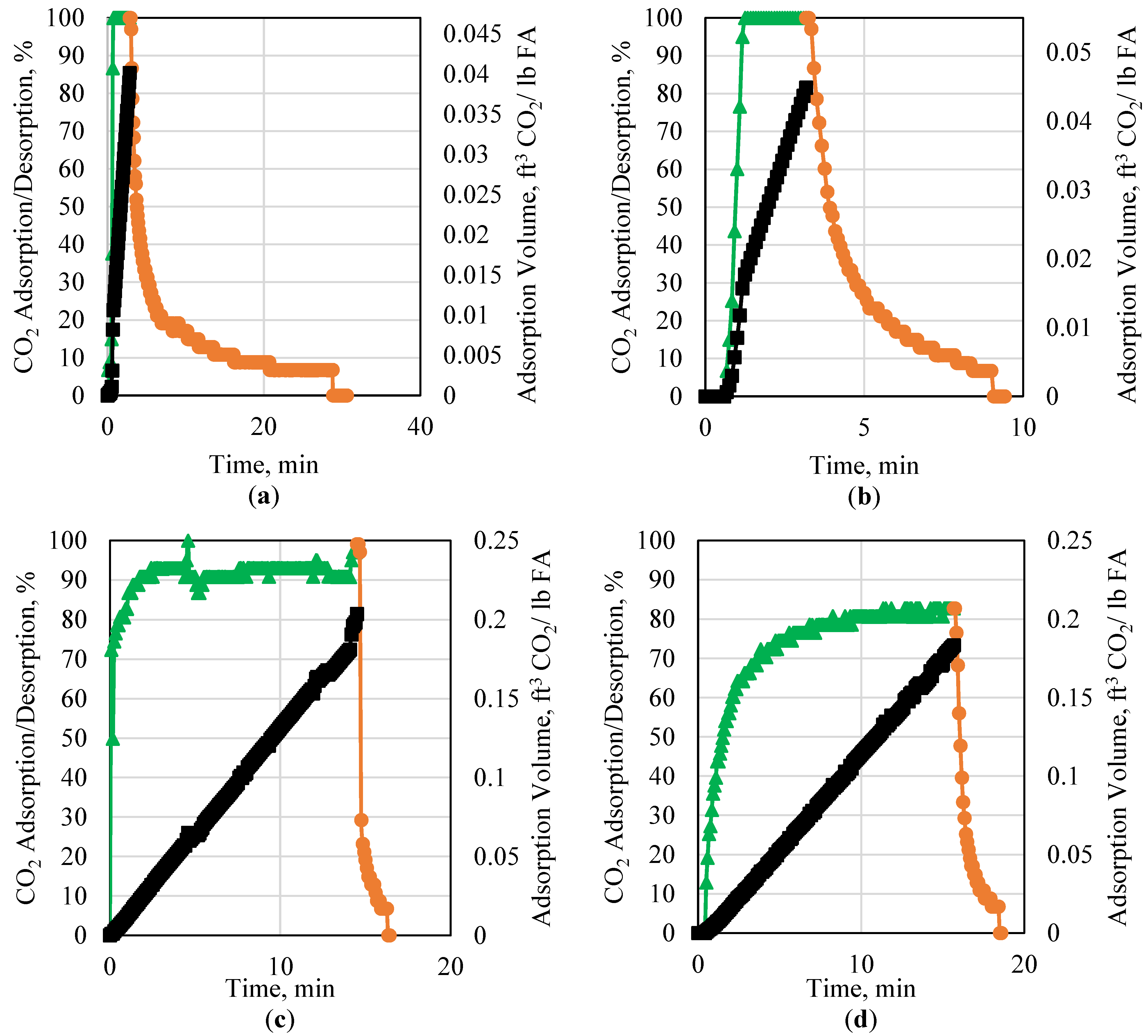
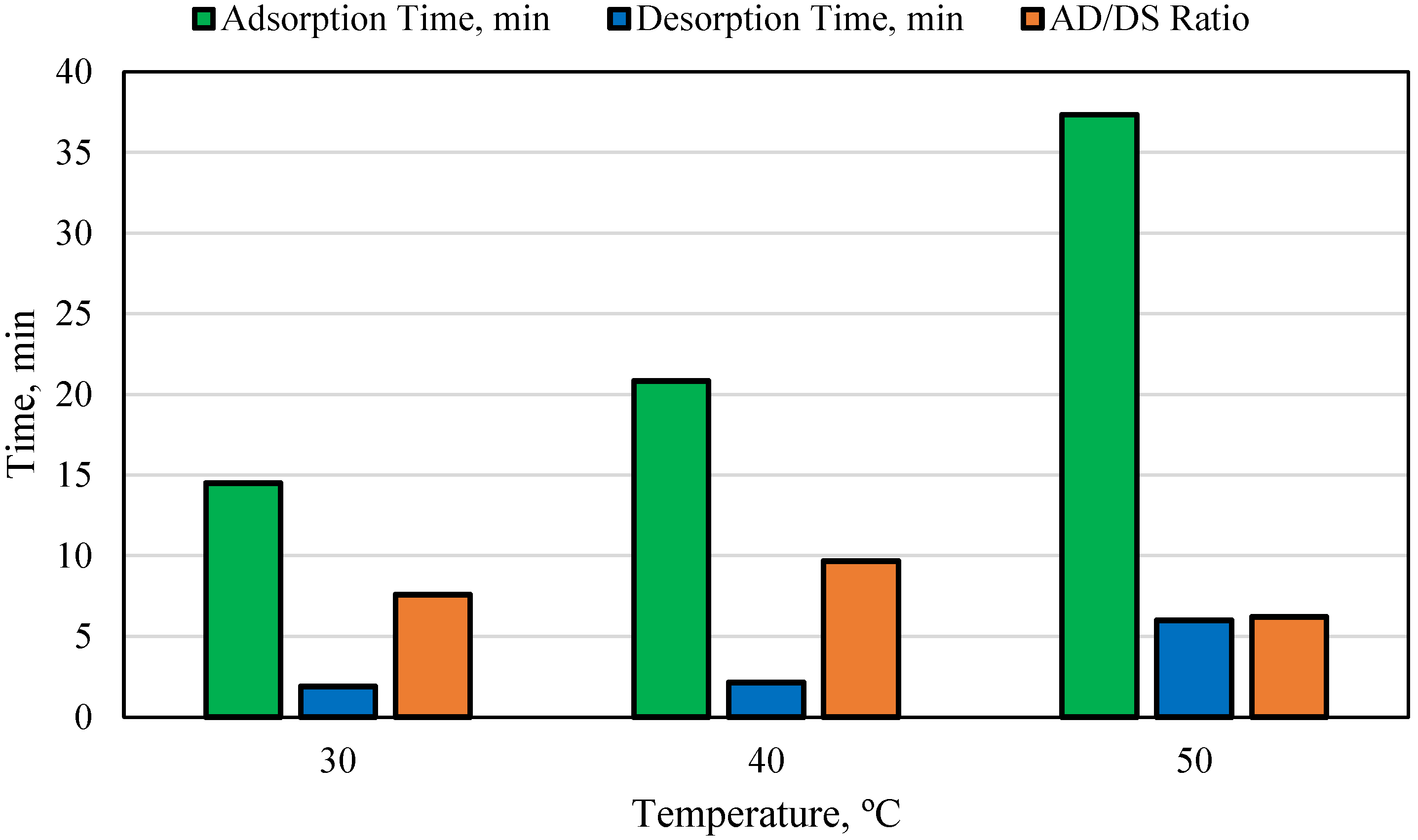
4.3. Fly Ash Temperature

The impact of the porous media temperature on CO2 adsorption was investigated using 30, 40, and 50 °C. All experiments were conducted using a 0.15 slpm CO2 injection rate using the same fly ash volume and identical CO2 adsorption sites’ availability. The results for the 30 °C experiments are presented in Figure 5. Similar to the previous experiment using the same conditions, the maximum adsorption capacity of the CO2 for the 30 °C experiment was 0.25 CO2 per pound of fly ash. Decreasing the temperature to 20 °C was also tested; however, no significant observation was made compared to the 30 °C experiment.
The CO2 adsorption capacity values using 40 °C and 50 °C are presented in Figure 6. As the temperature increased, the CO2 adsorption capacity also increased. The 40 °C experiment reached a maximum adsorption capacity of 0.32 CO2 per pound of fly ash, while the 50 °C experiment reached 0.58 CO2 per pound of fly ash. When further investigated, it was found that the increase in temperature resulted in the expansion of the fly ash particles which in turn resulted in an increase in the overall contact surface area between the fly ash and the CO2. This resulted in an increase in the potential adsorption sites available and thus an increase in the adsorption capacity. Another important observation is the sudden decrease in adsorption observed in the 40 °C and 50 °C experiments. This is due to the motion of the fly ash particles at elevated temperature which plugged the outlet of the setup thus impacting the readings of the detector.

4.4. Contact Surface Area between Fly Ash and CO2

The final parameter studied in this research is the impact of increasing the fly ash contact surface area with the CO2. It can easily be deduced that this will result in an increase in the increase in the CO2 adsorption capacity; however, it was important to investigate the extent of this increase. The CO2 adsorption capacity using a 708 cm2 surface area is shown in Figure 7, whereas the CO2 adsorption capacity using a 364 cm2 surface area is shown in Figure 8. The 364 cm2 surface area reached a maximum adsorption of 0.08 CO2 per pound of fly ash, while increasing the surface area to 708 cm2 resulted in an adsorption capacity of 0.25 CO2 per pound of fly ash. This shows that by almost doubling the contact surface area between the CO2 and the fly ash, the adsorption capacity increased by more than three times. This shows that a higher surface area is much better for a higher CO2 adsorption capacity for the same volume of fly ash and CO2.

5. Discussion

The CCUS initiative entails not only the capture of CO2 but also includes utilization of the fluid in different industries. In order for this occur, the CO2 must adsorb and desorb in a timely manner. The desorption process should be extremely quick to allow for another hysteresis cycle to initiate. Therefore, the ratio between the time to adsorption and the time to desorption, (AD/DS) should be as large as possible since this is an indication that the desorption time was minimal. The AD/DS ratio is calculated and plotted for all experiments conducted including the CO2 injection rate, the helium injection rate, and the temperature.
The adsorption time, desorption time, and the AD/DS ratio for the different CO2 injection rate experiments are presented in Figure 9. The highest adsorption time was for the 0.1 slpm experiment, whereas the lowest time was for the 0.2 slpm experiment. When observing the AD/DS ratio, however, the largest ratio was obtained for the 0.15 slpm experiment. This indicates that for all rate experiments conducted, this is the optimum. This can also be backed by the adsorption capacity of all rate experiments, where the 0.15 slpm had the highest CO2 adsorption volume. In comparison, the 0.2 slpm rate experiment had the lowest AD/DS ratio and also the lowest adsorption volume compared to the other rates.
Figure 10 shows the adsorption time, desorption time, and the AD/DS ratio for the different helium injection rates experiments. The lowest ratio value was for the lowest helium injection rate. This also corresponded to the lowest CO2 adsorption capacity. The highest value for the AD/DS ratio was at the 3 slpm helium injection rate, which corresponds to the highest adsorption volume of all the helium injection rate experiments. This indicates that exceeding the 3 slpm helium injection rate for this type of fly ash under the experimental conditions specified will result in a decrease in the adsorption capacity.
The adsorption time, desorption time, and AD/DS ratio for all three temperatures including 30, 40, and 50 °C are presented in Figure 11. Based on the results, the highest AD/DS ratio was for 40 °C, whereas the lowest value was for 50 °C. This shows no clear trend, since the highest CO2 adsorption volume was for 50 °C and thus should have corresponded to the highest AD/DS ratio. This could be explained through the analysis of the fly ash samples in the setup after the experiments. At elevated temperatures, some of the cubes began to break which resulted in a larger contact surface area for the CO2 and thus corresponded to a larger adsorption capacity. Due to the variation in the samples during the experiment, the adsorption time and the desorption time were inconsistent. This was evident from the abrupt decrease in the adsorption capacity during the 40 and 50 °C experiments due to blockage of the experimental setup.

6. Feasibility and Scalability of Fly-Ash-Based CO2 Capture

Fly ash is an extremely low-cost material that is produced as a byproduct of combustion. Therefore, utilizing fly ash in different applications is both highly feasible and also environmentally friendly since it incorporates the usage of a waste-material for beneficial applications. Fly ash has not yet been fully utilized as a carbon-capture material in large-scale applications due to several challenges. These include the following:
Compositional Variation in Fly Ash: Different fly ash will have different compositions depending on its origin. Based on this, the properties of the ash will vary, thus impacting the ability of the ash to adsorb CO2. This will, in turn, impact the CO2 capture capacity and capability of the fly ash.
Shaping of Fly Ash Particles: In order to shape the fly ash particle, geopolymerization is required. This involves an alkaline activator and water. The addition of these chemicals may impact the ability of the ash to adsorb CO2. Also, since different alkaline activators can be used, it is important to assess the impact of each separately.
Interaction with Water: Since fly ash is a pozzolanic material, it reacts with water to form a solid. This reaction impacts the available sites for adsorption on the surface of the ash, and thus impacts the overall CO2 adsorption capacity.
Selective Adsorption: One of the key points for any material that is used for CO2 adsorption is its ability to selectively adsorb CO2 in the presence of other gases. This requires extensive study due to the variable nature of fly ash and the chemicals used to treat it.

7. Limitations and Future Research Directions

This research focuses on low-pressure low-temperature CO2 capture using fly ash. The main limitations of this research include the usage of only one type of fly ash. Since different fly ash will vary in composition and structure depending on its origin, it is important to evaluate the performance of a variety of fly ash. Future directions for this research will therefore focus on testing multiple fly ash samples to determine the impact of several compounds and their concentration on the performance of fly ash. Another major direction is to test the performance of fly ash on CO2 adsorption in the presence of multiple gasses to assess the selectivity of fly ash to CO2.

8. Conclusions

This research studies the ability to improve CO2 storage in depleted underground reservoirs using fly ash via adsorption. The impact of the CO2 injection rate, temperature, and contact surface area between the CO2 and the fly ash on CO2 adsorption was studied. The main findings from this research are as follows:
  • Increasing the CO2 injection rate resulted in an increase in the adsorption capacity of the gas to the fly ash. The increase increased more than three-fold when comparing the lowest to the highest injection rates.
  • Increasing the temperature caused the fly ash to expand which resulted in an increase in the available adsorption sites. This in turn resulted in an increase in the CO2 adsorption capacity.
  • Decreasing the helium injection rate not only impacted the desorption, but also the adsorption capacity. At lower helium injection rates, the desorption process was extremely lengthy, while the adsorption capacity decreased significantly.
  • Doubling the contact surface area between the CO2 and the fly ash resulted in an increase in the CO2 adsorption capacity by more than three times, which indicated the significance of this factor on the overall CO2 storage capacity.

Author Contributions

Conceptualization, S.F. and A.K.; methodology, S.F. and A.K.; software S.F. and A.H.; validation, S.F. and A.K.; formal analysis S.F. and A.K.; investigation, S.F. and A.K.; resources, S.F., A.K. and A.H.; data curation, S.F. and A.K.; writing—original draft preparation, S.F. and A.K.; writing—review and editing, S.F.; visualization, S.F. and A.K.; supervision, S.F. and A.K.; project administration, S.F. and A.K.; funding acquisition, S.F. and A.K. All authors have read and agreed to the published version of the manuscript.

Funding

This research was funded by the Academy of Scientific Research and Technology (ASRT) in Egypt for funding this research project under the “ASRT Green Fund: Climate Change Adaptation and Nature Conservation” initiative, Project Title: Development of a Pozzolanic Super-Absorbent Saltwater Resistant Polymer for Pro-longed Carbon Dioxide Storage in Depleted Underground Reservoirs.

Data Availability Statement

Data are contained within the article.

Acknowledgments

The authors wish to thank the Academy of Scientific Research and Technology (ASRT) in Egypt for funding this research project under the “ASRT Green Fund: Climate Change Adaptation and Nature Conservation” initiative, Project Title: Development of a Pozzolanic Super-Absorbent Saltwater Resistant Polymer for Prolonged Carbon Dioxide Storage in Depleted Underground Reservoirs.

Conflicts of Interest

The authors declare that they have no conflicts of interest.

References

  1. Zhang, L.; Zhou, F.; Mou, J.; Feng, W.; Li, Z.; Zhang, S. An Integrated Experimental Method to Investigate Tool-Less Temporary-Plugging Multistage Acid Fracturing of Horizontal Well by Using Self-Degradable Diverters. SPE J. 2020, 25, 1204–1219. [Google Scholar] [CrossRef]
  2. Copeland, C.; McAuley, J. Controlling Sand with an Epoxy-Coated, High-Solids-Content Gravel Slurry. J. Pet. Technol. 1974, 26, 1215–1220. [Google Scholar] [CrossRef]
  3. Du, J.; Bu, Y.; Liu, H.; Shen, Z. Experimental Feasibility Study of a Novel Organic-Inorganic Hybrid Material for Offshore Oil Well Cementation. In Proceedings of the 28th International Ocean and Polar Engineering Conference, Sapporo, Japan, 10–15 June 2018. [Google Scholar]
  4. Huo, J.-H.; Peng, Z.-G.; Xu, K.; Feng, Q.; Xu, D.-Y. Novel micro-encapsulated phase change materials with low melting point slurry: Characterization and cementing application. Energy 2019, 186, 115920. [Google Scholar] [CrossRef]
  5. Fakher, S.; Fakher, A. Investigating the Use of CO2 as a Hydraulic Fracturing Fluid for Water Sustainability and Environmental Friendliness. In Proceedings of the SPE/IATMI Asia Pacific Oil & Gas Conference and Exhibition, Virtual, 12–14 October 2021. [Google Scholar] [CrossRef]
  6. Fakher, S.; Khlaifat, A.L. Experimental Investigation of Polymer Injection in High Permeability Conduits for Material Sustainability and Behavior in Oil Reservoirs. Polymers 2023, 15, 2950. [Google Scholar] [CrossRef] [PubMed]
  7. Kosek, J.R.; DuPont, J.N.; Marder, A.R. Effect of Porosity on Resistance of Epoxy Coatings to Cold-Wall Blistering. Corrosion 1995, 51, 861–871. [Google Scholar] [CrossRef]
  8. Leggat, R.B.; Zhang, W.; Buchheit, R.G.; Taylor, S.R. Performance of Hydrotalcite Conversion Treatments on AA2024-T3 When Used in a Coating System. Corrosion 2002, 58, 322–328. [Google Scholar] [CrossRef]
  9. Leggett, S.; Reid, T.; Zhu, D.; Hill, A.D. Experimental Investigation of Low-Frequency Distributed Acoustic Strain-Rate Responses to Propagating Fractures. SPE J. 2022, 27, 3814–3828. [Google Scholar] [CrossRef]
  10. Liu, B.; Li, Y.; Lin, H.; Cao, C.-N. Electrochemical Impedance Spectroscopy Study on the Diffusion Behavior of Water through Epoxy Coatings. Corrosion 2003, 59, 817–820. [Google Scholar] [CrossRef]
  11. Fakher, S.; Al-Sakkaf, A.; Ali, M. Evaluating key parameters impacting asphaltene permeability reduction behavior in micro-pores during carbon dioxide injection. Fuel 2023, 339, 126933. [Google Scholar] [CrossRef]
  12. Fakher, S. Development of novel mathematical models for laboratory studies of hydrolyzed polyacrylamide polymer injectivity in high-permeability conduits. J. Pet. Explor. Prod. Technol. 2020, 10, 2035–2043. [Google Scholar] [CrossRef]
  13. Fakher, S. Investigating the Factors Impacting the Success of Immiscible Carbon Dioxide Injection in Unconventional Shale Reservoirs: An Experimental Study (Order No. 27832893). ProQuest Dissertations & Theses Global. (2430974849). 2020. Available online: https://login.libproxy.aucegypt.edu/login?url=https://www.proquest.com/dissertations-theses/investigating-factors-impacting-success/docview/2430974849/se-2 (accessed on 3 October 2023).
  14. Khlaifat, A.L.; Fakher, S.; Harrison, G.H. Evaluating Factors Impacting Polymer Flooding in Hydrocarbon Reservoirs: Laboratory and Field-Scale Applications. Polymers 2023, 16, 75. [Google Scholar] [CrossRef]
  15. Khlaifat, A.; Fakher, S.; Ibrahim, A.D.; Elsese, M.; Nour, A. High-salinity produced water treatment and desalination. LHB 2023, 109, 2284957. [Google Scholar] [CrossRef]
  16. Shaughnessy, C.; Salathiel, W.; Penberthy, W.J. A New, Low-Viscosity, Epoxy Sand-Consolidation Process. J. Pet. Technol. 1978, 30, 1805–1812. [Google Scholar] [CrossRef]
  17. Singh, D.D.N.; Ghosh, R. Unexpected Deterioration of Fusion-Bonded Epoxy-Coated Rebars Embedded in Chloride-Contaminated Concrete Environments. Corrosion 2005, 61, 815–829. [Google Scholar] [CrossRef]
  18. Spinks, G.M.; Dominis, A.J.; Wallace, G.G. Comparison of Emeraldine Salt, Emeraldine Base, and Epoxy Coatings for Corrosion Protection of Steel During Immersion in a Saline Solution. Corrosion 2003, 59, 22–31. [Google Scholar] [CrossRef]
  19. Fakher, S.; Elgahawy, Y.; Abdelaal, H.; Imqam, A. What are the Dominant Flow Regimes During Carbon Dioxide Propagation in Shale Reservoirs’ Matrix, Natural Fractures and Hydraulic Fractures? In Proceedings of the SPE Western Regional Meeting, Virtual, 20–22 April 2021. [Google Scholar] [CrossRef]
  20. Yao, Z.T.; Ji, X.S.; Sarker, P.K.; Tang, J.H.; Ge, L.Q.; Xia, M.S.; Xi, Y.Q. A comprehensive review on the applications of coal fly ash. Earth-Sci. Rev. 2015, 141, 105–121. [Google Scholar] [CrossRef]
  21. Prasad, B.; Mondal, K. Environmental impact of manganese due to its leaching from coal fly ash. J. Environ. Sci. Eng. 2009, 51, 27–32. [Google Scholar]
  22. Kikuchi, R. Application of coal ash to environmental improvement: Transformation into zeolite, potassium fertilizer, and FGD absorbent. Resour. Conserv. Recycl. 1999, 27, 333–346. [Google Scholar] [CrossRef]
  23. Sun, L.; Li, D.; Pu, W.; Li, L.; Bai, B.; Han, Q.; Zhang, Y.; Tang, X. Combining Preformed Particle Gel and Curable Resin-Coated Particles to Control Water Production from High-Temperature and High-Salinity Fractured Producers. SPE J. 2019, 25, 938–950. [Google Scholar] [CrossRef]
  24. Shafeeyan, M.S.; Daud, W.M.A.W.; Houshmand, A.; Shamiri, A. A review on surface modification of activated carbon for carbon dioxide adsorption. J. Anal. Appl. Pyrolysis 2010, 89, 143–151. [Google Scholar] [CrossRef]
  25. Reddy, M.S.B.; Ponnamma, D.; Sadasivuni, K.K.; Kumar, B.; Abdullah, A.M. Carbon dioxide adsorption based on porous materials. RSC Adv. 2021, 11, 12658–12681. [Google Scholar] [CrossRef]
  26. Baltrusaitis, J.; Schuttlefield, J.; Zeitler, E.; Grassian, V.H. Carbon dioxide adsorption on oxide nanoparticle surfaces. Chem. Eng. J. 2011, 170, 471–481. [Google Scholar] [CrossRef]
  27. Chiang, Y.-C.; Juang, R.-S. Surface modifications of carbonaceous materials for carbon dioxide adsorption: A review. J. Taiwan Inst. Chem. Eng. 2017, 71, 214–234. [Google Scholar] [CrossRef]
  28. Guo, B.; Chang, L.; Xie, K. Adsorption of Carbon Dioxide on Activated Carbon. J. Nat. Gas Chem. 2006, 15, 223–229. [Google Scholar] [CrossRef]
  29. Saha, B.B.; Jribi, S.; Koyama, S.; El-Sharkawy, I.I. Carbon Dioxide Adsorption Isotherms on Activated Carbons. J. Chem. Eng. Data 2011, 56, 1974–1981. [Google Scholar] [CrossRef]
  30. Bonenfant, D.; Kharoune, M.; Niquette, P.; Mimeault, M.; Hausler, R. Advances in principal factors influencing carbon dioxide adsorption on zeolites. Sci. Technol. Adv. Mater. 2008, 9, 013007. [Google Scholar] [CrossRef]
  31. Mishra, A.K.; Ramaprabhu, S. Carbon dioxide adsorption in graphene sheets. AIP Adv. 2011, 1, 032152. [Google Scholar] [CrossRef]
  32. Hinkov, I.; Lamari, F.; Langlois, P.; Dicko, M.; Chilev, C.; Pentchev, I. Carbon Dioxide Capture by Adsorption (review). J. Chem. Technol. Metall. (JCTM) 2016, 51, 609–626. [Google Scholar]
  33. Zhang, Z.; Schott, J.A.; Liu, M.; Chen, H.; Lu, X.; Sumpter, B.G.; Fu, J.; Dai, S. Prediction of Carbon Dioxide Adsorption via Deep Learning. Angew. Chem. 2018, 131, 265–269. [Google Scholar] [CrossRef]
  34. Shafeeyan, M.S.; Daud, W.M.A.W.; Shamiri, A. A review of mathematical modeling of fixed-bed columns for carbon dioxide adsorption. Chem. Eng. Res. Des. 2014, 92, 961–988. [Google Scholar] [CrossRef]
  35. Li, J.-R.; Ma, Y.; McCarthy, M.C.; Sculley, J.; Yu, J.; Jeong, H.-K.; Balbuena, P.B.; Zhou, H.-C. Carbon dioxide capture-related gas adsorption and separation in metal-organic frameworks. Coord. Chem. Rev. 2011, 255, 1791–1823. [Google Scholar] [CrossRef]
  36. Yong, Z.; Mata, V.; Rodrigues, A.E. Adsorption of carbon dioxide at high temperature—A review. Sep. Purif. Technol. 2002, 26, 195–205. [Google Scholar] [CrossRef]
  37. Hassanpouryouzband, A.; Yang, J.; Tohidi, B.; Chuvilin, E.M.; Istomin, V.; Bukhanov, B.A. Geological CO2 Capture and Storage with Flue Gas Hydrate Formation in Frozen and Unfrozen Sediments: Method Development, Real Time-Scale Kinetic Characteristics, Efficiency, and Clathrate Structural Transition. ACS Sustain. Chem. Eng. 2019, 7, 5338–5345. [Google Scholar] [CrossRef]
  38. Panchal, S.; Debasis, D. Composite Cemented Backfill Based on Fly Ash, Bottom Ash and Mill Tailings. In Proceedings of the ISRM International Symposium—10th Asian Rock Mechanics Symposium, Singapore, 29 October–3 November 2018. [Google Scholar]
  39. Tosun, Y.I. Stabilization of Slope with Use of Coal Boiler Bottom Ash, Fly Ash and Geosynthethics for Bottom Seal Layer for Municipal Waste Landfill. In Proceedings of the ISRM 1st International Conference on Advances in Rock Mechanics—TuniRock 2018, Hammamet, Tunisia, 29–31 March 2018. [Google Scholar]
  40. Nyakilla, E.E.; Jun, G.; Charles, G.; Ricky, E.X.; Hussain, W.; Iqbal, S.M.; Kalibwami, D.C.; Alareqi, A.G.; Shaame, M.; Ngata, M.R. Application of Group Method of Data Handling via a Modified Levenberg-Marquardt Algorithm in the Prediction of Compressive Strength of Oilwell Cement with Reinforced Fly Ash Based on Experimental Data. SPE Drill. Complet. 2023, 38, 452–468. [Google Scholar] [CrossRef]
  41. Krstic, M.; Božovic, N.; Ðokovic, K. Stabilization of loess with fly ash. In Proceedings of the 5th Symposium of the Macedonian Association for Geotechnics, Ohrid, North Macedonia, 23–25 June 2022. [Google Scholar]
  42. Adewunmi, A.A.; Kamal, M.S. Performance Evaluation of Fly Ash as a Potential Demulsifier for Water-in-Crude-Oil Emulsion Stabilized by Asphaltenes. SPE Prod. Oper. 2019, 34, 820–829. [Google Scholar] [CrossRef]
  43. Adjei, S.; Elkatatny, S.; Sarmah, P.; Chinea, G. Investigation of Dehydroxylated Sodium Bentonite as a Pozzolanic Extender in Oil-Well Cement. SPE Drill. Complet. 2021, 36, 730–737. [Google Scholar] [CrossRef]
  44. Cella, P.A.; Taylor, S.R. Electrical Resistance Changes as an Alternate Method for Monitoring the Corrosion of Steel in Concrete and Mortar. Corrosion 2000, 56, 951–959. [Google Scholar] [CrossRef]
  45. Montemor, M.F.; Simões, A.M.P.; Ferreira, M.G.S. Analytical Characterization of the Passive Film Formed on Steel in Solutions Simulating the Concrete Interstitial Electrolyte. Corrosion 1998, 54, 347–353. [Google Scholar] [CrossRef]
  46. Cunningham, W.; Fehrenbach, J.; Maier, L. Arctic Cements and Cementing. J. Can. Pet. Technol. 1972, 11, PETSOC-72-04-06. [Google Scholar] [CrossRef]
Figure 1. CO2 adsorption experimental setup.
Gases 04 00007 g001
Figure 2. General plot for trend clarification.
Gases 04 00007 g002
Figure 3. CO2 adsorption/desorption at 30 °C using a 3 slpm helium desorption rate and using a CO2 injection rate of (a) 0.05 slpm, (b) 0.1 slpm, (c) 0.15 slpm, and (d) 0.2 slpm.
Gases 04 00007 g003
Figure 4. CO2 adsorption/desorption at 30 °C using a 0.15 slpm CO2 injection rate and using a helium desorption/injection rate of (a) 0.5 slpm, (b) 2 slpm, (c) 3 slpm, and (d) 4 slpm.
Gases 04 00007 g004
Figure 5. CO2 adsorption/desorption at 30 °C using a 0.15 slpm injection rate and 3 slpm helium desorption rate.
Gases 04 00007 g005
Figure 6. CO2 adsorption/desorption at (a) 40 °C and (b) 50 °C using a 0.15 slpm CO2 injection rate and 3 slpm helium desorption rate.
Gases 04 00007 g006
Figure 7. CO2 adsorption/desorption at 30 °C using 0.15 slpm rate and 708 cm2 surface area.
Gases 04 00007 g007
Figure 8. CO2 adsorption/desorption at 30 °C using a 0.15 slpm rate and 364 cm2 surface area.
Gases 04 00007 g008
Figure 9. Adsorption to desorption ratio at different CO2 injection rates.
Gases 04 00007 g009
Figure 10. Adsorption to desorption ratio at different helium injection rates.
Gases 04 00007 g010
Figure 11. Adsorption to desorption ratio at different temperatures.
Gases 04 00007 g011
Disclaimer/Publisher’s Note: The statements, opinions and data contained in all publications are solely those of the individual author(s) and contributor(s) and not of MDPI and/or the editor(s). MDPI and/or the editor(s) disclaim responsibility for any injury to people or property resulting from any ideas, methods, instructions or products referred to in the content.

