Abstract
The demand for mineral resources has dramatically increased over the past few decades; this increase directly correlates to an increase in underground mining activity. There are different mining methods for different minerals, and each have their risks. In hard rock mining activities such as mining for gold, rockfalls are the most significant deterrent to obtaining mineral resources. This paper focuses on rock reinforcement systems to prevent fatal rockfalls in underground excavations. Presently, there is a global steel shortage and an increase in prices that has impacted the productivity of the mining operations that support most national economies. The paper’s main objective is to present the improvement of a rock bolt design used to support the roof in underground mining activities and keep working personnel and equipment safe from rockfalls. This study presents two rock bolt designs: a preliminary design and an improved model of the rock bolt. The paper discusses the operation of the rock bolt and provides laboratory test results on the bolt in operation. The principle of operation of the yield bolt is based on the science of radial expansion of hollow tubes in tension, to provide integrity to underground excavations. This functional design of the rock bolt requires less steel and has the same performance as the current rock reinforcement elongates. The research methodology involved interviewing rock mining engineers to determine their desired rock reinforcement device that would adequately meet the unpredictable dynamic and static behavior of underground rocks. The methodology also included experimental tests of a rock bolt design that was aimed at meeting the desired and acceptable performance determined from the interviews. The experimental results were obtained from a 60-ton hydraulic press that simulated seismic activity underground. The experimental results showed several modes of failure for the bolt; however, the improved rock bolt yielded at an average of 200 kN, as designed. During testing of the preliminary bolt design, there were failures that resulted from the manufacturing process of the bolt, such as splitting of the tube due to the welded end components. After a dynamic test, the preliminary bolt tube bent, creating huge forces on the tube which may cause fracture. The coefficient of friction during dynamic testing was lower than during static testing, leading to undesirable results for the preliminary bolt. The optimized bolt design addressed the failures and the low yield tonnage of the preliminary bolt design. It successfully yielded at 20 tons, even during the dynamic event. The bolt had similar alignment issues which caused failure during testing, as can be seen from the results. A guide tube was implemented in the design and the manufacturing process changed; these changes resulted in the bolt having a more reliable performance that met the requirements throughout.
1. Introduction
During the 20th century, there have been tremendous developments in technological devices. These developments have aided the exponential growth of world economies and rapid industrialization throughout the globe [1]. The development of these technological devices requires mineral resources to be extracted from the earth, raising the demand for mineral resources worldwide. Hence, mines must excavate minerals at greater depths than ever before [1]. The top three deepest underground excavations are for gold mining and are found in South Africa. Mponeng mine, at a depth of 3.84 km, is the deepest, followed by Driefontein and Kusaselethu mines at 3.42 km and 3.38 km deep, respectively [2]. Mining activities at these depths give rise to very high safety concerns for working personnel and machinery. An adequate rock reinforcement system is required to ensure safety for working personnel and the equipment used.
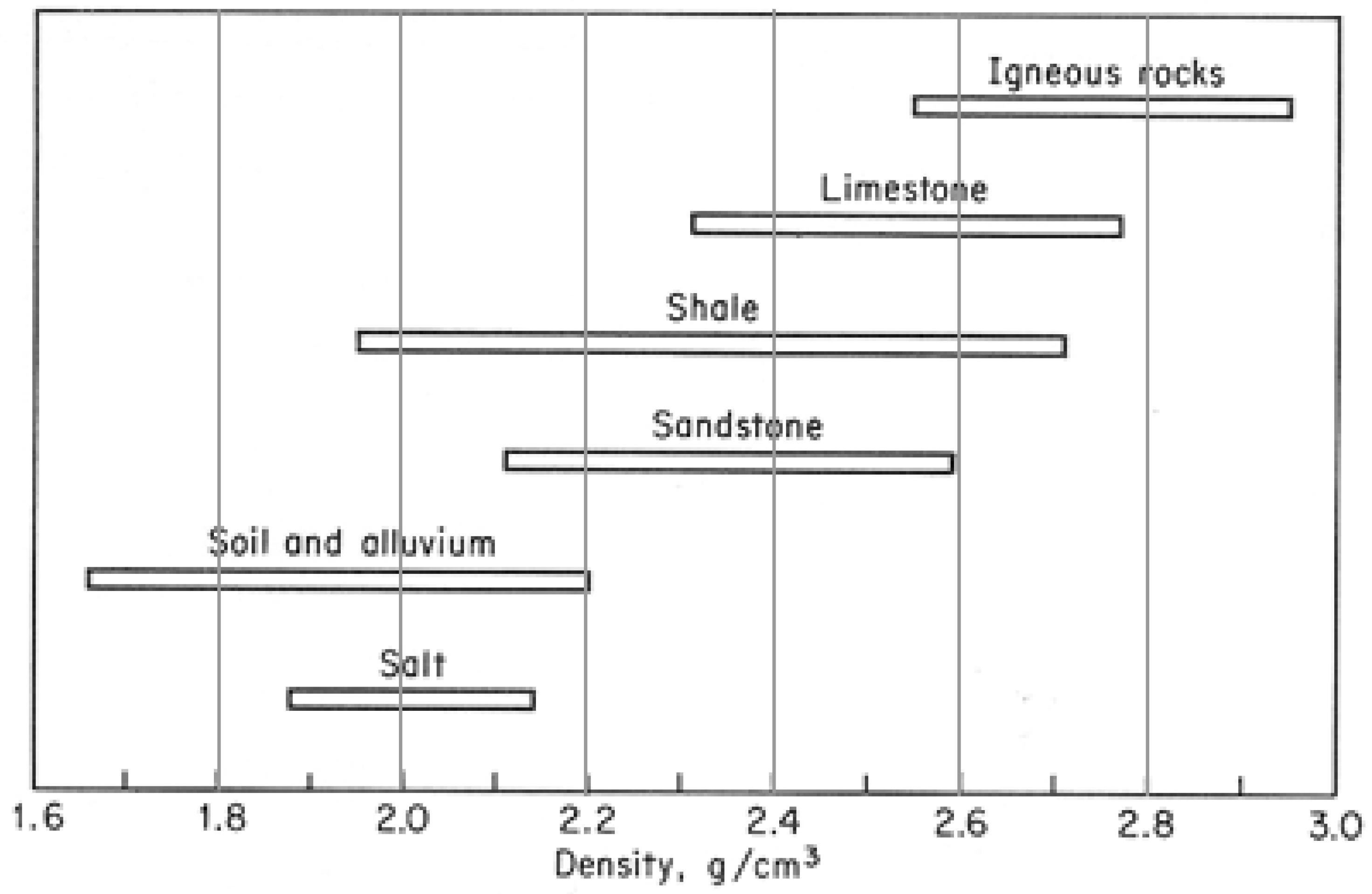
There are three main rock types, namely: igneous, metamorphic, and sedimentary rocks. The exploration and excavation of igneous and metamorphic rocks are termed hard rock activities, due to the rocks’ metalliferous mineral content, making them generally harder than sedimentary rocks which contain oil, natural gas, or coal. The exploration and excavation activity within sedimentary rocks is termed soft rock mining. Limestone and shale are sedimentary rocks; granite and gneiss are igneous and metamorphic (crystalline) rocks. Calcite and marble are found in limestone and are also significantly hard, as is quartz in sandstone. These are outliers in soft rock mining. Figure 1 shows the densities of different rock types, with increasing hardness on the y-axis.
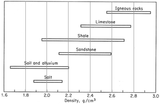
Figure 1.
Density of various rock types [3].
This paper focuses on the products available in South Africa to reduce fatalities and injuries due to rockfalls in underground mining. The rock reinforcement market is saturated with support systems that hinder the working space of miners and machinery. The available roof anchors are difficult and time-consuming to install, have unsuitable load-bearing characteristics or have too many variables that make it hard to achieve proper and sufficient installation. This paper presents a rock bolt concept developed by [4] at the Mine Support Products (MSP) company in Johannesburg, South Africa. It addresses the shortcomings of the preliminary rock bolt design reported by [4], after testing, and presents an improved rock bolt design, together with the bolt’s performance results from the research and development department at MSP. This paper briefly discusses the currently used rock reinforcement devices in South Africa and further elaborates on the product development of a rock bolt for underground hard rock mining. This study aims to increase the safety of mine workers underground and ensure the continual production of gold that supports the South African economy.
There are several rock bolts currently available on the market and used for roof reinforcement; their shortcomings are low yield tonnage, low ultimate tensile strength, and small yield length. The rock bolts have become less effective as mining depth has increased, as deep mines require high-load-bearing reinforcements [5]. The performances of these rock bolts are fully discussed in Section 2.3.1.
During underground visits to investigate new technological devices for use in rock reinforcement, it was observed that the deeper one goes, the more the available resources for rock reinforcement are lacking. Thus, mining activities at greater depths become more dangerous. Under these difficult conditions, mine workers still need to retrieve mineral resources at a profitable rate. The motivation for this research is therefore to make available a reliable solution to keep mine workers safe, which is the priority of the mine regardless of all other resources that ensure that the productivity of mine workers is efficient. The rockfall risk evaluation conducted showed that the deeper one goes, the higher the contrast between the mining standards set by management and the reality. This paper therefore contributes to the safety aspect of underground mining practices via the design of rock bolts to support the roof of the excavation tunnels.
2. Mining Activity
There are three types of mining operations employed to retrieve minerals [6]. These are open pit, underground, and underwater mining. Open pit and underwater mining operations occur with the working personnel above ground or water. Machines generally lead both these mining operations with humans operating at a safe distance to retrieve the mineral ores. Underground mining operations require strategic mining methods, which generally involve manual labor to extract rich mineral ores. The fatalities and injuries experienced in open pit and underwater operations are generally due to poor working ethos with regard to legislature, maintenance, or operations, or to human error. Underground mining requires many active personnel to facilitate the extraction of mineral ores, and the major cause of fatalities and injuries in this type of mining is rockfalls [7].
2.1. Underground Mining Operations and Related Fatalities
Different minerals require different mining methods. Therefore, due to the different characteristics of the rock sediments, different rock reinforcements are used in these operations to ensure they are safe for workers. There are five methods of underground mining; the method applied depends on the type of rocks (soft or hard) [6]:
- (a)
- Room and pillar—coal—soft rock.
- (b)
- Narrow vein stoping—platinum—hard.
- (c)
- Short and longwall mining—coal—soft.
- (d)
- Sub-level caving—diamonds and gold—hard.
- (e)
- Block caving—copper—soft.
Most mining accidents occur in third world countries; coal mining in China is considered the world’s deadliest, with a mean fatality rate of 13 miners per day [8]. The fatalities are mainly attributed to consecutive explosions of coal dust containing methane, which is a very volatile, explosive, and poisonous gas. The United States of America had a mean of 30 coal mining fatalities per year between 2001 and 2005 [9]. The high fatality rate in the coal mining industry is firmly attributed to the presence of high volatile gas concentrations and elimination of igniting sources in a highly flammable environment [10], it is not structural failures in the mining methods involved in this environment.
Underground soft rock mining includes a group of underground mining techniques used to extract coal, oil shale, potash, and other minerals or geological materials from sedimentary (“soft”) rocks. Because deposits in sedimentary rocks are commonly layered and are relatively less hard, the mining methods used differ from those used to mine deposits in igneous or metamorphic rocks. Soft rock underground mining methods are considered structurally safer than hard rock methods. Underground hard rock mining refers to various underground mining techniques used to excavate “hard” minerals, usually those containing metals, such as ores containing gold, silver, iron, copper, zinc, nickel, tin, and lead. It also involves the same techniques used to excavate ores of gems, such as diamonds and rubies.
There is great potential for rockfalls and mining-induced seismic activity in underground hard rock mining. As of December 2017, statistically, 37% of fatalities were caused by fall of ground in South African mines [11]. The pie chart in Figure 2 depicts this.
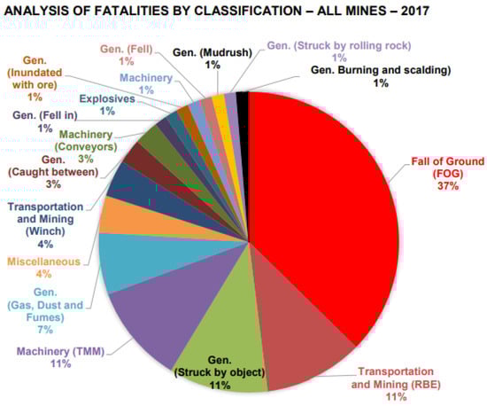
Figure 2.
Analysis of fatalities by classification [11].
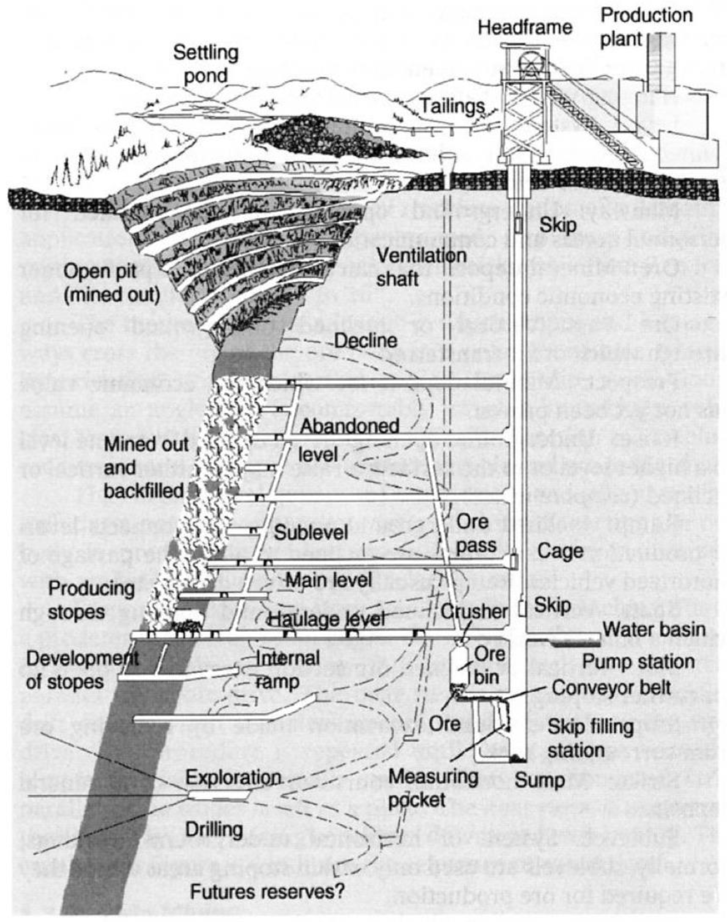
Sub-level caving remains the most widely used method for hard rock mining and involves blasting activity to retrieve mineral ores. Figure 3 shows the sub-level caving mining method used for hard rocks. On the producing stope, caved-out sections within the mineral can be seen in Figure 3. These caved-out sections are where blasting activity has occurred in search of high-grade mineral ores.

Figure 3.
Sub-level caving for gold mining [12].
In the statistics, 80% of the reported fatalities were from hard rock mines only. Fall of ground accounted for 16.7% of injuries in the December 2017 report and was also the largest cause of injuries [11].
2.2. Rockfalls in Hard Rock Mining
There are two causes of rockfalls underground: rock bursts and rockfalls due to gravity. Rock bursts are a result of high-stress zones within the rock morphology. These high-stress zones develop due to high blasting activity underground to retrieve high-grade mineral ores [7]. The energy dissipated from blasting creates vibrations in the rock morphology, causing high-stress zones and inducing seismic activity [7]. Rock bursts occur along rock fault lines, joints, and in the presences of dykes. The size of the underground excavation influences both types of rockfall; the more extensive the excavation, the higher risk of rockfalls, and those due to gravity are more common in deep-level mining areas due to the heavy weight of the ground above. One or more of three situations must be present for a rockfall to occur [7]:
- (a)
- Rocks are falling where there is no support.
- (b)
- Rocks are falling between supports.
- (c)
- Rockfalls occur due to the failure of the installed support system.
2.3. Rock Reinforcement
Geophones are susceptible geotechnical sensors that monitor seismic activity underground. These are installed underground in the hanging wall to monitor the gradual downward movement of the ground above within a stope [13]. The geophones warn miners of rock movements above them and initiate evacuation and the necessary safety precautions. Figure 4 shows the fall of ground light geophone manufactured by New Concept Mining, Johannesburg, South Africa. This is a monitoring device.
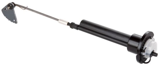
Figure 4.
New Concept Mining fall of ground light geophone [14].
Blasting occurs at the stope, which is located at the end of the hanging wall. After every blasting session, an unsupported hanging wall is exposed that needs to be cleared of the rumble (mineral ores). This is then transported to the head frame for processing [12]. This exposed hanging wall accounts for most of the rockfall fatalities underground because working personnel need to clear the rumble and support the hanging wall concurrently until they reach the next stope to be blasted. To ensure a safer hanging wall for active personnel underground, adequate support must be installed. There are different types of reinforcement mechanisms on the market [15]. The support chosen depends on the rock characteristics, the mining method, and the financial resources of the mining operations. There are two types of supports: permanent and temporary, and within these types are various design mechanisms applicable to different mining environments. When a support is installed, it needs to be pre-stressed in order to apply an upward force to the downward falling roof. Highly pressurized water and air are used to pre-stress support devices.
2.3.1. Types of Rock Bolt Reinforcement Available
There are three main sub-categories of rock bolts [16]:
- (a)
- Continuously mechanically coupled (CMC)—fully grouted (cement or resin) and D-bolt.
- (b)
- Continuously frictionally coupled (CFC)—inflated steel tube.
- (c)
- Discretely mechanically or frictionally coupled (DMFC)—expansion-shell type.
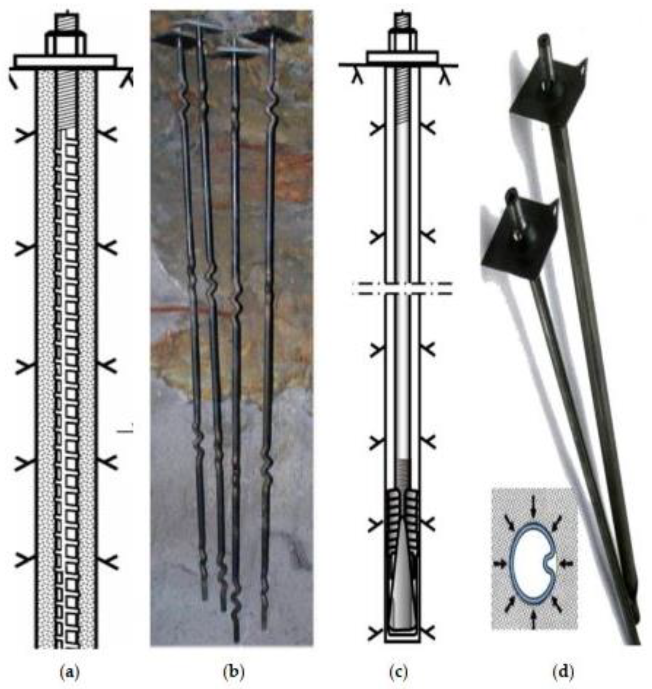
Figure 5 shows the different types of rock bolts available [16]. Rock bolts “a” and “b” are fully grouted and D-bolt, falling under the CMC category. CMCs are stiff and provide high load bearing due to their mechanical interlocking characteristics during static ground movement. However, during dynamic ground deformation, they perform poorly. Nonetheless, this is the most widely used bolt in underground mining excavations [16]. The performance of fully grouted rock bolts depends on the quality of the cement or resin mixture. For resin-grouted bolts, cartridge accumulation occurs at the borehole end and decreases their efficiency. This accumulation is due to insufficient resin mixing at the borehole end. The optimal resin mix and bolt encasement occur at the middle of the bolt, making it perform unreliably at its full capabilities. Resin-grouted bolts provide more advantageous mechanical properties than cement [16]. For cement-grouted bolts, the water-to-cement ratio influences their strength; the setting time for cement-grouted bolts means that they are less reliable for immediate support in high-stress and volatile areas [16].

Figure 5.
Types of rock bolts [16].
Rock bolts “c” and “d” are DMFC and CFC types, respectively; they are flexible and capable of absorbing large ground deformations at varying loads [16]. The installation procedure involves inserting the rock bolt into the borehole and pre-stressing it by tensioning the rear end nut. All rock bolts are permanent supports. For mild rock burst environments, device “d” is widely used. When used with mesh, the rock bolt will slip rather than rupture and retain the rock burst. The maximum size of CFCs available is 46mm, and ultimate failure occurs at 16.3 tons. This remains too low for their application in underground mining at great depth.
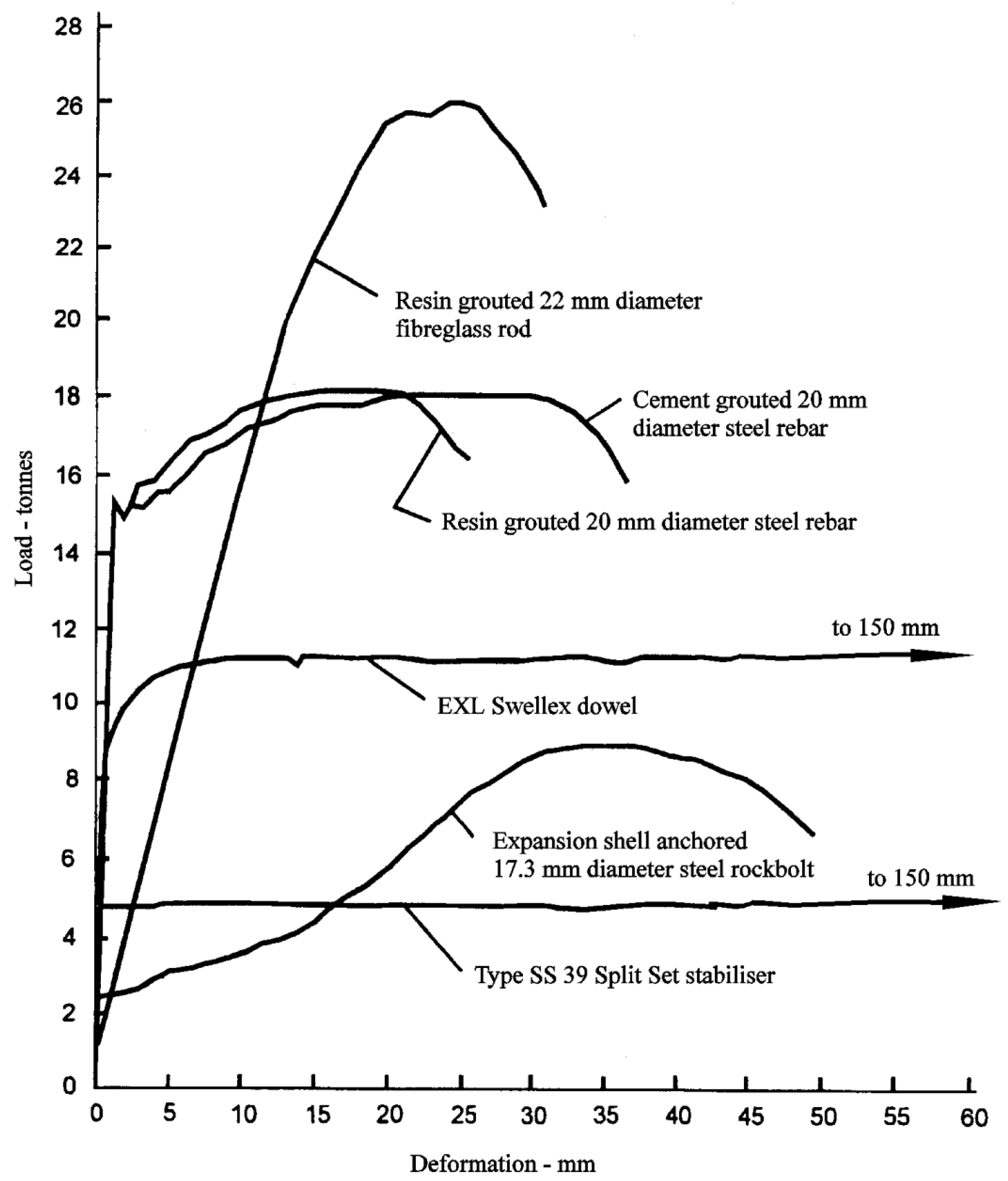
Test blocks of highly reinforced concrete were created in order to investigate the load deformation characteristics of available rock bolts used in the mining industry.The test blocks had a uniaxial compressive force of 60 MPa. Various rock bolts were installed inside the test blocks, following the standard instructions for installation used undergroud [15]. The load–deformation characteristics are show in Figure 6 were as follows:

Figure 6.
Load–deformation characteristics of rock bolts on the market [15].
- (a)
- Resin-grouted 20 mm diameter steel rebar. With a load of 15 tons and an elastic deformation of about 1.5 mm, hot-rolled reinforcing steel is characterized by a sharp drop in load. The maximum load is 18 tons with a deformation of 20 mm. Resin is stronger than mortar, and local breakage and bond failure is limited compared to grout reinforcement, resulting in lower final displacement when the reinforcement fails.
- (b)
- Expansion-shell anchored. At a pre-tension of 2.25 tons, the faceplate is not deformed. Under a load of 4 tons, the frame is deformed by 9.5 mm, becoming completely flat, and the propeller shaft is deformed by another 3.5 mm, giving a total deformation of 13 mm under a load of 4 tons. Failure begins with a load of 8 tons and a deformation of 25 mm, with gradual failure of the expansion anchor where the cone is pulled through the wedge. The maximum load is 9 tons with a deformation of 35 mm.
- (c)
- Cement grouted rebar. With a load of 15 tons and an elastic deformation of about 1.5 mm, hot-rolled reinforcing steel is characterized by a sharp drop in load. The maximum load is 18 tons with a deformation of 30 mm.
- (d)
- Resin-grouted fiberglass rod. With a load of approximately 1.5 tons, the glass fiber/resin interface begins to crack and spread along the rod. As the breakdown of the bond progresses, the glass fiber rod deforms, increasing its “free” length. A typical bond breakage occurs with a load of approximately 26 tons and a deflection of 25 mm. The tensile strength of this assembly is determined by the bond strength between the resin and the glass fiber rod and the relatively low frictional resistance of the glass fiber.
- (e)
- Split set stabilizer, type SS-39. The pin begins to slip at about 5 tonnes and holds this load throughout the test, which in this case led to a total displacement of 150 mm.
- (f)
- EXL Swellex dowel. At a load of 5 tons, the pin begins to locally deform at the joint, and at the same time, at the joint, the ‘bond breaks’ and, with increasing load, extends outside the joint. Complete destruction of the bond occurs at 11.5 tons with a deformation of about 10 mm. The pin starts to slip under this load and withstands the load during the entire test, with a displacement of 150 mm.
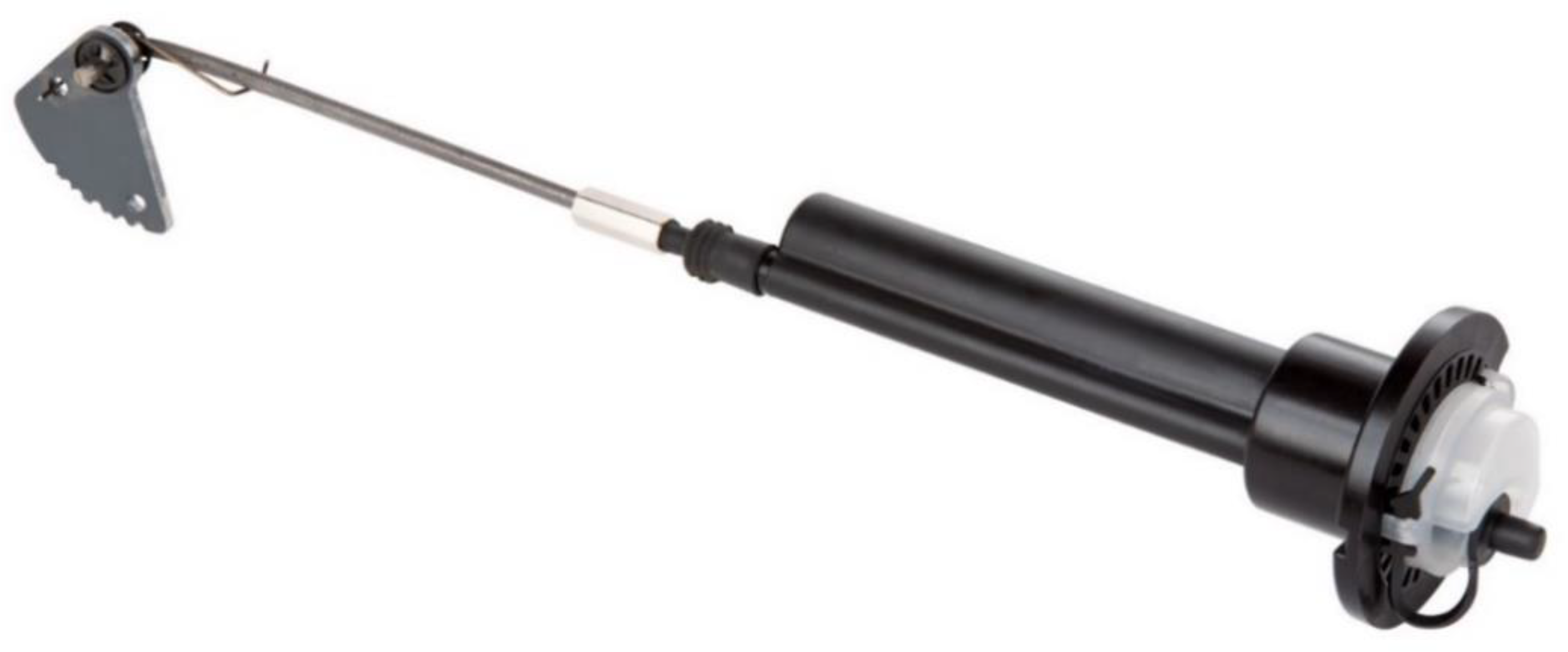
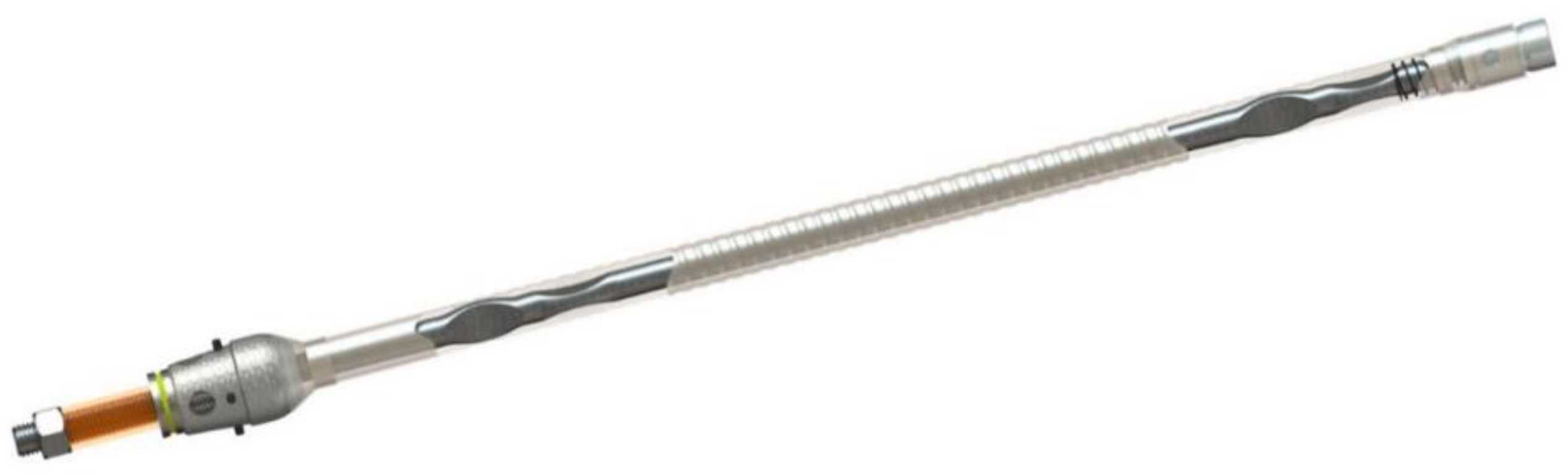
The New Concept Mining MP1 rock bolt manufactured in Johannesburg, South Afrcia is shown in Figure 7, it is a permanent support that starts to yield at 15 tons. It is pre-stressed using a hydraulic hand pump and drilled into the hanging wall. It is a DMFC rock bolt. This rock bolt starts to yield at 15 tons and has a typical tensile stress of 22.5 tons [17]. At greater depths, the required acceptable yielding average is 20 tons as per the product specification requirements from [18] the interviews with stakeholders. The failure of the bolt at 20 tons causes rock bursts underground due to the sudden release of the energy the bolt was absorbing.

Figure 7.
New Concept Mining MP1 rock bolt [17].
2.3.2. Other Types of Rock Reinforcement
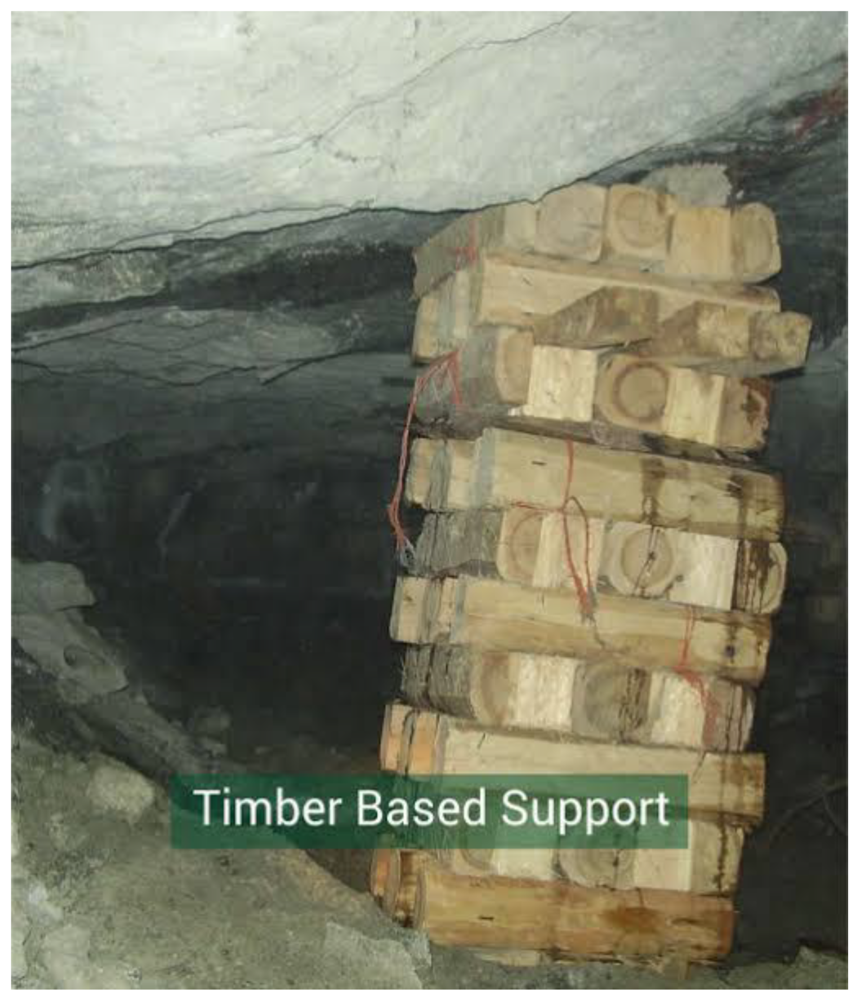
Timber and cement packs are permanent supports with high yield force used in any mining environment with adequate space. A jack pack is placed under the support pack and pressurized until it inflates to achieve the pre-stressing necessary to ensure a sufficient upward force is exerted by the support pack (Figure 8) on the roof.
This support provides no dynamic-load-bearing support, takes time to install and is difficult to install while ensuring it is firmly pre-stressed, due to the unevenness of the floor and roof. Footplates are available to place under support devices [19], there are no footplates large enough for packs.
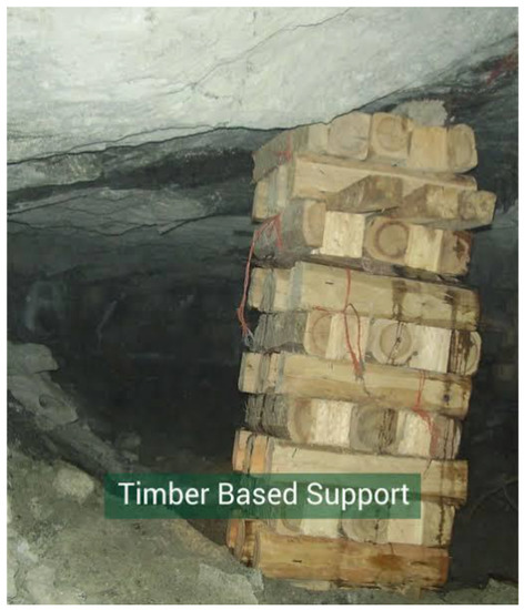
Figure 8.
Bedrock timber-based support pack [20].
Figure 8.
Bedrock timber-based support pack [20].
The Timrite prop shown in Figure 9 can be used both temporarily and permanently. It uses a cam follower for pre-stressing and a pin to lock it in place at a specific height. Lower yield tonnages for areas with stable rock characteristics are achieved. The prop does not have dynamic-load-bearing characteristics due to the pin used for locking it in place.

Figure 9.
Timrite cam and pin prop [21].
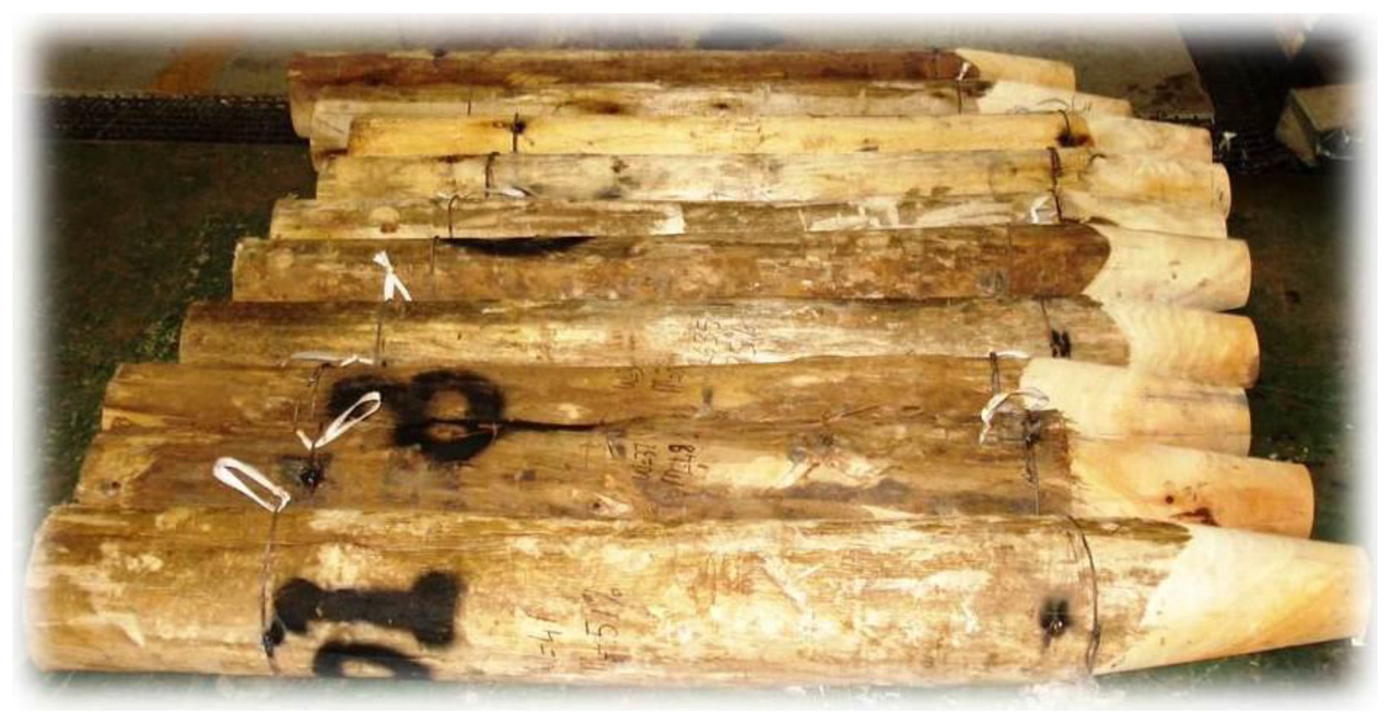
The Timrite pencil prop, a timber-based permanent support, uses a jackpot for pre-stressing and has high yield tonnage, with no possibility of adjusting the height of the prop (Figure 10). The props are of a fixed height, with slight variations in height as the roof underground is uneven. It is difficult find the exact height required for the pencil prop and to install the props in a sufficiently pre-stressed state. During dynamic testing, the wood fibers split, resulting in an immediate drop in the dynamic-load-bearing capability [22].
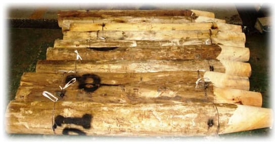
Figure 10.
Timrite pencil prop [21].
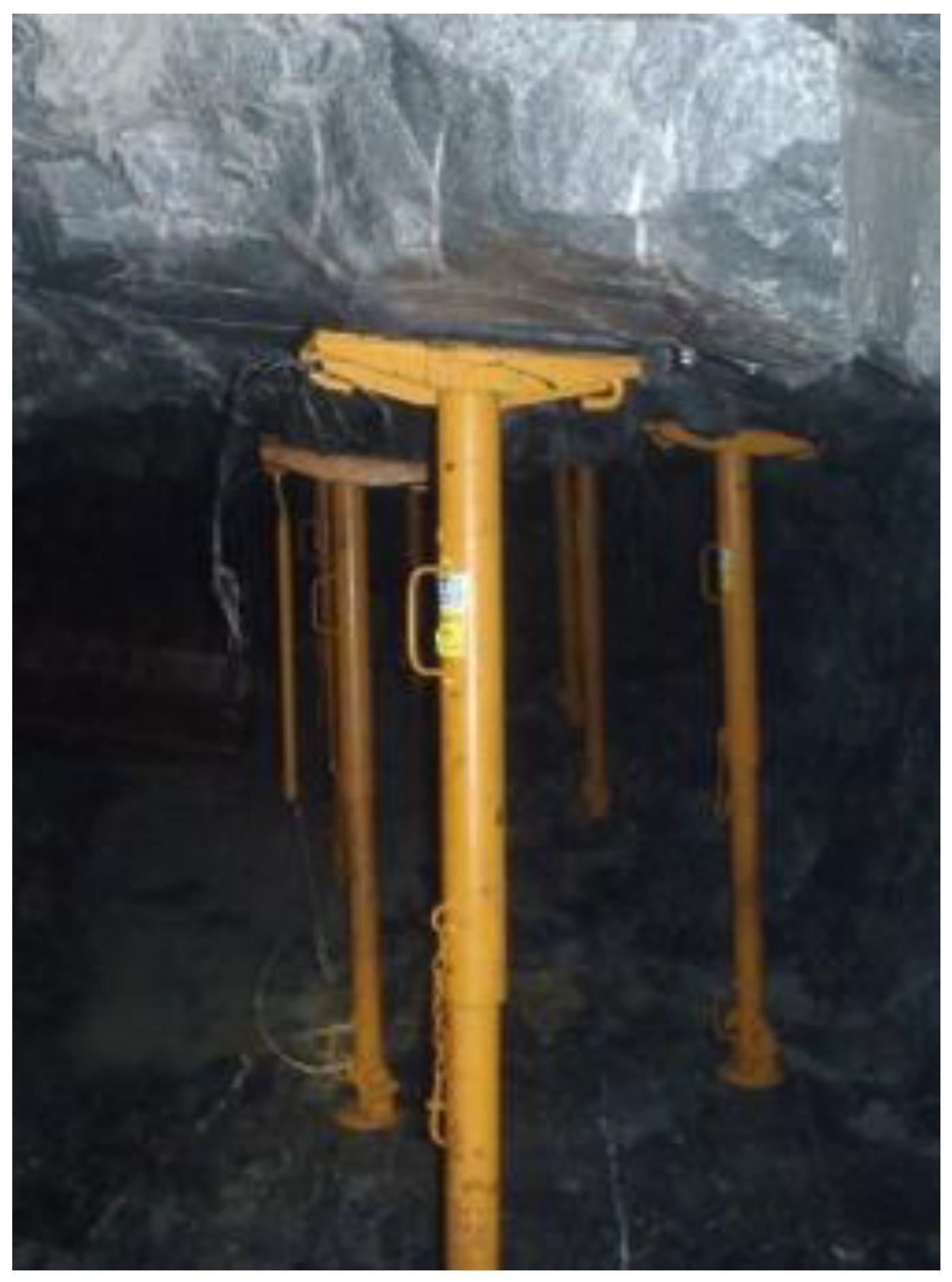
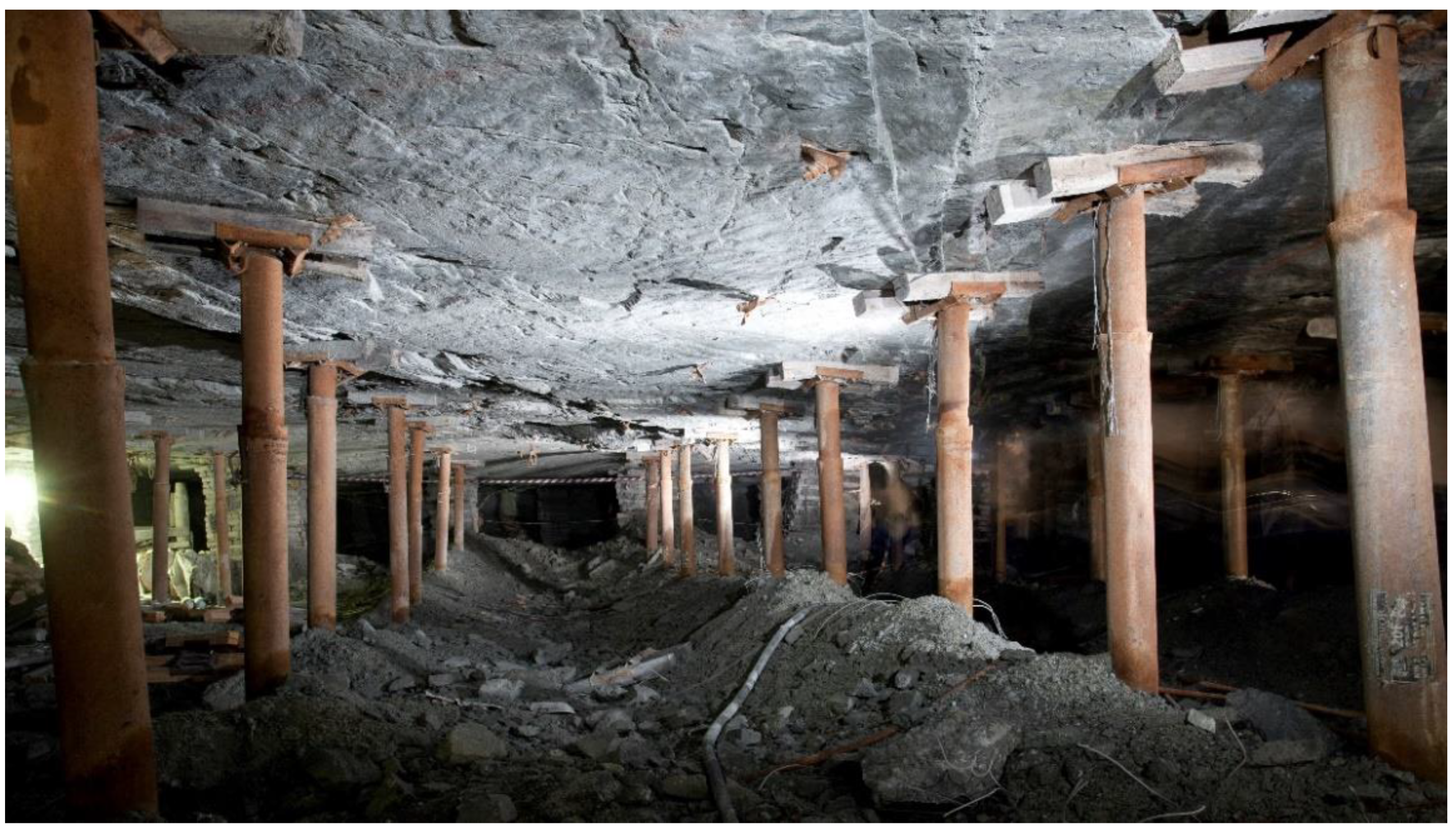
The Elbroc Omni prop and the Mine Support Products (MSP) Rocprops are shown in Figure 11. Both these props are manufactured in Johanessburg, South Africa, Elbroc and MSP are their respective manufacturers. The figure shows MSP props installed underground as permanent supports, with a high yield tonnage, pre-stressed using highly pressurized water and air. The Elbroc Omni prop has similar structural and performance qualities to the MSP prop. However, it contains a hydraulic pressure release valve which allows it to be reusable if no yielding has occurred. During static yielding, the props yield consistently at 20 tons, which is acceptable. A slight drop of 2 tons is periodically experienced during dynamic yielding [23]. The rock bolts should be installed in a row between props to decrease the spaces between supports. The yield behavior of the rock bolt and the props is the same.
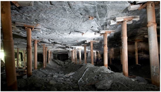
Figure 11.
Installed rock reinforcement elongates across stope [24].
2.4. Risk Evaluation of Rockfalls
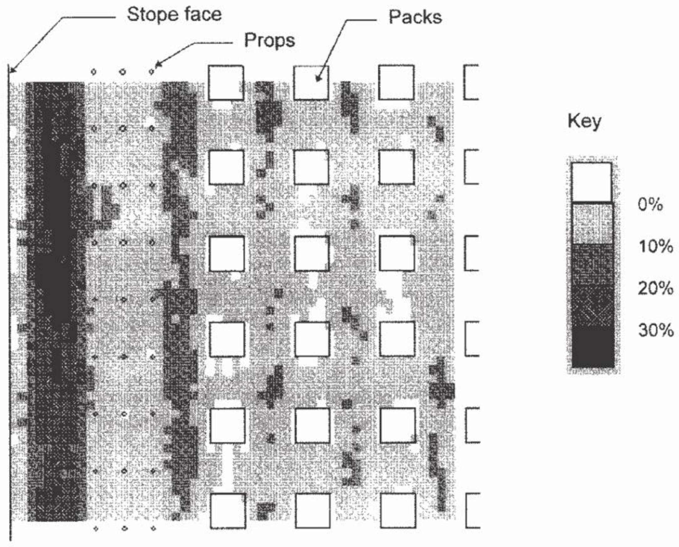
All the current rock reinforcements discussed in Section 2.2 and Section 2.3 must be installed evenly at equal distances. This proves to be a difficult task due to the unevenness of the terrain. Installed props and packs greatly hinder the working space for machinery and personnel and lower the chances of evacuating mine workers in case of danger. The authors in [25] provide a means of simulating the probability of a rockfall between supports and of the failure of the support props and packs when evenly spaced (Figure 12). The support consists of three rows of permanent high-yield-tonnage (20 tons) props adequately installed, spaced 1 m apart down the face in rows 2 m apart. The first row of props is 3 m from the face. The back-area support consists of mat packs spaced 3 m × 3 m apart. The supporting effect of the blasting face where retrieval of mineral ores takes place is clearly shown. The probability of failure in the blasting area is lower near the blasting face due to the solid rock that still needs to be blasted. The support props are 3 m from the blasting face; this results in a probability of failure of 40% between the blasting face and the line of support props. Between the rows of props, the probability is generally less than 10%. The probability of failure increases to values of between 10% and 20% between the packs. The effect of the 2 m gap between the last row of props and the packs results in a probability of failure between 10% and 20%. In Figure 12, a hanging wall is the roof above miners as the travel to a producing stope face.
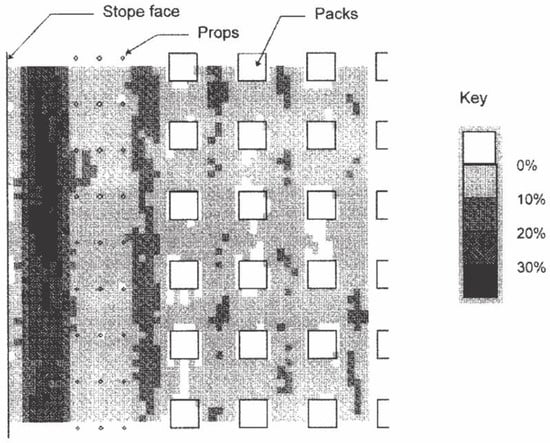
Figure 12.
Layout of props and packs supporting a hanging wall [25].
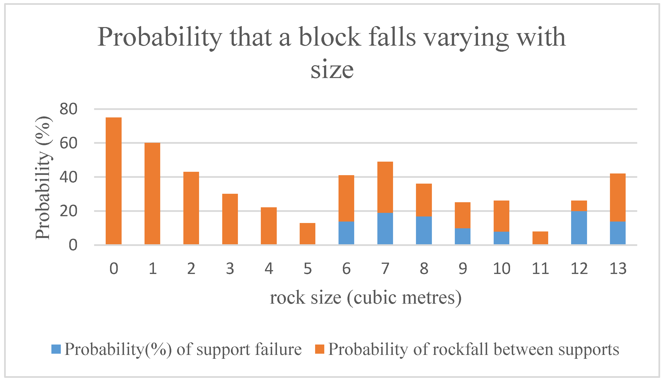
Figure 13 shows a bar graph of the probability of a rockfall between supports, showing the probability of a rockfall due to support failure against rock sizes. Rocprops are recommended to be installed 1.5 m apart in both width and breadth in a hanging wall. The height of the hanging wall varies by up to 6 m. We assumed a hanging wall height of 2.5 m in the following analysis.
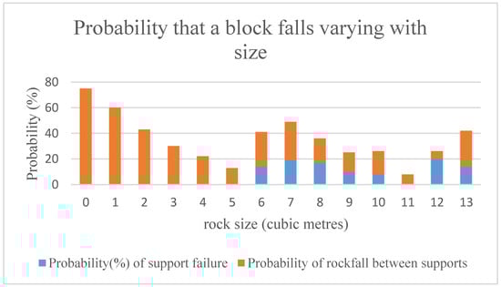
Figure 13.
Probability that a block falls against size [25].
The biggest possible rockfall between two adjacent supports would have a volume of 1.5 m × 1.5 m × 2.5 m = 5.63 m3 and has a probability of occurrence of 13%, as shown in Figure 13. By installing yield bolts halfway between the lines of Rocprops, the possible size of rockfalls between supports reduces to 0.75 m × 0.75 m × 2.5 m = 1.41 m3, with a probability of occurring of 60%. Furthermore, these rockfalls are less likely to be fatal [25].
Provided that rock reinforcement is installed adequately (situations (a) and (c) mentioned in Section 2.2), rock falls in hard rock mining can be eliminated. This is ensured by having a dedicated rock reinforcement inspector during installation and all mining activities. Figure 11 shows a whole channel with no support between supports, which creates a high-risk area for rockfalls. It is essential to have enough working space for miners, in order not to hinder productivity and to prevent congestion that may increase the probabilities of injury; thus, the area has no support. The risk of rockfalls between the props primarily inspires the continual development of roof bolts.
3. Methodology
Two research methodologies were applied in this study, namely: interviews and experimental methods. Providing a rationale for this work, Mine Support Products manufactured Split Set Stabilizer rock bolts but the sale and manufacture of these rock bolts was discontinued due to poor sales and the poor performance of the rock bolts in areas of high seismic activity. To improve the rock bolts’ performance, allowing re-entry to the reinforcement rock bolt market, the following questions were addressed to the interviewed rock engineers at the mining company working assisting with rock behavior information:
- (a)
- What is the static characteristic behavior of the rock?
- (b)
- What is the dynamic characteristic behavior of the rock?
- (c)
- What is the required load-bearing performance of the rock bolt?
- (d)
- What are the other environmental factors that may affect the bolt?
- (e)
- Which installation procedure is most suitable?
- (f)
- What is the working depth of the bolt?
In the experimental research, the design team met and discussed a new rock bolt design to meet the requirements arising in the interview responses. The various components of the new rock bolt were documented with their functions and were subsequently used to create a draft diagram using the computer-aided drafting software SolidWorks. An investigation into suitable materials available on the market and their properties was conducted. The additional components that were not standard were manufactured using CNC machining. The material specifications available on the market were the controlled variables; the experimental research contained multiple variables which were interchanged to examine different relationships between the dependent and independent variables.
The basic principle of the rock bolt design is a radially expanding hollow tube with a cone. In the laboratory, a hydraulic press was used to generate the pushing force to radially expand the tube. In situ, fall of ground and rock bursts generate the force to radially expand the tube. The force to radially expand the tube is applied to the surrounding rock structure to ensure its integrity. To examine this relationship, the following multiple variables were manipulated and controlled.
At the beginning, from the spreadsheet, the following properties of the tube were controlled: tube yield strength, width, length, tube internal diameter, and manufacturing process.
Cones with various outer diameter sizes were manufactured for yielding in the tube, it is the dependent variable. For a constant tube width (independent variable), all the various cones were used to yield the tube and obtain load bearing characteristics, the results were recorded.
Later, tube width was increased (dependent variable), the cone outer diameter was kept constant, and the results were recorded.
4. Preliminary Rock Bolt Design
The Mine Support Products (MSP) Company in Johannesburg is currently the leading supplier of rock reinforcement elongates to several hard rock mining companies in South Africa, currently the highest producer of gold in South Africa. Following the fluctuation in global steel prices, shortages, and the drop in the quality of steel produced, a client of MSP requested the research and development team to present rock reinforcement solutions that would continue to ensure optimal mine productivity. The required solution must mitigate the three conditions for a rockfall to occur, as discussed in Section 2.2, without hindering the already limited space available for mine workers and machinery.
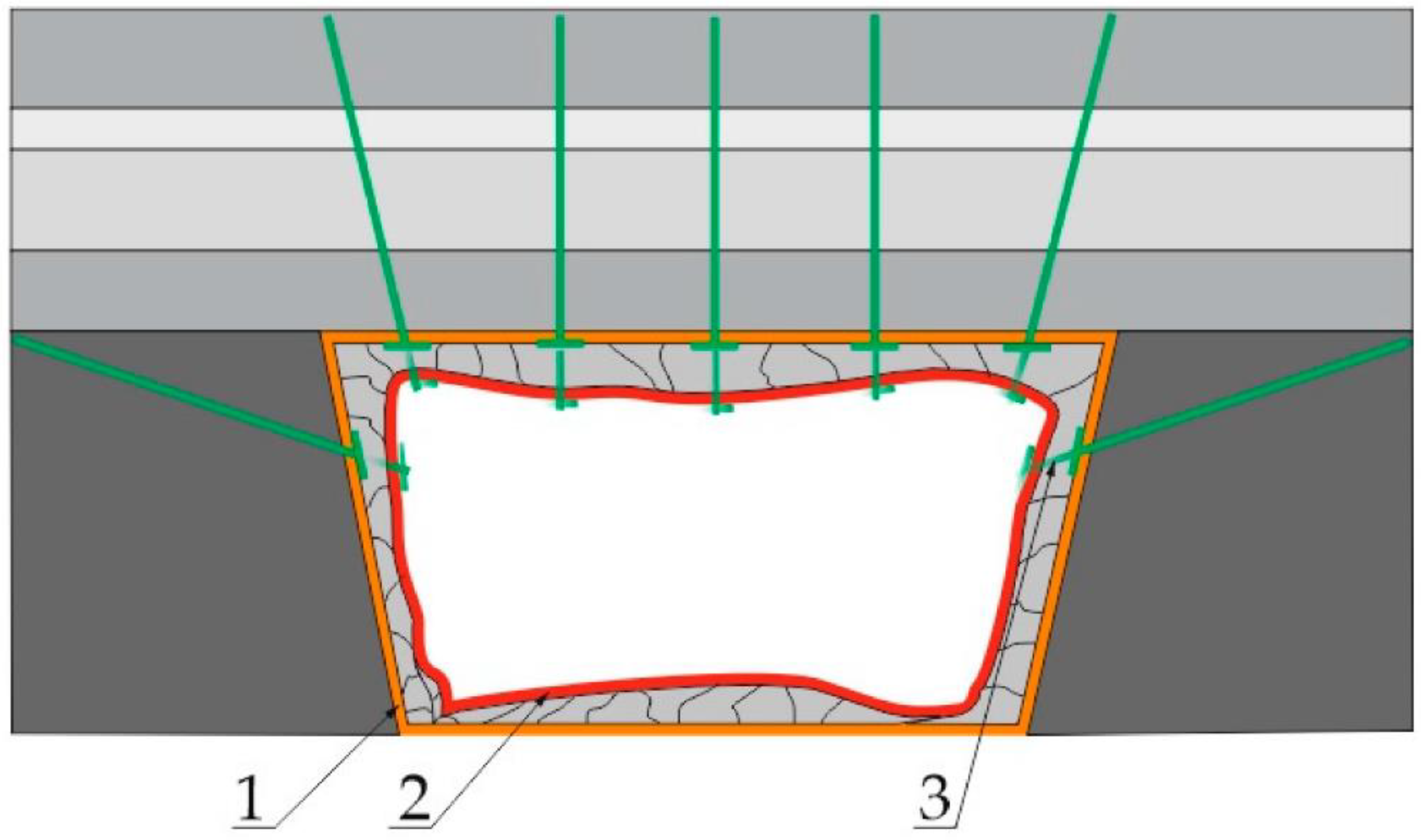
It became clear that the science of tunnel anchoring would provide the best-fit solution. However, the anchors would need to be re-designed to absorb the seismic activity occurring underground, with large rock deformations that require a yieldable support system to act as an energy-absorbing system [26]. Figure 14 shows a cross section of rock reinforcement using yield bolts at a stope. In the Figure 14, 1 represents the original room size, 2 is the shape of the room after the rock mass deformation and 3 indicates the support yield bolts.
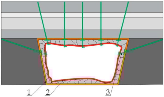
Figure 14.
Cross section of rock reinforcement using yield bolts [26].
The rock bolt is expected to yield at 200 kN, at a velocity of 3 m/s during dynamic events: this amounts to 60 kJ of energy. The Richter scale measures the amount of energy dissipated by an earthquake/the energy of a seismic wave. There are plenty of Richter scales placed all over the world in points of interest, especially near large fault lines to measure the intensity of earthquakes [27]. The energy measured depends on the distance between the instrument and the earthquake’s epicentre. One rock bolt should absorb 60 kJ of energy over 300 mm of yielding. Thus, 60 kJ of energy is required to radially expand each unit of length of the tube. Table 1 shows the amount of energy dissipated by an earthquake corresponding to a Richter scale measure. The scale has a maximum reading of 9.0, which amounts to 2.0 × 10¹⁵ kJ. South Africa is considered a stable region because it is situated far away from the fault lines of tectonic plates [28]. South Africa usually experiences earth tremors that are not categorized as earthquakes due to the energy they dissipate. However, in an underground mined-out area, an earth tremor can trigger disastrous rockfalls. Since every underground mine has a different mine layout and rock layout, varying distances to fault lines and no uniform support devices, it is difficult to simulate and anticipate the intensity of an earth tremor. The rock bolt absorbs 60 kJ of energy. More than 100,000 earthquakes of magnitude 1 and below occur yearly. These are minimal and are not felt by humans [29]. However, at great mine depths and in highly stressed rocks with fault lines underground, they can cause rockfalls. The rock bolt absorbs approximately the energy of a Richter 0.0 earthquake.

Table 1.
The amount of energy dissipated by an earthquake corresponding to the Richter scale measure [27].
From the product specification requirements produced by the client, we developed the physical and operational attributes of the required roof anchor. A detailed mathematical spreadsheet with the theoretical calculations of the expected yield tonnage of the rock bolt was created. The spreadsheet contained the different physical attributes of the rock bolt that were changed to produce the expected theoretical tonnage.
4.1. Concept
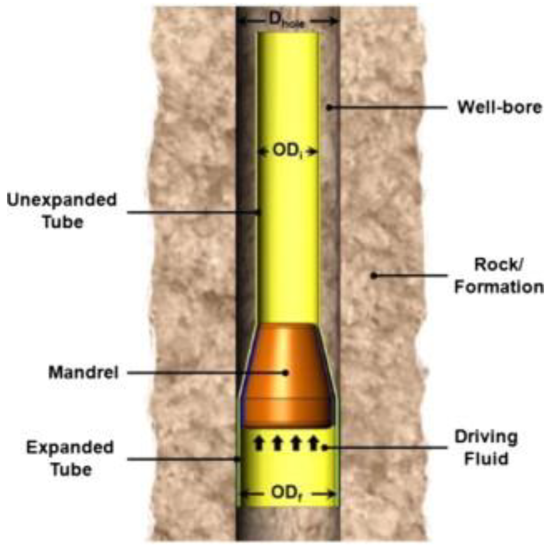
Research is currently being conducted on how to use the hollow expandable tube undergoing rapid radial expansion to ensure the integrity of ground excavations to retrieve oil. The aim is to replace the telescopic drilling method [30]. The telescopic method is susceptible to sporadic caving in of the side walls, which pollutes the oil being retrieved and hinders operations [30]. The idea is to allow for the controlled absorption of the energy of underground dynamic events. Figure 15 from [30] shows how a mandrel is pushed through a tube; the energy from a dynamic event is absorbed by the mandrel thus ensuring a rigid excavation by yielding the tube.

Figure 15.
Mandrel yielding a tube [30].
Theoretical Calculations
The excel spreadsheet calculations were conducted to find the theoretical results of the force on the cone when yielding the tube [30]. Table 2 shows a summary of the calculations, which are fully detailed in Appendix A.
Table 2.
Theoretical calculations of the force on the cone.
The physical design attributes that met the product requirement specification best were chosen and used for the development of the initial rock bolt design. The preliminary design of the rock bolt was drafted in SolidWorks (computer-aided drafting software) and is shown in Figure 16. The individual components of the design were then sent for machining and the rock bolt manufactured at MSP. The primary physical attributes that influenced the yield tonnage were the diameter of the tube, the type of tube (seamless or welded with a seam), the wall thickness of the tube, the size of the cone, and the correctness of the assumed static and dynamic friction coefficients.
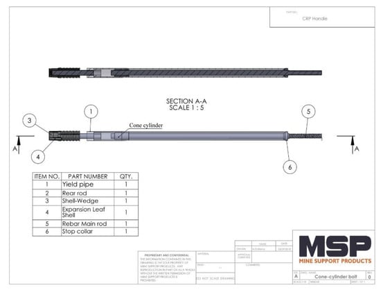
Figure 16.
Preliminary yield bolt design [31].
The properties of the preliminary rock bolt design are shown in Table 3.
Table 3.
Table of specifications for preliminary rock bolt design.
4.2. Testing of the Preliminary Rock Bolt Design
The equipment used for testing the preliminary rock bolt design consisted of 60-ton and 100-ton hydraulic presses that simulated the seismic activity that would occur underground. Both these machines are located at the MSP factory in Vereeniging, Gauteng, South Africa. The rock bolt was inserted into a steel frame which was mounted inside the hydraulic press. The bolt was fixed to the testing steel frame using a steel threaded rod, washers, and hexagonal nuts. The hydraulic press contained an extensometer and a load cell to record the force yielding the tube, the displacement, and the cone velocity [4]. The force diagram shows a cross section of the support provided by the rock bolt once installed; the downward movement force was produced by the hydraulic press. The top end of the bolt was fixed. The well bore is drilled to be slightly bigger than the tube outer diameter, and after pre-stressing the tube yields, creating an interference tolerance with the borehole. The rock bolt aims to counter the progression of fault lines that would otherwise cause rockfalls when stressed (Figure 17).
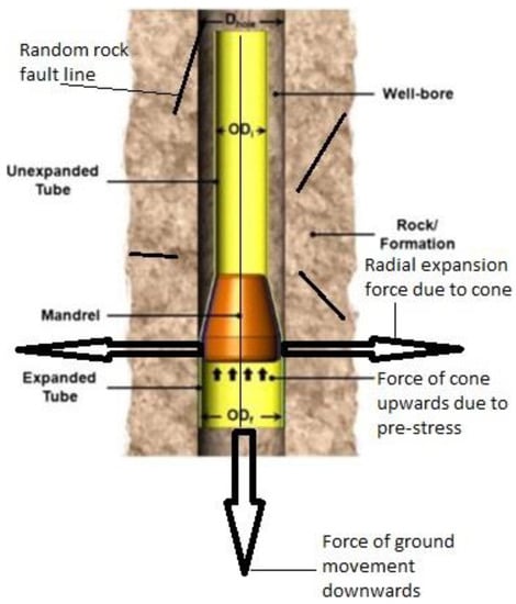
Figure 17.
Cross-sectional view of forces acting on the rock bolt [30].
These readings were plotted against each other on the computer software, as shown in Figure 18.
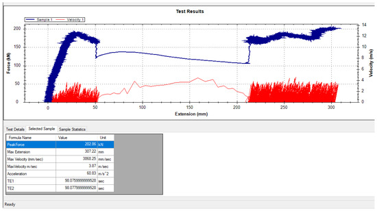
Figure 18.
Data acquisition software [19].
On 28 May 2020, the first batch of manufactured rock bolts was tested, pictured in Figure 19. Static and dynamic tests were conducted on the bolts. The static test simulated the gradual dropping of the supported roof, and the dynamic test simulated a sudden shock such as an earthquake/tremor.
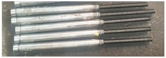
Figure 19.
Manufactured preliminary rock bolts [4].
For the dynamic test, simulating dynamic events, the hydraulic press cylinder pushed against the rock bolt at a velocity of 3 m/s. When testing began, the hydraulic cylinder started to pull a wire rope attached to the cone inside the tube and yielding started to occur. The force, extension, and velocity readings were plotted on a screen as the test proceeded, as shown in Figure 18. The tube yields 300 mm in length, which is the accepted standard for yielding rock reinforcement mechanisms in the mining industry.
Shortcomings of Preliminary Design
The preliminary rock bolt design was unsuccessful due to the following factors:
- (a)
- The yield tonnage during dynamic testing was below 18 tons, as in shown Figure 20. At 50 mm during testing, seismic activity was simulated, and this is where the low tonnage reading was noticed. The results show an unacceptably low yield tonnage and do not meet the performance requirement. The yield tonnage for static testing met the design performance of above 20 tons. The difference in yield tonnages was due to the different coefficients of friction between the two tests. The dynamic and static friction coefficients were 0.09 and 0.15, respectively [4]. The test results were combined in the analysis to view the overall behavior of the bolt, because it is not possible to predict which type of rockfall activity will occur.
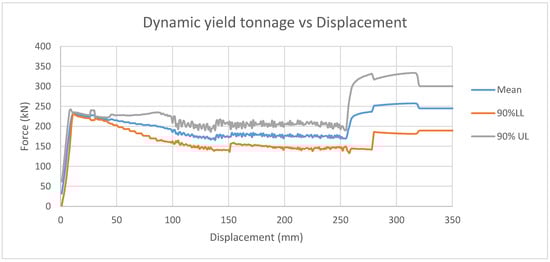 Figure 20. Preliminary yield bolt tonnage vs. displacement.
- (b)
- The manufacturing process of the preliminary rock bolt required welding of the rear stop collar and front plug. The welding restricted the expansion of the tube, which caused the tube to split open during testing [4], as shown in Figure 21.
 Figure 21. Splitting of preliminary rock bolt during testing.
- (c)
- It is costly, and small-diameter, thick-walled hollow tubes with no welding bead inside are not readily available for purchase. The welding bead increases the friction between the cone and the tube. However, because the weld bead was not uniform throughout the tube, the results were inconsistent.
- (d)
- One end of the tube must be flared in order to insert the cone. An entirely new set of tooling was required to flare it, and additional work was required to remove the weld bead. Inserting the cone with the weld bead caused the tube to buckle due to an unequal force distribution.
- (e)
- During testing, the rock bolt yielded at a slight angle, because the cone moves across the tube on the path of least resistance (away from the weld bead). The size and width of the weld bead were not uniform through the tube. At the end of testing, the threaded rod was no longer concentric with the circular opening of the rear end stop collar, which is evidence of the misalignment. The angle at which the cone caused misalignment was approximately 3°; the tensile forces acting on the bolt reduced the angle of misalignment.
- (f)
- Seamless tubes of small outer diameter (32 mm) were manufactured by drilling the internal diameter from a solid cylinder to the desired diameter. This operation makes the tube very expensive. The tubes are manufactured for hydraulic purposes and thus had low yield strength. Increasing the cone size to increase the yield strength resulted in premature bending of the tube.
In Figure 20, the mean yield tonnage against displacement graph is shown for the preliminary rock bolt design. A 90% standard deviation for the upper and lower limit is also shown. The standard deviations are shown to predict the best- and worst-case scenarios of the performance of the rock bolt following the quality tolerance of the materials used. The lower limit standard deviation shows that the preliminary rock bolt yield tonnage did not meet the requirements. After the dynamic event, the cone and tube were misaligned, resulting in a massive increase in the force as the tube was yielding nonlinearly [4]. These high forces may cause the tube to fracture, resulting in a failed support system.
5. Improved Design of Rock Bolt
To mitigate the risk of rockfalls occurring in mining excavations, an adequate support system is required. The results from the preliminary investigation contributed to the redesign of the yield bolt, which aimed to address the failures of the preliminary design. The objective of the improved rock bolt design was to minimize the space between rock reinforcements with minimal intrusion into the working space of miners and underground equipment. The yield bolt is fixed within the roof of the stope and absorbs the energy of a rockfall. The absorption is due to a cone radially expanding a tube due to the force produced by the rockfall. Figure 22 shows the improved rock bolt design. The main difference between the preliminary model and the improved model was the absence of internal welding in the improved model. Welding of the rear stop collar and front plug restricted the expansion of the tube, causing splitting of the tube during testing. The improved model does not require welding and is manufactured as a single cast component.
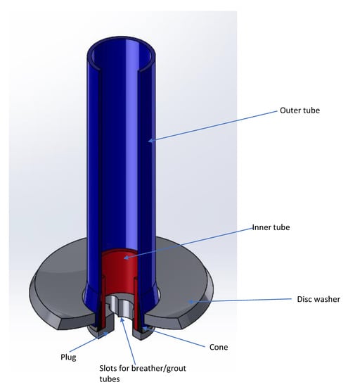
Figure 22.
Improved rock bolt design.
5.1. Design Details
The initial product requirement specifications for the preliminary design were used. The shortcomings of the preliminary rock bolt design ensured that an adaptive design would be used for optimization. Three major improvements were made to tackle the shortcomings of the preliminary rock bolt. Table 3 shows the dimensions of the preliminary rock bolt and Table 4 shows the dimensions of the improved model, with the following parameters:
Table 4.
Yield bolt components.
- (a)
- Increased tube outer diameter and cone;
- (b)
- Use of seamless tubes;
- (c)
- Insertion of an inner guide tube.
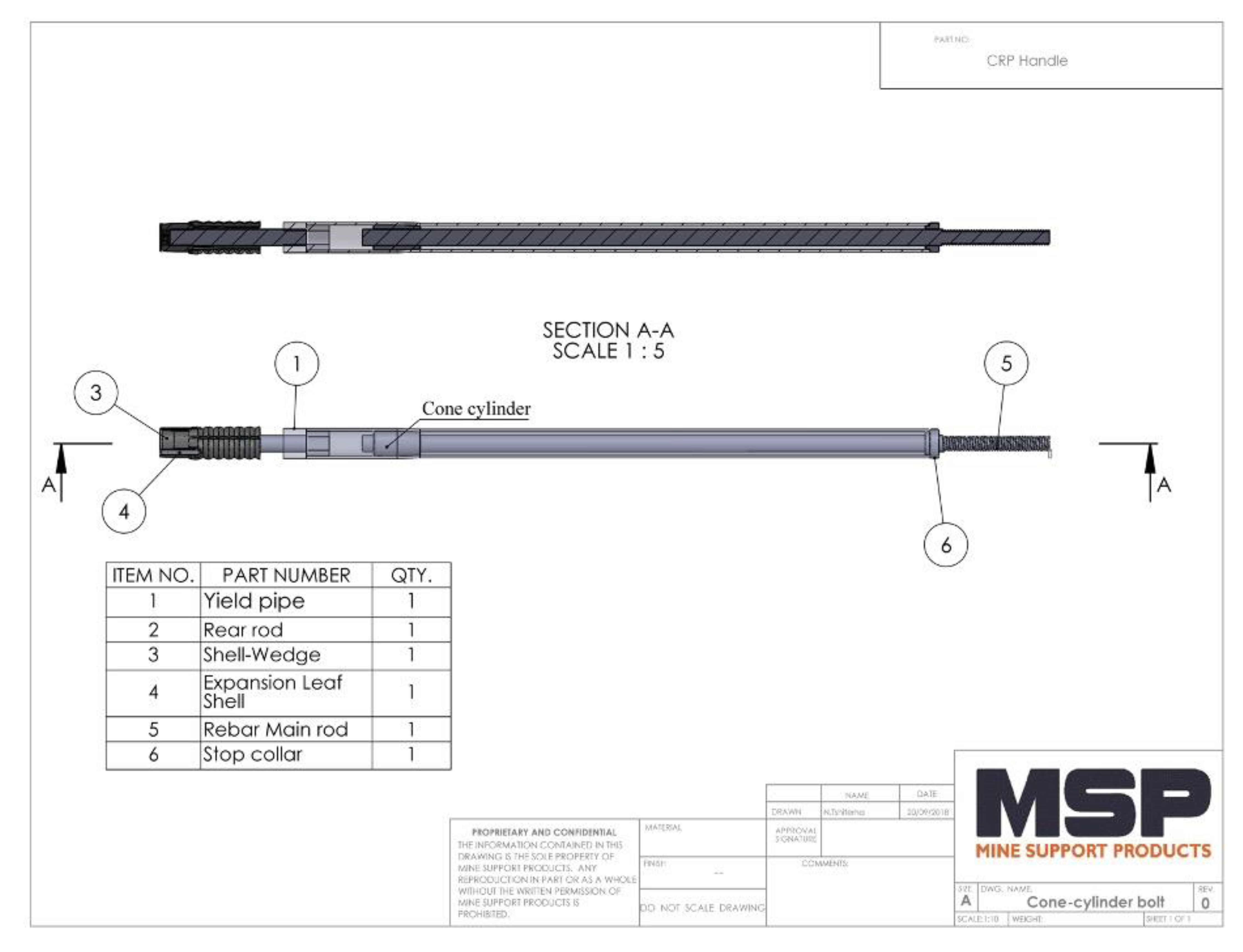
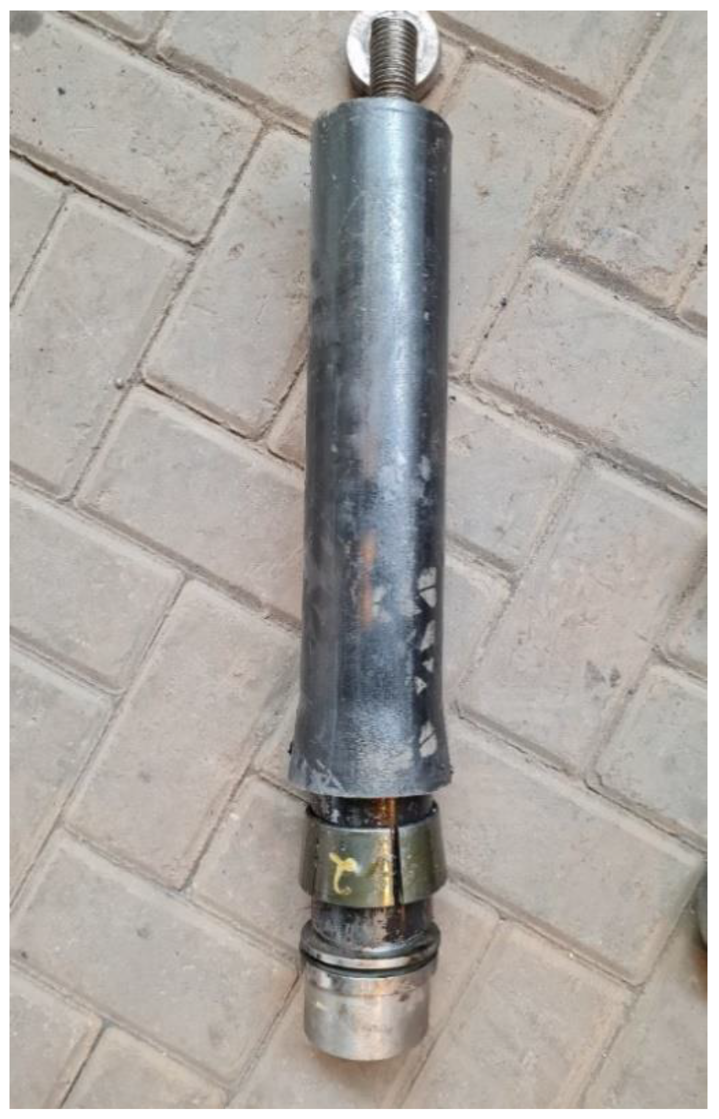
Figure 23 shows the assembly of the yield bolt before testing, and Table 4 provides details of the yield bolt components.
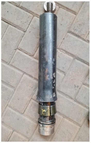
Figure 23.
Assembled improved rock bolt.
5.2. The Improved Model
To assemble the rock bolt, the inner guide tube is inserted into the cone. The plug is threaded onto a rod and moved in through the inner guide tube. Lastly, the outer tube is placed over the cone where it is flared, to make the complete assembly.
5.3. Experimental Set-Up and Equipment for Testing of Improved Design
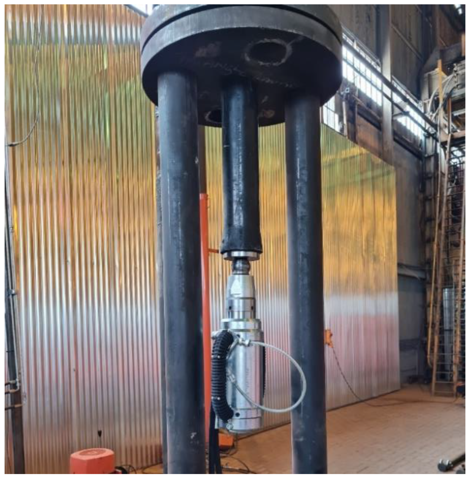
The testing procedure and equipment used were the same as those for the preliminary rock bolt design. However, in the improved model test, the bolt was fixed to the testing frame using steel anchor wire rope, washers, and ferrules. In the preparation for the test, the yield bolt was pre-stressed to 20 tons instead of being firmly fixed by hexagonal nuts. A hand pump and a stainless-steel ball terminal end were connected to the rock bolt cable anchor at both ends. Once fixed, the pump starts pushing against the ball terminal, eventually pushing in the cone to pre-stress the rock bolt assembly to 20 tons. This ensures that the bolt is firmly fixed into the hanging wall and exerts an upward force on it. The hand pump with the rock bolt is shown in Figure 24, which shows the experimental set-up for dynamic testing.
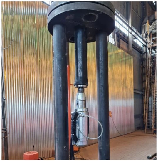
Figure 24.
Experimental set-up.
6. Results
6.1. Test Results
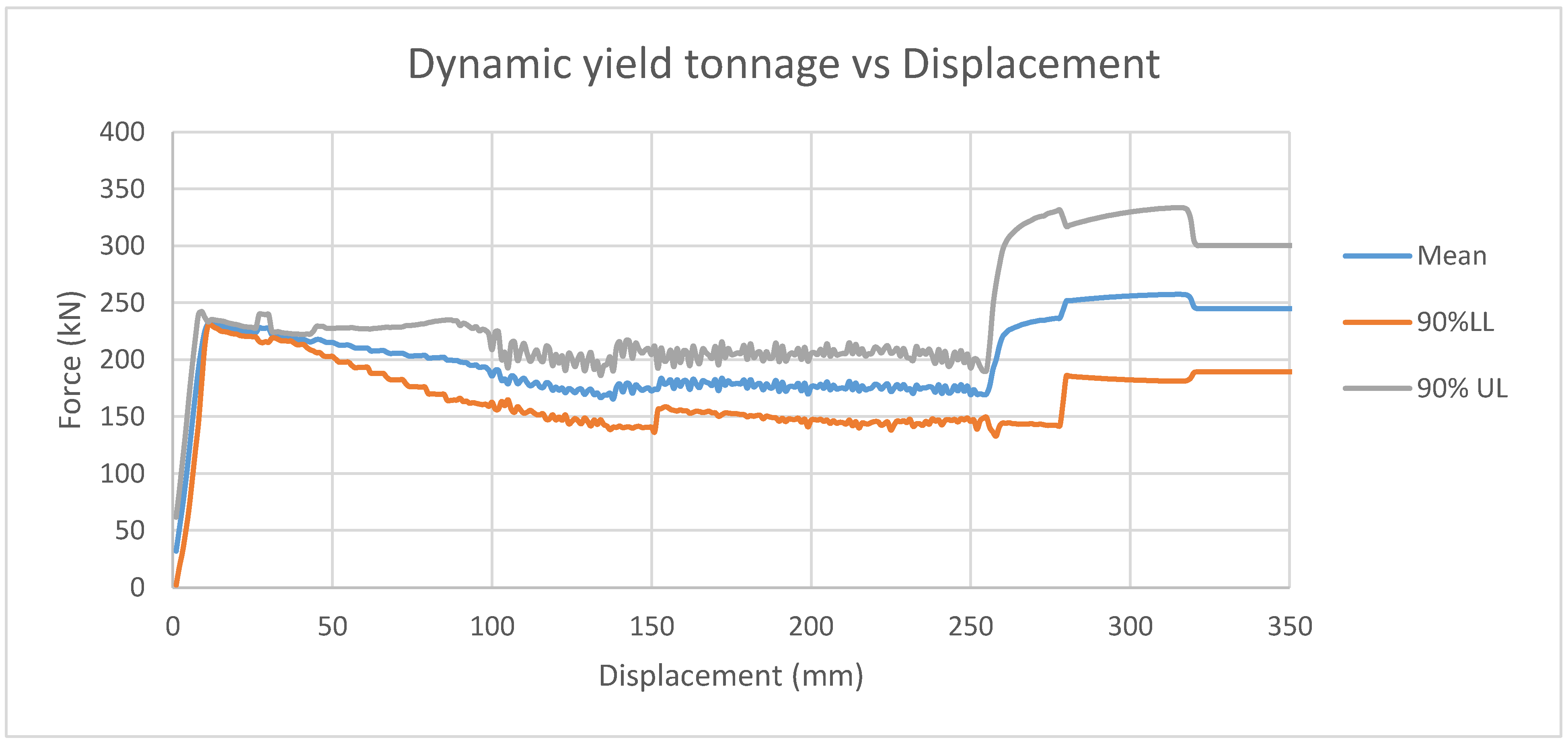
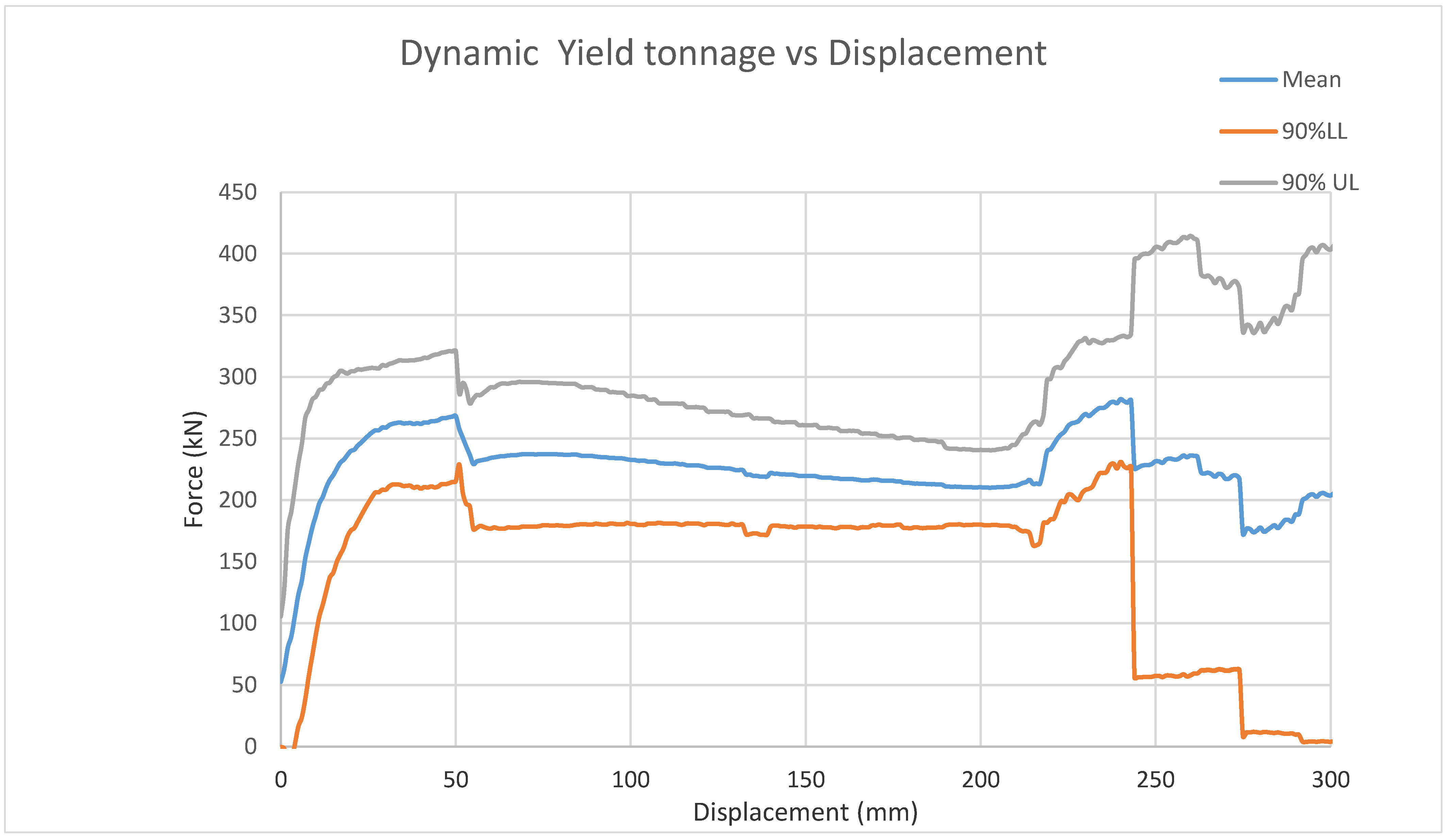
Figure 25 shows the mean yield tonnage against the cone’s displacement during dynamic testing of the improved rock bolt design. A 90% standard deviation for the upper and lower limit is also shown. The standard deviations are shown to predict the best- and worst-case scenarios of the performance of the rock bolt following the quality tolerance of the materials used. The lower limit standard deviation shows an average of 18 tons, which is an acceptable yield tonnage in the event of a poor-quality batch of materials.
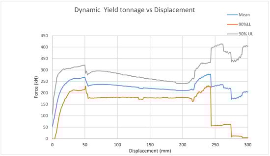
Figure 25.
Yield tonnage vs. displacement.
6.2. Discussion
The accepted standard for the yield tonnage of rock reinforcement devices in medium-risk areas is 20 tons. This is the consensus in the mining sector [19]. For mining activities in areas of high risk, the accepted yield tonnage is 35 tons. Figure 24 shows that the mean yield tonnage of the improved bolt was above 20 tons. Even after the dynamic event simulation at 50 mm, it successfully remained above 20 tons. Maintaining strict quality tolerances for the rock bolt allows for successful absorption of 60 kJ of energy, as required. The working principle of the improved yield bolt is based on radially expanding a hollow tube to absorb the energy of seismic activity [4]. The investigation showed that after a dynamic event, tubes failed to maintain their yield tonnage. However, the preliminary design of the yield bolt contained welded components. The effect of welding on the yielding tube decreased the yield strength, the tensile strength, and the impact toughness [32], resulting in a lower tonnage when testing. The high current and voltage during welding allowed defects to be formed in the microstructure of the steel [32]. Welding at lower currents and voltages is impossible because low welding penetration results in a weak joint. The design of the improved yield bolt does not require any welding during manufacture, as shown in Figure 23. This is also advantageous for transportation, as components can be transported separately and assembled underground; thus, many yield bolts can be transported per shift.
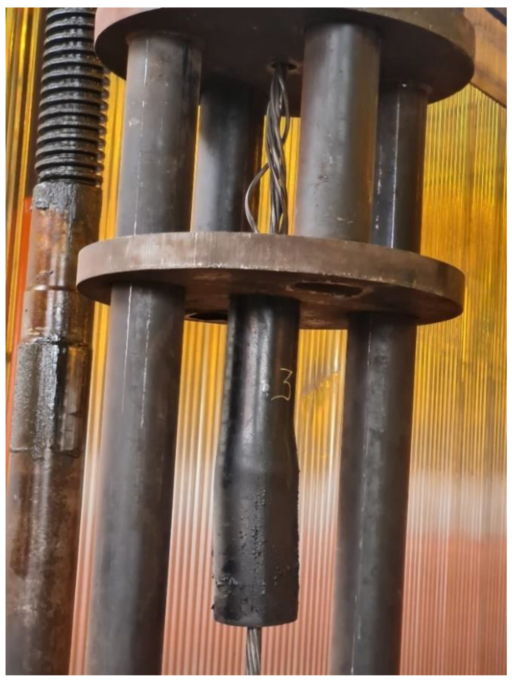
A total of eight tests were conducted; only the tests that significantly changed the behavior in the test results are discussed. Tests 1 and 3 failed in two unexpected ways that greatly influenced the improvement of the rock bolt; the other six tests were successful. During testing of the improved design (test 1), because of the high yield tonnage, the plug used to secure the guide inner tube sheared off, as shown in Figure 26. The effects of this failure are visible in Figure 20, where at 250 mm, the load drops to zero. In the event of this failure underground, the supported roof would have collapsed. The plug was redesigned to support the load adequately in the optimized design.

Figure 26.
Yield bolt test 1 mode of failure.
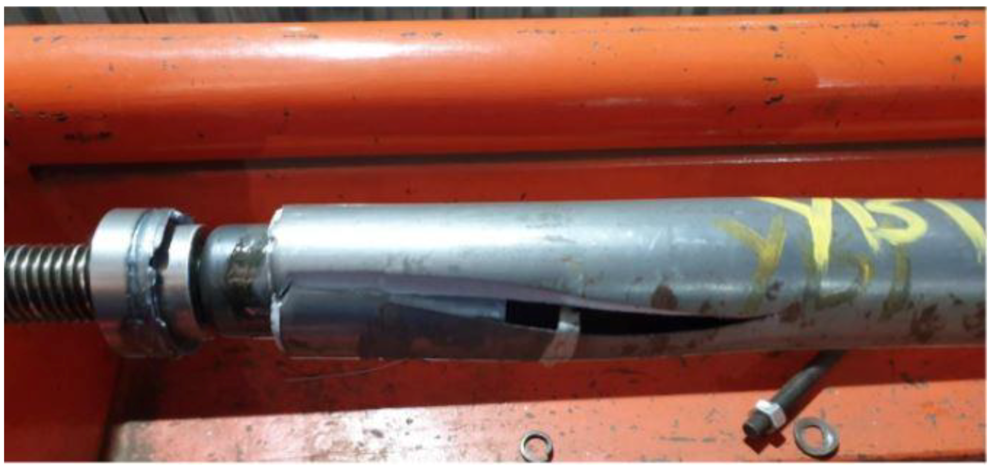
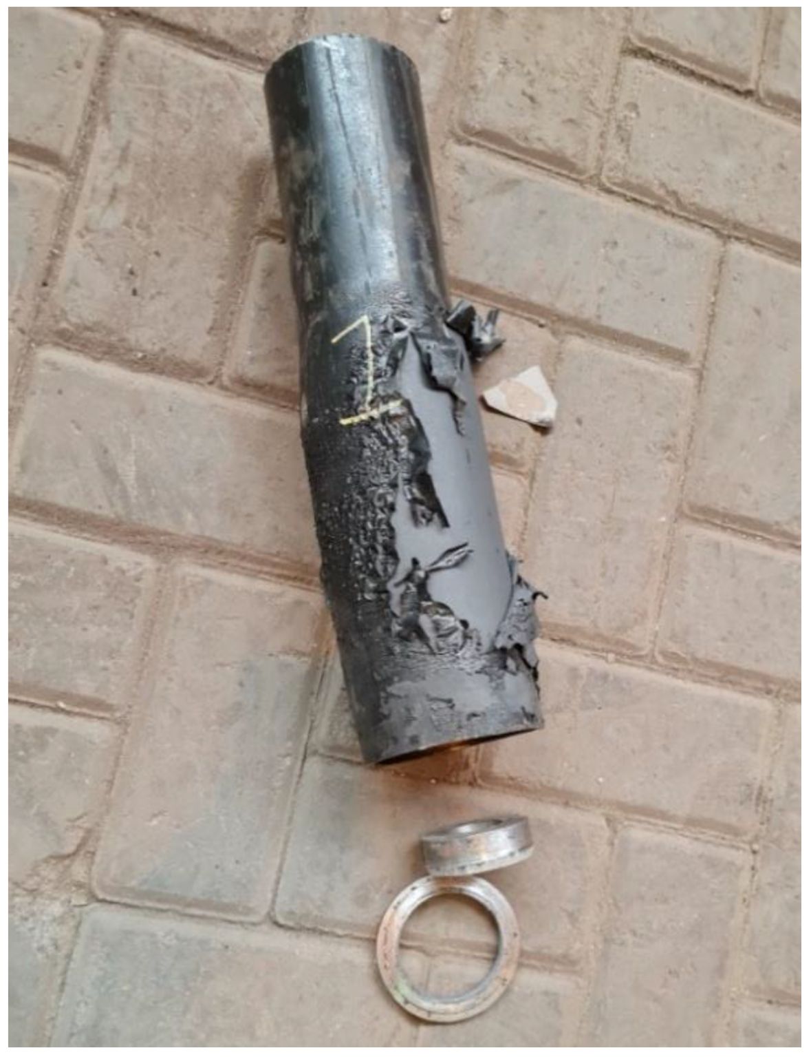
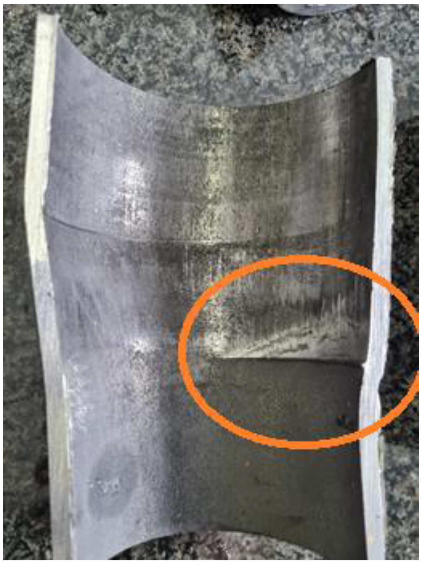
Towards the end of test 3, the yield tonnage started to increase exponentially. This was caused by the inner tube digging into the outer tube, thus restricting the cone from progressing. The dynamic event shifts and misaligns the inner tube causing the exponential increase in forces. Figure 27 shows a cross-sectional cut through the tube, showing evidence of the inner tube digging into the outer tube.
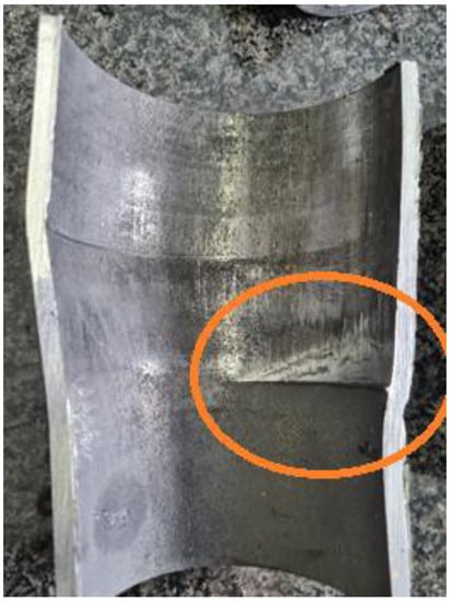
Figure 27.
Evidence of inner tube digging into the outer tube.
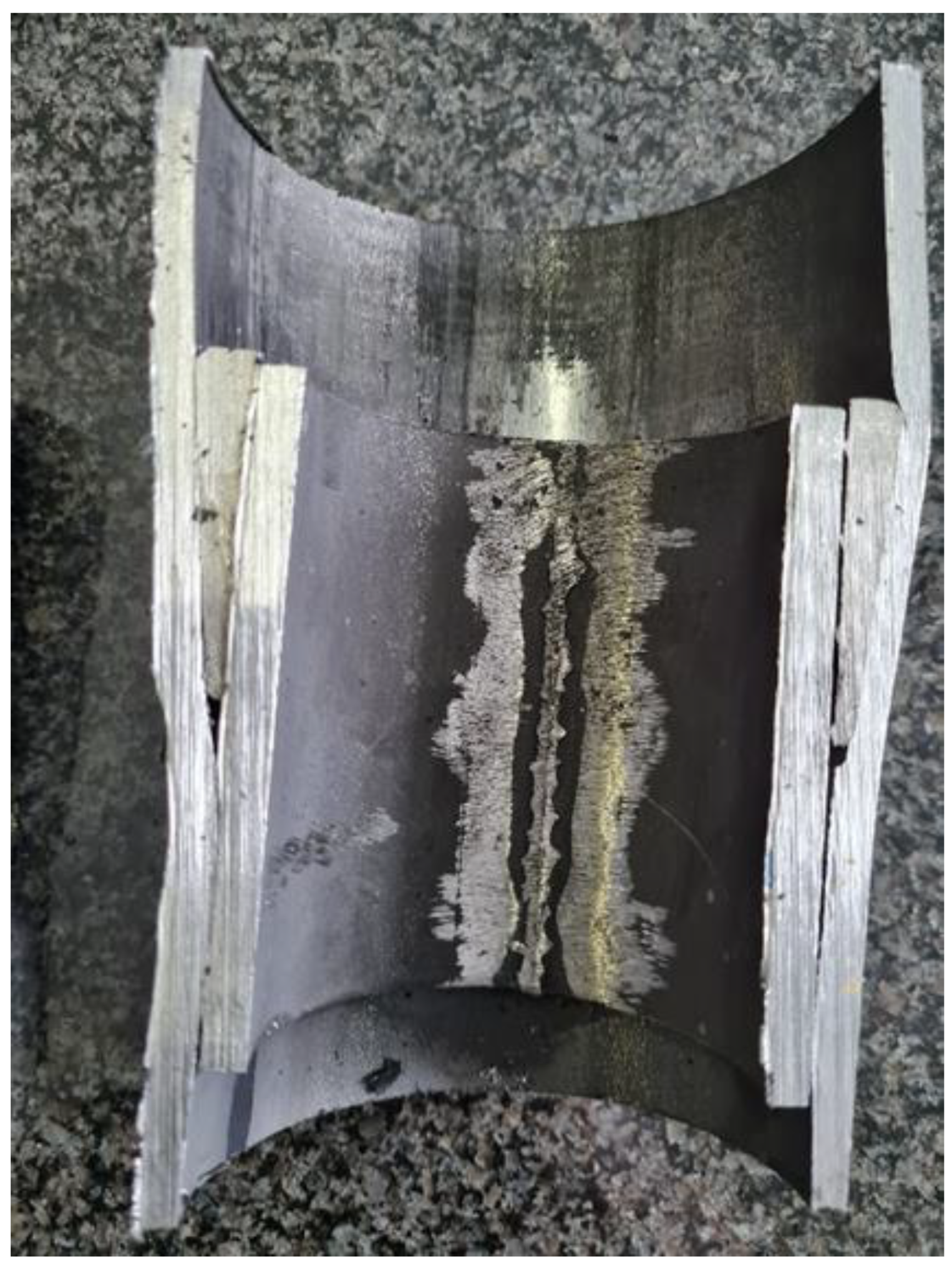
Figure 28 shows a cross-sectional view of the cone with the inner tube and outer tube, providing evidence of the misaligned cone. To prevent misalignments of the inner tube during operation underground, the length of the inner guide tube was increased in the improved design. Furthermore, due to the failure mode of test 3, the wire rope used to pre-stress the yield bolt underground began to fail, as shown in Figure 29.

Figure 28.
Misalignment of cone.

Figure 29.
Wire rope failure during testing.
6.3. Cone Element
The angle of the cone was 6.67°. The angle has a major role in the yielding of the tube. Higher angles provide higher forces but threaten the structural integrity of the tube. The cone had a thickness of 5mm and hardness of 43 HRC after heat treatment; this allowed the cone to prevent the huge compressive forces from yielding the tube. The length of the cone was 43 mm, providing a large surface area of contact with the tube. In a given rock mass, each tube will yield at 20 tons; the larger the rock mass the faster the tube will yield and the steeper the gradient of the yield force. The bolts are intended to be installed at equal distances of 1.5 m from each other for optimal performance. Installing too few bolts within a rock mass will cause the bolts to yield quickly to 300 mm, causing failure and resulting in less evacuation time for workers.
During installation, the hand pump pushes the stop collar inwards. This action pushes in the cone resulting in a positive force reinforcing the roof. This pre-stress force allows the rock bolt to be firmly fixed. The wire rope inclusion shown in the diagram complicates the active working components that need to be present in the borehole (Figure 17).
7. Conclusions
The improved yield rock bolt addressed the shortcomings of the preliminary yield rock bolt. The yield tonnage was similar to that of Rocprops, ensuring no premature rock reinforcement failure of any device in the event of a rockfall. It is also evident that the yield tonnage remained sufficient during dynamic events. The improved yield rock bolt must be assembled underground; therefore, no manufacturing defects are expected, and only a strict quality check of machined components is required. MSP has a dedicated quality inspector for all internal and external products received or produced. Precision machining techniques are readily available to ensure strict quality adherence. Precision quality jigs can be manufactured to support quality checks manually once production begins.
The improved design ensured that the yielding of the tube was linear by using an inner guide tube, thus preventing any other component failures of the rock bolt in operation underground. The tubes used to manufacture the improved rock bolt with consistent performance are readily available on the market. The tooling required for manufacturing the rock bolt is already set up at MSP, but personnel would require training to meet the quality checks for manufacturing. The working personnel are already well trained for the machine operations. Arrangements are being made to have the improved rock bolt introduced underground for testing and observation in the working environment. This will form a part of another paper. Following this, the system will be simulated in suitable computational software, such as Ansys, to provide predictions of the dynamic behavior of the rock bolt beyond the window of normal operation. This will form the scope of yet another paper. Some contributions of the present paper to the field are: (1) designing a rock bolt with no welding requirement; (2) testing both the static and dynamic behavior of rock bolts and achieving linearity in the yielding of the tube; (3) designing the system to maximize the spacing underground to limit interference with working space for personnel and equipment. Furthermore, the improved rock bolt is designed to be easily assembled underground. These results will inform designers, manufacturers, and installers.
Author Contributions
Conceptualization, N.T.; methodology N.T.; software, N.T.; validation, D.V.V.K.; formal analysis, D.V.V.K.; investigation, N.T.; resources, N.T.; data curation, N.T.; writing—original draft preparation, N.T.; writing—review and editing, D.V.V.K.; visualization, N.T.; supervision, D.V.V.K.; project administration, N.T.; funding acquisition, N.T. All authors have read and agreed to the published version of the manuscript.
Funding
This research received no external funding and the APC was funded by University of Johannesburg.
Data Availability Statement
The research data results may be retrieved form Mine Support Products, Johannesburg, South Africa.
Acknowledgments
We are grateful to Mine Support Products (MSP) Company for granting us access to data and allowing use of their testing equipment and work with all their staff.
Conflicts of Interest
The authors declare no conflict of interest.
Appendix A
Theoretical Calculations
Cone angle in degrees [φ]:
Lateral area of cone [Al]:
Surface area of cone:
Stress on cone:
Force on cone:
Static frictional force component:
Dynamic frictional force component:
Yielding force for static:
Yielding force for dynamic:
The expected static and dynamic yield forces are 22.13 and 14.95 tons, respectively.
References
- The Federation of a Suitable Environment. The Impact of Mining on the South African Economy and Living Standards. 2018. Available online: http://fse.org.za/index.php/item/593-the-impact-of-mining-on-the-south-african-economy-and-living-standards (accessed on 15 February 2021).
- NS Energy Business. Mponeng Gold Mine. 2021. Available online: https://www.nsenergybusiness.com/projects/mponeng-gold-mine/#:~:text=The%20Mponeng%20gold%20mine%20located,AngloGold%20Ashanti%20in%20South%20Africa (accessed on 18 February 2021).
- Sharma, P. Enviromental and Engineering Geophyisics; Cambridge Unversity Press: Cambridge, UK, 1997. [Google Scholar]
- Tshitema, N.; Kallon, D.V.V.; Lasiende, O. Investigation of radial expansion of hollow tubular devices for support of underground mining excavations. In Proceedings of the International Conference on Industrial Engineering and Operations Management, Dubai, United Arab Emirates, 10–12 March 2020; Volume 59, pp. 381–387. [Google Scholar]
- Plouffe, M.; Anderson, T.; Judge, K. Rock Bolts under Dynamic Conditions at Canmet-MMMSL; Natural Resources Canada: Gatineau, QC, Canada, 2007. [Google Scholar]
- Anglo American. 2021. Available online: https://www.angloamerican.com/futuresmart/stories/our-industry/mining-explained/digging-deeper-mining-methods-explained (accessed on 15 February 2021).
- Stacey, T.R.; Gumede, H. Evaluation of risk of rock fall accidents in gold mine stopes based on measured joint data. J. S. Afr. Inst. Min. Metall. 2007, 3, 346. [Google Scholar]
- Mehmood, A. Chinese coal mines—The industrial death trap. Pak. Med. Assoc. 2009, 59, 649–650. [Google Scholar]
- Dozolme, P. The Balance Small Business. 2019. Available online: https://www.thebalancesmb.com/most-common-accidents-occurring-in-the-mining-industry-2367335#:~:text=Most%20of%20the%20deaths%20today,35%25%20of%20the%20world’s%20coal (accessed on 20 March 2021).
- Kissel, F.; Tien, J.; Thimons, E. Methods for Controlling Explosion Risk at Coal Mine Working Faces. In Proceedings of the International Conference of Safety in Mines Research Institutes, Beijing, China, 28–29 September 2007; National Center for International Exchange & Cooperation on Work Safety: Beijing, China. Available online: https://www.cdc.gov/niosh/mining/works/coversheet1682.html (accessed on 20 August 2021).
- Department of Mineral Resources. Occupational Health and Safety Report: October 2017; Department of Mineral Resources: Pretoria, South Africa, 2017.
- Harmin, H. Guide to Underground Mining Methods and Applications; Atlas Copco: Stockholm, Sweden, 1997. [Google Scholar]
- Encyclopaedia Britannica. 2021. Available online: https://www.britannica.com/science/Geophone (accessed on 10 March 2021).
- New Concept Mining. Fall of Ground Light; New Concept Mining: Johannesburg, South Africa, 2019. [Google Scholar]
- Stillborg, B. Proffesional Users Handbook for Rock Bolting, 2nd ed.; Trans Tech Publications: Clausthal-Zellerfeld, Germany, 1994. [Google Scholar]
- Kim, H.; Rehman, H.; Ali, W.; Naji, A.M.; Kim, J.; Yoo, H. Classification of Factors Affecting the Performance of Fully Grouted Rock Bolts with Empirical Classification Systems. Appl. Sci. 2019, 9, 4781. [Google Scholar] [CrossRef] [Green Version]
- New Concept Mining. MP1 Rocbolt; New Concept Mining: Johannesburg, South Africa, 2019. [Google Scholar]
- Nissen, C.; (Technical Manager-Mine Support Products, Vereeniging, South Africa). Unpublished work. 2019.
- Nissen, C. Mine Support Products. 2019. Available online: https://www.msp.co.za (accessed on 20 May 2020).
- Bedrock Mining. Bedrock Mining Timber Production; TWK Agri: Nelspruit, South Africa, 2019; Available online: https://www.twkagri.com/ (accessed on 15 May 2021).
- Timrite. Temprite Cam Prop.; Timrite: Johannesburg, South Africa, 2016. [Google Scholar]
- Smith, R.; (Test Engineer-Mine Support Products, Vereeniging, South Africa). Unpublished work. 2019.
- Nissen, C. SHEQ.RA095; Mine Support Products: Johannesburg, South Africa, 2015. [Google Scholar]
- Mine Support Products. Installed Rocprops; Mine Support Products: Johannesburg, South Africa, 2018. [Google Scholar]
- Esterhuizen, G.S.; Streuders, S.B. Rockfall Hazard Evaluation Using Probabilistic Keyblock Analysis. J. S. Afr. Inst. Min. Metall. 1998, 98, 59–64. [Google Scholar]
- Skrzypkowski, K.; Korzeniowski, W.; Zagórski, K.; Zagórska, A. Modified Rock Bolt Support for Mining Method with Controlled Roof Bending. Energies 2020, 13, 1868. [Google Scholar] [CrossRef] [Green Version]
- Volcano Discovery. 2005. Available online: https://www.volcanodiscovery.com/about/volcanodiscovery.html (accessed on 9 August 2021).
- Brandt, M. Seismic Hazard in South Africa. Counc. Geosci. 2011, 61, 1–22. [Google Scholar]
- Rafferty, J. Britannica. 2020. Available online: https://www.britannica.com/science/Richter-scale (accessed on 22 October 2021).
- Al-Abri, O.S.; Pervez, T. Structural behaviour of solid expandable tubular undergoes radial expansion process. Int. J. Solids Struct. 2013, 50, 2980–2994. [Google Scholar] [CrossRef] [Green Version]
- Tshitema, N. Yielding Bolt for Roof Support. In Underground Excavations; Timrite: Johannesburg, South Africa, 2018. [Google Scholar]
- Talabi, S.; Owolabi, O.; Adebisi, J.; Yahaya, T. Effect of welding on mechanical properties of low carbon steel welded joint. Adv. Prod. Eng. Manag. 2014, 9, 181–186. [Google Scholar] [CrossRef] [Green Version]


Publisher’s Note: MDPI stays neutral with regard to jurisdictional claims in published maps and institutional affiliations. |
© 2021 by the authors. Licensee MDPI, Basel, Switzerland. This article is an open access article distributed under the terms and conditions of the Creative Commons Attribution (CC BY) license (https://creativecommons.org/licenses/by/4.0/).