
Potential of Salt Caverns for Hydrogen Storage in Southern Ontario, Canada


1
State Key Laboratory of Petroleum Resources and Prospecting, China University of Petroleum-Beijing, Beijing, 102249, China
2
College of Geosciences, China University of Petroleum-Beijing, Beijing, 102249, China
3
Department of Civil and Enviromental Engineering, University of Waterloo, Waterloo, ON N2L 3G1, Canada
4
Geological Survey of Canada, Calgary, AB T2L 2A7, Canada
*
Author to whom correspondence should be addressed.
Mining 2023, 3(3), 399-408; https://doi.org/10.3390/mining3030024
Submission received: 7 June 2023
/
Revised: 6 July 2023
/
Accepted: 7 July 2023
/
Published: 9 July 2023
Abstract
:Salt caverns produced by solution mining in Southern Ontario provide ideal spaces for gas storage due to their low permeability. Underground hydrogen storage (UHS) is an important part of the future renewable energy market in Ontario in order to achieve global carbon neutrality and to fill the gap left by retiring nuclear power plants. However, large-scale hydrogen storage is still restricted by limited storage space on the ground’s surface. In this study, hydrogen’s physical and chemical properties are first introduced and characterized by low molecular weight, high diffusivity, low solubility, and low density. Then, the geological conditions of the underground reservoirs are analyzed, especially salt caverns. Salt caverns, with their inert cavity environments and stable physical properties, offer the most promising options for future hydrogen storage. The scales, heights, and thicknesses of the roof and floor salt layers and the internal temperatures and pressures conditions of salt caverns can affect stabilities and storage capacities. Finally, several potential problems that may affect the safe storage of hydrogen in salt caverns are discussed. Through the comprehensive analysis of the influencing factors of hydrogen storage in salt caverns, this study puts forward the most appropriate development strategy for salt caverns, which provides theoretical guidance for UHS in the future and helps to reduce the risk of large-scale storage design.
1. Introduction
With the rapid growth of global population and energy demand, the massive consumption of non-renewable fossil energy has caused climate and environmental damage, which has attracted wide attention [1,2]. Carbon capture and storage (CCS) has been a hot spot in recent years and has the potential to be an effective way to eliminate greenhouse gas emissions [3,4]. Compared with CCS, underground hydrogen storage (UHS) has the potential to be a new clean energy alternative to fossil fuels, which still needs further study [5].
Underground hydrogen storage (UHS) refers to the process of electrolyzing water to produce hydrogen from surplus electricity generated by renewable energy sources, such as wind and solar energy with unstable production cycles, and then storing it in depleted reservoirs, aquifers, or salt caverns so that it can be used for energy supply when other energy sources are in short supply [5,6,7]. Previous studies have investigated the UHS potential, and the majority believed that salt caverns are the most appropriate option for UHS due to their stable chemical properties and large capacities [8,9]. Large-scale hydrogen storage in salt caverns has been under construction around the world, for example, in Teesside in the UK; Clemens Dome, Moss Bluff, and Spindletop in the USA; Kiel in Germany; and in northern and southern Poland (Zechstein strata) [5,10,11,12]. The salt cavern is constructed artificially by injecting water into the underground rock salt layer in the way of solution mining [13,14]. Rock salt deposits are widely distributed around the world in the form of bedded formations. In Southern Ontario, thick rock salt layers are developed in the Upper Silurian Formation, which is favorable for UHS. As energy supplies exceed energy demands in Ontario, the use of electrolyzed water to produce hydrogen and store it in salt caverns seems to be a very promising approach to achieve dynamic energy management. However, even with the abundance of salt caverns, the UHS in salt caverns in Southern Ontario is rarely studied due to the lack of systematic evaluation of the geological conditions and influencing factors of salt caverns. UHS can play an important role in the future renewable energy market in Ontario to achieve global carbon neutrality and to fill the gap left by retiring nuclear power plants.
The objective of this study is to investigate the UHS potentials of salt caverns in Southern Ontario and to provide theoretical guidance for subsequent hydrogen storage. In this study, the physical and chemical properties of hydrogen are first discussed. A preliminary analysis of geological conditions and influencing factors of salt caverns in three counties of Southern Ontario is then investigated and compared, involving the storage volume, cavern height, thickness of the cavern’s roof and floor, and the temperatures and pressures of the salt caverns. Several potential challenges are also noted, and appropriate solutions are provided. The advantage of this study aims to provide data support for UHS in salt caverns in Southern Ontario and theoretical guidance for improving local energy structures and building environmentally friendly cities.
2. Geological Settings
From 1982 to 2018, 166 salt caverns were assessed in Southern Ontario, which were mainly distributed across three counties in the province: Huron (3 in Goderich), Lambton (91 in Sarnia and Moore), and Essex (72 in Sandwich and Anderdon), as shown in Figure 1a. In Ontario, evaporite deposits are widely found in the Upper Silurian Unit within the Salina Group in the Michigan Basin, located in the southwestern area of the province. The Salina Group is the most suitable and promising formation for UHS, characterized by repeated evaporite and associated sediment layers, reaching thicknesses of up to 420 m in some regions [15]. From bottom to top, the Salina Group can be divided into A, B, C, D, E, F, and G Units (Figure 1b). Based on the dominant rock type, the A Unit could be subdivided into A1 and A2. The Lower A2 evaporite unit is the lowermost and deepest salt bed in Ontario, buried at 500 to 775 m and consisting of 45 m of rock salt bed. B Unit is considered the most promising formation used for cavern storage, as it contains the B Salt and the thickest and most widespread unit (16,000 km2) of salt in the area in Ontario. B Salt is characterized as crystalline halite, varying from clear white to a dark translucent brown, with numerous interbed deposits of dolomite and anhydrite [15]. Across the three counties, caverns found in this formation can reach depths of up to 90 m, creating excellent conditions for cavern storage. Salt beds are also found in D and F Units. D Salt Unit contains the thinnest salt in Ontario, with a maximum thickness of 12 m [16]. F Salt Unit is the uppermost and shallowest salt bed (275–450 m) in Ontario. Rock salt alternates with impervious layers, such as shale and argillaceous dolomite, in F Unit and the total thickness of salt can reach 90 m. Given that the thickness and depth of the rock salt in units D and F are not conducive to the integrity and stability of the salt cavern, these two units are not suitable as underground hydrogen storage sites. Consequently, the B and A2 Units are the most suitable sites for cavern storage. The abovementioned 166 caverns in Ontario are used for solution mining (92), cavern storage (73), and observation (1), as shown in Figure 1 [16].
2.1. Physical and Chemical Properties of Hydrogen
The physical and chemical properties of hydrogen (H2), as the smallest molecule, have a great influence on storage in underground structures. Hydrogen is regarded as an environmentally friendly renewable energy with high combustion heat (143 KJ/g) [18]. H2 has the lowest molecular weight (2.016 g/mol) and lower density (0.083 kg/m3) at 25 °C and 0.1 MPa than methane and CO2 [19,20]. The solubility of H2 is a crucial factor for storage. H2 has low solubility in water and hydrocarbons, which is favorable for its storage in geological structures, such as salt caverns, aquifers, and depleted oil and gas reservoirs [21]. The solubility of H2 decreases significantly in the water–hydrogen–salt system with the increase in salt content; thus, the dissolution loss of H2 can be ignored [22]. However, due to its low molecular weight, H2 has high diffusivity and penetrability, which may cause leakage of H2. The diffusion coefficient of H2 in the air (0.756 cm2/s) is 3.6 times that of methane and 4.7 times that of CO2 [5,23]. The diffusivity of H2 increases at higher pressure [19]. The dense and impermeable geological structure is crucial for hydrogen storage.
2.2. Geological Conditions of Salt Caverns
Salt caverns are considered as the most promising option for UHS because of their low porosities (~1%) and permeabilities (~0.1–5 × 10⁻⁵ mD), inert cavity environments, and stable physical properties, which can effectively store hydrogen and prevent leakages [12]. Utilizing the high solubility of rock salt in water, salt caverns are mostly constructed by solution mining, in which water is artificially injected and withdrawn from the underground salt dome or salt formation to form salt caverns [13]. Salt only occurs as massive and thick-bedded interlayers with other sedimentary rocks in the deep subsurface, which is favorable for UHS [24] (Figure 2). The high saline environment in the salt caverns limits microbial activity and reduces hydrogen consumption. Rock salt is chemically inert, which prevents the H2–rock salt interaction.
Compared with other geological structures, plastic deformation is a unique mechanical property of salt caverns (Figure 3). At depths of more than several hundred meters, salt exhibits plastic or ductile behavior under the load (stress) of the overlying rock strata and horizontal stresses, resulting in creep [25]. The plastic property of salt allows for the self-sealing of fractures and prevents the stored materials from leakage [9]. The low permeabilities and the plasticities of salt caverns provide a long-term storage condition for hydrogen. The inert cavity environment and stable physical properties are favorable for the long-term stability and tightness of UHS in salt caverns.
2.3. Factors Influencing Storage Potential and Stability
2.3.1. Scale of the Salt Cavern
The volume of salt caverns in Southern Ontario is widely distributed throughout the province, with the smallest being only 44 m3 and the largest being 1.57 × 10⁶ m3. The current total capacity of caverns in Southern Ontario is 1.74 × 10⁷ m3, with an average capacity of 1.05 × 10⁵ m3, providing considerable potential for UHS in the future. As shown in Table 1, the volume of salt caverns in three counties varies greatly. The average volume of salt caverns in Huron County could reach 1.96 × 10⁵ m3, which is much larger than that of Lambton and Essex counties. However, the total volume of salt caverns in Huron County is significantly smaller than that of the other two counties. Essex County has the largest total volume of salt caverns (9.90 × 10⁶ m3) but also the largest standard deviation (2.20 × 10⁵ m3). The distribution of cavern volume is shown in Figure 4. Huron County only contains three wells, whereas the wells in Lambton and Essex counties total 90 and 72, respectively. In total, 38% of salt cavern volumes were between 1.00 × 10⁴ and 5.00 × 10⁴ m3.
2.3.2. Cavern Height
According to the exploration of storage caverns in thin rock salt in the United States, the minimum allowable storage cavern height is defined as 20 m, which could ensure structural integrity of salt caverns [26]. For salt caverns in bedded salt deposits, cavern height depends on the thickness of the rock salt layer between insoluble intervals (Figure 5). Thick layers of soluble salt and impermeable shale create favorable conditions for cavern formation. In Southern Ontario, the thickness of the salt layers and the depth of resulting cavern differ greatly in the Huron, Lambton, and Essex counties, which led to the difference in cavern volume. The average roof depths of the three counties are 407.6, 638.8, and 361.6 m, respectively. The average floor depths of the three counties are 434.8, 689.6, and 385.8 m, respectively. Therefore, the average cavern heights are 27.2, 50.8, and 34.2 m, respectively. In total, 71.7% of salt caverns are explored in B Salt Unit, followed by A2 Unit. According to the cavern design principles of the UK’s operating and planned UHS schemes, the maximum cavern height is 300 m. Exceeding 300 m, it is not conducive to the structural stability of a salt cavern. The ratio of height to diameter greater than 0.5 is beneficial to the stability of salt caverns for salt caverns in bedded salt deposits [11,27].
2.3.3. Thickness of the Roof and Floor Salt Layer
The roof and floor thicknesses in salt cavern designs are essential to keep the structural integrity of UHS in salt caverns. Wang et al. [27] suggested the roof thickness should be at least 75% of the cavern diameter, and the floor thickness should be at least 20% of the cavern diameter. According to the cavern design principles of the UK’s operating and planned UHS schemes, the minimum thicknesses of the roof and floor are 20 and 10 m, respectively. In Southern Ontario, 71.7% of salt caverns are located in B Salt Unit. B Unit is widely spread in southwestern Ontario and has an area of 16,000 km2, with an average thickness of 90 m [28]. If the thin shale or dolomite interbeds that may exist in Unit B are ignored, and 90 m is taken as the salt thickness of Huron, Lambton, and Essex counties, then the average thicknesses of the roofs and floors in the three counties are 63, 39 and 56 m, respectively. The argillaceous anhydrite or dolomite in the lower C unit and an anhydrite-rich base in B Unit could form the caprock for salt cavern [13]. Following B Salt, 13 salt caverns are found in A2 Salt Unit. The A2 Unit ranges from 500 to 825 m in depth, with an average thickness of 45 m per salt bed [6]. In Sarnia (Lambton County), the A2 Unit has been used for cavern storage [16].
2.3.4. Internal Temperature and Pressure Conditions
The temperature and pressure conditions in the salt cavern are critical to UHS. Due to the height difference between the top and bottom of the salt cavern, there is a difference in the top and bottom temperature of the salt cavern, so the temperature at the cavern middle point (Tm) is generally taken as the temperature in the salt cavern (Figure 6), which can be obtained by:
where T0 is the surface temperature (taking a mean annual surface temperature of 10 °C), ΔT represents the variation in temperature with depth (geothermal gradient), Z is the roof depth of salt cavern, and Hcavern is the height of salt cavern. The geothermal gradients used are 25 °C/km for the Michigan Basin [29].
Tm = T0 + ΔT × (Z + Hcavern/2),
Generally, for UHS in salt caverns, the appropriate operating pressure lies in the range of 30–80% of the lithostatic pressure [30]. The lithostatic pressure is determined by the depth of the roof [9], as shown in Equation (2). Assuming that the average density of rocks above the salt cavern roof is 2.30 g/cm3 [31], the approximate calculation of lithostatic pressure is obtained, as shown in Equation (3).
where Plith is the lithostatic pressure, ρrock is the density of overlying rock, Hrock is the thickness of the overlying rock, ρsalt is the density of salt, Hsalt is the thickness of the cavern roof, and g is the gravity acceleration (9.8 m/s2).
Plith = (ρrock × Hrock + ρsalt × Hroof) × g,
Plith = ρ × g × (Z + H/2),
Considering the average depth and average height of the salt cavern in Huron, Lambton, and Essex counties, the internal temperatures of the salt caverns in the three counties can be obtained as 20.53 °C, 26.6 °C, and 19.5 °C, respectively. The lithostatic pressures of the salt caverns in the three counties can be obtained as 9.5, 15, and 8.5 MPa, respectively. Therefore, the operating pressures in the three counties should be in the ranges of 2.9–7.6, 4.5–12, and 2.6–6.8 MPa, respectively. The temperature calculated in this study is rough, and field measurements are needed to obtain more accurate results.
3. Several Potential Problems That May Affect the Safe Storage of Hydrogen in Salt Caverns
3.1. The Determination of Pressure Difference
The pressure of the gas inside the cavern must remain between maximum and minimum pressure values. A certain amount of gas (cushion gas) needs to be injected into salt caverns to ensure the minimum internal pressure for the purpose of keeping the structural integrity of the salt cavern [32]. The acceptable minimum gas pressure is about 30% of the vertical initial stress value [33]. In general, H2, CO2, or CH4 are usually chosen as cushion gas. The cushion gas is irretrievable. The choice of cushion gas affects energy recovery and hydrogen purity. Therefore, H2 is preferred as the cushion gas for UHS. The cushion gas and working gas control the minimum and maximum pressure, respectively. The pressure difference between the two determines the amount of hydrogen storage, which needs to be investigated further and carefully. A large pressure difference will lead to the formation of salt cavern cracks, whereas a small pressure difference will reduce the capacity of hydrogen storage and withdrawal [24]. In addition, existing monitoring methods based on CO2 storage can also be used for UHS to observe the internal pressure in underground salt caverns and detect gas diffusion and leakage, such as subsurface pressure monitoring, time-lapse 4D seismic imaging, and surface deformation and soil gas sampling [5,34,35].
3.2. Salt Creep Behavior or Structure Disturbance
Rock salt tends to creep under large loads, which greatly endangers the stability of the salt cavern and the safety of UHS (Figure 3). The creep–damage–rupture behavior of rock salt was studied by different models, showing that the degree of creep and damage of rock salt evolved with increasing time and overlying load [36,37,38]. In general, the internal pressures of salt caverns can effectively prevent the creep behavior to prevent the closure of the salt caverns [24].
There may be operating conditions that could cause disturbances such as dilatation and damage of the salt rock, with an increase in permeability and a decrease in strength. Brittle failure of a non-salt layer in salt cavern is also an important factor, causing instability of salt caverns, so a certain thickness of rock salt should be kept at the top of the cavern [16].
3.3. Engineering Safety/Humanistic Environment
In addition to fully considering the above-mentioned influencing factors, the selection of the appropriate site for UHS in salt caverns should also avoid being close to unstable geological structures and geographical features (faults, waterways, and coastlines) to ensure the structural integrity of salt caverns and engineering safety [24]. In addition, suitable salt caverns for UHS should be located far away from human communities, so as to avoid the interaction between salt caverns and humanistic environment. Before determining the appropriate salt cavern as the hydrogen storage site, the salt cavern needs to be dissolved and mined, which needs to consider the engineering safety issues at each stage, such as the leaching phase, debrining process, first filling, and cyclic loading operation [25]. The potential damage to the environment caused by the development, hydrogen storage, and withdrawal of salt caverns should also be considered. In addition, economic viability should be considered. In terms of input costs, depleted reservoirs seem to be a more suitable medium for hydrogen storage than salt caverns due to pre-existing available infrastructure. The total specific cost of H2 storage in depleted oil/gas reservoirs estimated by Jonathan et al. [39] is 1.42 USD/kg H2, whereas the total cost for the long-term storage of H2 in salt cavern could reach 3.64–12.95 USD/kg H2. Furthermore, the cost related to pipeline maintenance during hydrogen storage is higher than that of natural gas storage because the long-term contact between hydrogen and metal pipelines will cause hydrogen blistering, hydrogen cracking, and hydrogen embrittlement, which will reduce the material durability of the equipment. It should be noted that the design, development, operation, maintenance, and testing of UHS in salt caves should meet the national or provincial operating and application standards. UHS in salt caverns in Southern Ontario should be regulated by Ontario Regulation 245/97 under the Oil, Gas, and Salt Resources Act (OGSRA). In general, UHS in salt caverns has a very low storage cost or the simplest storage process compared with other storage approaches, so it is an appropriate method to perform UHS.
4. Limitation
The limitation of this study is that it fails to model the salt cavern in Southern Ontario due to the lack of seismic and logging data to more intuitively analyze the mechanical properties of the salt cavern and propose more detailed safety suggestions for UHS. In further study, we will sample the rock salt bed, collect more logging and seismic data, and perform relevant mechanical experiments to model the salt caverns using COMSOL software in Southern Ontario. This will deepen our knowledge of the potential assessment for UHS in salt caverns in Southern Ontario.
5. Conclusions
In this study, the physical and chemical properties of H2 and geological conditions of salt caverns in Southern Ontario are first introduced, and factors influencing underground hydrogen storage (UHS) in salt caverns in the study area are investigated and compared to analyze the suitability and potential for UHS. The stable physical and chemical properties of H2 (low molecular weight, high diffusivity, low solubility, and low density) provide a prerequisite for underground storage. The Upper Silurian Salina Group consists of repeated evaporite and associated sediment layers, reaching thicknesses of up to 420 m, and is regarded as the most suitable and promising formation for UHS in Ontario. The scales, heights, and thicknesses of the roofs and floors and the internal P-T conditions of salt caverns in the Huron, Lambton, and Essex provinces in Southern Ontario are favorable for UHS. Several potential problems and suggestions should be taken into consideration, such as the internal pressure differences of salt caverns, the creep deformations of salt, engineering safety, and economic viabilities. This study provides a preliminary potential assessment and data support for UHS in salt caverns in Southern Ontario, which are beneficial is conducive to improving the local energy structure.
Author Contributions
Conceptualization, S.Y.; methodology, S.H. and K.S.; investigation, S.H.; resources, S.Y.; writing—original draft preparation, S.H.; writing—review and editing, S.Y. and Z.C.; supervision, X.P. All authors have read and agreed to the published version of the manuscript.
Funding
This research received no external funding.
Data Availability Statement
The data presented in this study are available in the article.
Conflicts of Interest
The authors declare no conflict of interest.
References
- Burke, M.J.; Stephens, J.C. Political power and renewable energy futures: A critical review. Energy Res. Soc. Sci. 2018, 35, 78–93. [Google Scholar] [CrossRef]
- Fawzy, S.; Osman, A.I.; Doran, J.; Rooney, D.W. Strategies for mitigation of climate change: A review. Environ. Chem. Lett. 2020, 18, 2069–2094. [Google Scholar] [CrossRef]
- Arif, M.; Lebedev, M.; Barifcani, A.; Iglauer, S. Influence of shale-total organic content on CO2 geo-storage potential. Geophys. Res. Lett. 2017, 44, 8769–8775. [Google Scholar] [CrossRef] [Green Version]
- Gholami, R.; Raza, A.; Andersen, P.; Escalona, A.; Cardozo, N.; Marín, D.; Sarmadivaleh, M. Long-term integrity of shaly seals in CO2 geo-sequestration sites: An experimental study. Int. J. Greenh. Gas Control 2021, 109, 103370. [Google Scholar] [CrossRef]
- Raza, A.; Arif, M.; Glatz, G.; Mahmoud, M.; Al Kobaisi, M.; Alafnan, S.; Iglauer, S. A holistic overview of underground hydrogen storage: Influencing factors, current understanding, and outlook. Fuel 2022, 330, 125636. [Google Scholar] [CrossRef]
- Sambo, C.; Dudun, A.; Samuel, S.A.; Esenenjor, P.; Muhammed, N.S.; Haq, B. A review on worldwide underground hydrogen storage operating and potential fields. Int. J. Hydrogen Energy 2022, 47, 22840–22880. [Google Scholar] [CrossRef]
- Lankof, L.; Urbańczyk, K.; Tarkowski, R. Assessment of the potential for underground hydrogen storage in salt domes. Renew. Sustain. Energy Rev. 2022, 160, 112309. [Google Scholar] [CrossRef]
- Körner, A.; Tam, C.; Bennett, S.; Gagné, J. Technology Roadmap-Hydrogen and Fuel Cells; International Energy Agency (IEA): Paris, France, 2015. [Google Scholar]
- Lankof, L.; Tarkowski, R. Assessment of the potential for underground hydrogen storage in bedded salt formation. Int. J. Hydrogen Energy 2020, 45, 19479–19492. [Google Scholar] [CrossRef]
- Tarkowski, R.; Czapowski, G. Salt domes in Poland—Potential sites for hydrogen storage in caverns. Int. J. Hydrogen Energy 2018, 43, 21414–21427. [Google Scholar] [CrossRef]
- Caglayan, D.G.; Weber, N.; Heinrichs, H.U.; Linßen, J.; Robinius, M.; Kukla, P.A.; Stolten, D. Technical potential of salt caverns for hydrogen storage in Europe. Int. J. Hydrogen Energy 2020, 45, 6793–6805. [Google Scholar] [CrossRef]
- Tarkowski, R. Perspectives of using the geological subsurface for hydrogen storage in Poland. Int. J. Hydrogen Energy 2017, 42, 347–355. [Google Scholar] [CrossRef]
- Lemieux, A.; Sharp, K.; Shkarupin, A. Preliminary assessment of underground hydrogen storage sites in Ontario, Canada. Int. J. Hydrogen Energy 2019, 44, 15193–15204. [Google Scholar] [CrossRef]
- Crotogino, F.; Schneider, G.; Evans, D.J. Renewable energy storage in geological formations. Proc. Inst. Mech. Eng. Part A 2018, 232, 100–114. [Google Scholar] [CrossRef]
- Armstrong, D.K.; Carter, T.R. The Subsurface Paleozoic Stratigraphy of Southern Ontario; Ontario Geological Survey: Sudbury, ON, Canada, 2010; Volume 7, p. 301. [Google Scholar]
- Carter, T. Bedded salt in Ontario: Geology, Solution mining and Cavern Storage. In Proceedings of the Ontario Petroleum Institute’s 48, Sarnia, ON, Canada, 10–12 November 2009. [Google Scholar]
- Oil, Salt, and Gas Resource Library. Ontario Cavern Storage-Members-Report. 2021. Available online: https://s3.amazonaws.com/members.ogsrlibrary.com/downloads/OGSR+Library+-+Cavern+Storage+(Members+Report).pdf (accessed on 6 July 2023).
- Heinemann, N.; Scafidi, J.; Pickup, G.; Thaysen, E.M.; Hassanpouryouzband, A.; Wilkinson, M.; Satterley, A.K.; Booth, M.G.; Edlmann, K.; Haszeldine, R.S. Hydrogen storage in saline aquifers: The role of cushion gas for injection and production. Int. J. Hydrogen Energy 2021, 46, 39284–39296. [Google Scholar] [CrossRef]
- Muhammed, N.S.; Haq, B.; Al Shehri, D.; Al-Ahmed, A.; Rahman, M.M.; Zaman, E. A review on underground hydrogen storage: Insight into geological sites, influencing factors and future outlook. Energy Rep. 2022, 8, 461–499. [Google Scholar] [CrossRef]
- Hemme, C. Storage of Gases in Deep Geological Structures Spatial and Temporal Hydrogeochemical Processes Evaluated and Predicted by the Development and Application of Numerical Modeling. Ph.D. Thesis, Clausthal University of Technology, Clausthal-Zellerfeld, Germany, 26 February 2019. [Google Scholar]
- Engineering ToolBox. Air—Diffusion Coefficients of Gases in Excess of Air. 2018. Available online: https://www.engineeringtoolbox.com/air-diffusion-coefficient-gas-mixture-temperature-d_2010.html (accessed on 6 July 2023).
- Krader, T.; Franck, E.U. The Ternary Systems H20–CH4–NaCl and H20–CH4–CaC12 to 800 K; Berichte der Bunsengesellschaft für Physikalische Chemie; Deutsche Bunsen-Gesellschaft: Frankfurt, Germany, 1987; pp. 627–634. [Google Scholar]
- Simbeck, D.R. CO2 capture and storage-the essential bridge to the hydrogen economy. In Proceedings of the Greenhouse Gas Control Technologies—6th International Conference, Kyoto, Japan, 1–4 October 2002; Elsevier: Amsterdam, The Netherlands, 2003; pp. 25–30. [Google Scholar]
- Williams, J.D.O.; Williamson, J.P.; Parkes, D.; Evans, D.J.; Kirk, K.L.; Sunny, N.; Hough, E.; Vosper, H.; Akhurst, M.C. Does the United Kingdom have sufficient geological storage capacity to support a hydrogen economy? Estimating the salt cavern storage potential of bedded halite formations. J. Energy Storage 2022, 53, 105109. [Google Scholar] [CrossRef]
- Khaledi, K.; Mahmoudi, E.; Datcheva, M.; Schanz, T. Stability and serviceability of underground energy storage caverns in rock salt subjected to mechanical cyclic loading. Int. J. Rock Mech. Min. Sci. 2016, 86, 115–131. [Google Scholar] [CrossRef]
- O’Brien, M. Gas storage in the Cheshire salt deposits, In Proceedings of the SMI Conference Gas Storage, Copthorne Tara Hotel, London, UK, 25–26 September 2012.
- Wang, T.; Yang, C.; Ma, H.; Daemen, J.J.K.; Wu, H. Safety evaluation of gas storage caverns located close to a tectonic fault. J. Nat. Gas Sci. Eng. 2015, 23, 281–293. [Google Scholar] [CrossRef]
- Hewitt, D. Salt in Ontario; Industrial Mineral Report; Ontario Geological Survey: Sudbury, ON, Canada, 1962; Volume 6, p. 38. [Google Scholar]
- Karen, R.C. Thermal History of Michigan Basin. AAPG Bull. 1984, 68, 130–136. [Google Scholar]
- Crotogino, F.; Donadei, S.; Bunger, U.; Landinger, H. Large-scale hydrogen underground storage for securing future energy supplies. In Proceedings of the 18th World Hydrogen Energy Conference (WHEC2010), Essen, Germany, 16–21 May 2010; pp. 37–45. [Google Scholar]
- Valle-Falcones, L.M.; Grima-Olmedo, C.; Mazadiego-Martínez, L.F.; Hurtado-Bezos, A.; Eguilior-Díaz, S.; Rodríguez-Pons, R. Green Hydrogen Storage in an Underground Cavern: A Case Study in Salt Diapir of Spain. Appl. Sci. 2022, 12, 6081. [Google Scholar] [CrossRef]
- Ozarslan, A. Large-scale hydrogen energy storage in salt caverns. Int. J. Hydrogen Energy 2012, 37, 14265–14277. [Google Scholar] [CrossRef]
- Crotogino, F.; Huebner, S. Energy storage in salt caverns/developments and concrete projects for adiabatic compressed air and for hydrogen storage. In Proceedings of the Solution Mining Research Institute SMRI Spring 2008 Technical Conference, Porto, Portugal, 27–30 April 2008. [Google Scholar]
- Klusman, R.W. Faults as windows to monitor gas seepage: Application to CO2 sequestration and CO2-EOR. Geosciences 2018, 8, 92. [Google Scholar] [CrossRef] [Green Version]
- Elodie, L.; Lafortune, S.; Donato, D.P.; Gombert, P.; Adelise, F. Development of monitoring tools in aquifer for underground H2 storage through an in-situ leakage experiment Communication. In Proceedings of the Virtual EGU General Assembly, Online, 4–8 May 2020; Available online: https://presentations.copernicus.org/EGU2020/EGU2020-17949_presentation.pdf (accessed on 6 July 2023).
- Carter, N.L.; Hansen, F.D.; Senseny, P.E. Stress magnitudes in natural rock salt. J. Geophys. Res. 1982, 87, 9289–9300. [Google Scholar] [CrossRef]
- Yang, C.; Li, Y.; Feng, C.; Shi, X.; Qu, D. Advances in researches of the mechanical behaviors of bedded salt rocks. Adv. Mech. 2008, 38, 484–494. [Google Scholar]
- Wang, G.; Zhang, L.; Zhang, Y.; Ding, G. Experimental investigations of the creep–damage–rupture behaviour of rock salt. Int. J. Rock Mech. Min. Sci. 2014, 66, 181–187. [Google Scholar] [CrossRef]
- Ennis-King, J.; Michael, K.; Strand, J.; Sander, R.; Green, C. Underground Storage of Hydrogen: Mapping Out Options for Australia; Future Fuel CRC: Windang, Australia, 2021. [Google Scholar]
Figure 1.
Locations of all wells and lithostratigraphy of Southern Ontario (modified from [17]). (a) Distribution Map of cavern storage in Southern Ontario; (b) Stratigraphic and lithological column of Southern Ontario.
Figure 1.
Locations of all wells and lithostratigraphy of Southern Ontario (modified from [17]). (a) Distribution Map of cavern storage in Southern Ontario; (b) Stratigraphic and lithological column of Southern Ontario.
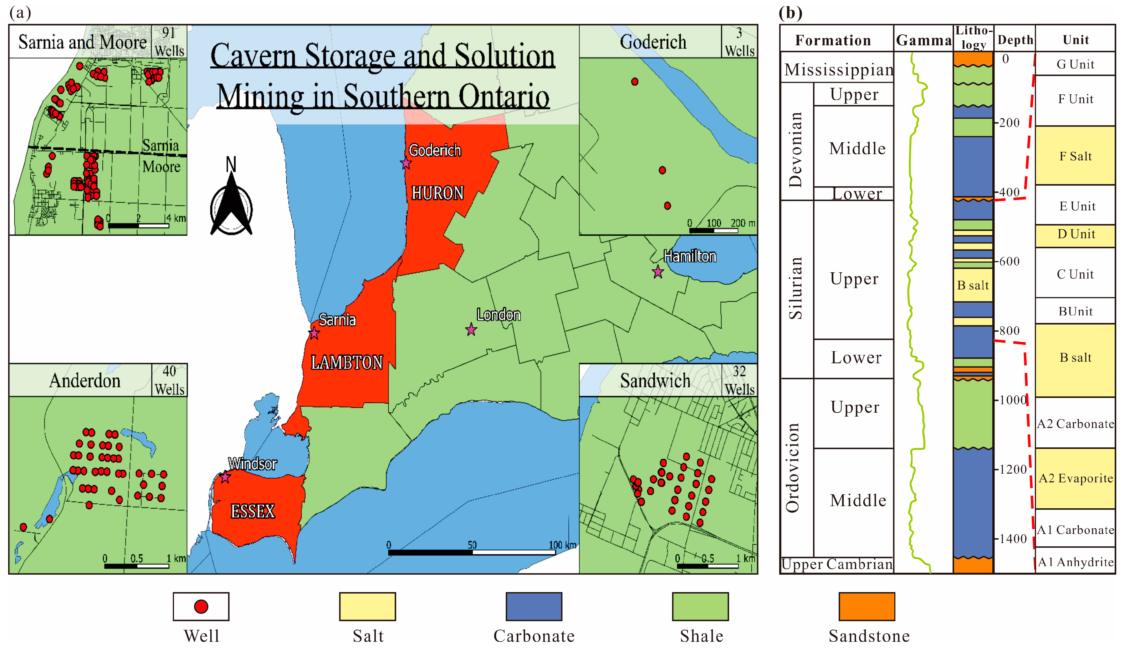
Figure 2.
Conceptual model of underground hydrogen/hydrocarbon storage in salt caverns (modified from [16]).
Figure 2.
Conceptual model of underground hydrogen/hydrocarbon storage in salt caverns (modified from [16]).
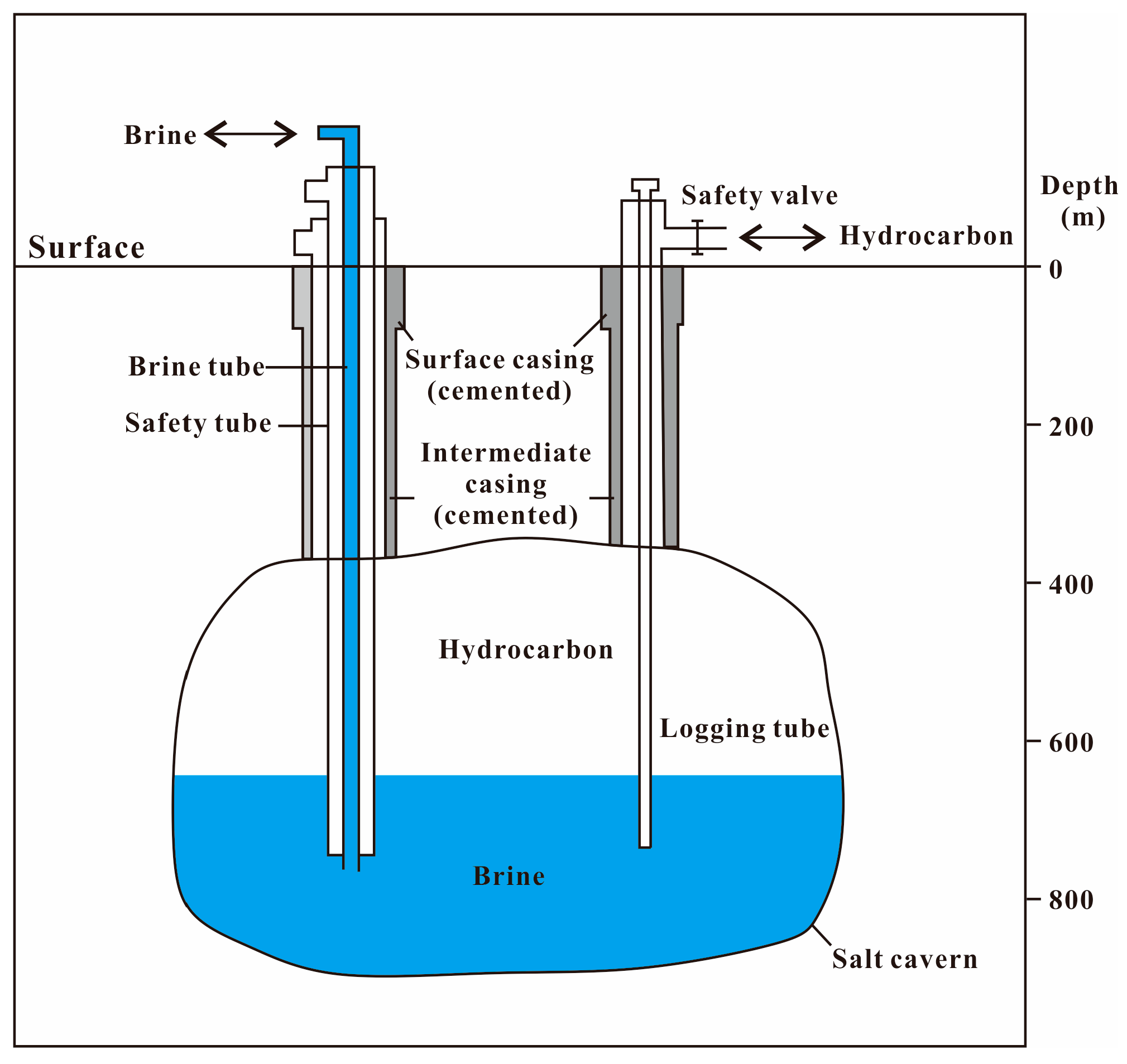
Figure 3.
The creep deformation and diapirs of rock salt (modified from [16]).
Figure 3.
The creep deformation and diapirs of rock salt (modified from [16]).
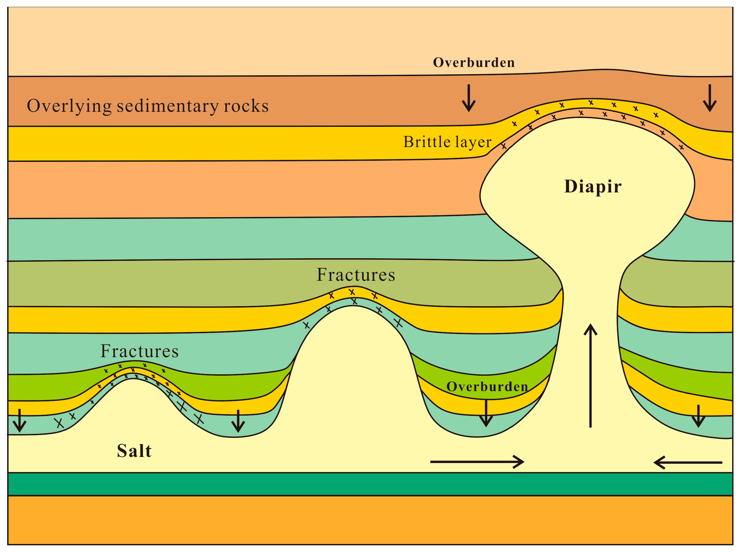
Figure 4.
Distribution of cavern volumes in Ontario [17].
Figure 4.
Distribution of cavern volumes in Ontario [17].
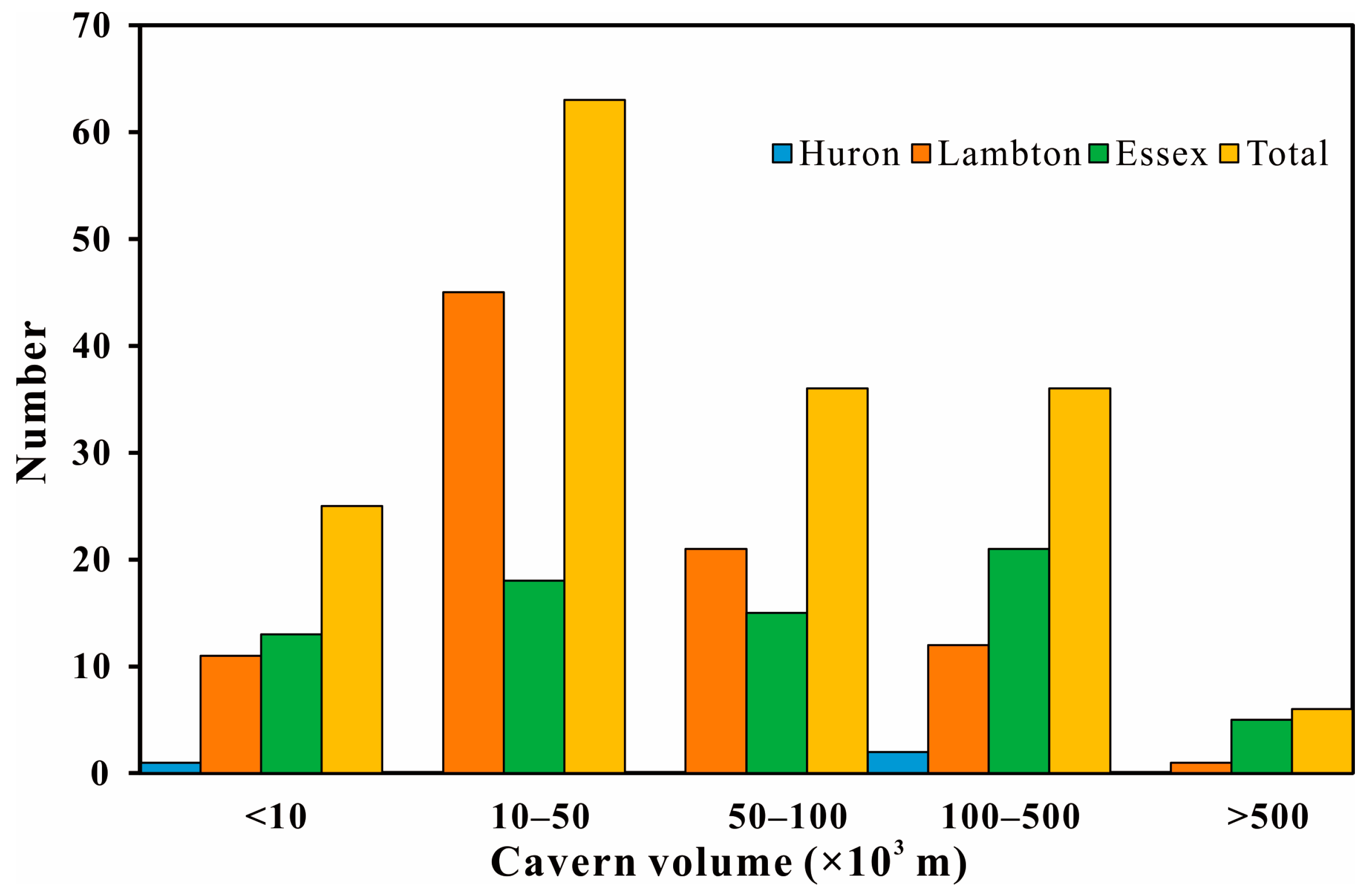
Figure 5.
Conceptual design of salt cavern [9].
Figure 5.
Conceptual design of salt cavern [9].
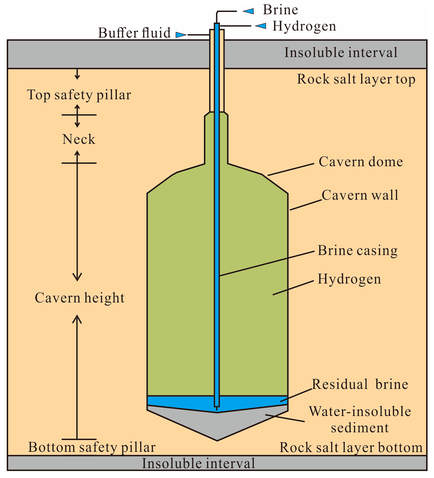
Figure 6.
The estimated internal pressure in terms of depths in salt cavern (modified from [11]).
Figure 6.
The estimated internal pressure in terms of depths in salt cavern (modified from [11]).


Table 1.
Cavern volume of Huron, Lambton, and Essex counties in Ontario [17].
Table 1.
Cavern volume of Huron, Lambton, and Essex counties in Ontario [17].
| Average Volume (×105 m3) | Standard Deviation (×105 m3) | Total Volume (×105 m3) | |
|---|---|---|---|
| Huron | 1.96 | 1.38 | 5.88 |
| Lambton | 0.76 | 1.73 | 69.38 |
| Essex | 1.38 | 2.20 | 99.02 |
| Overall | 1.05 | 1.97 | 174.27 |
Disclaimer/Publisher’s Note: The statements, opinions and data contained in all publications are solely those of the individual author(s) and contributor(s) and not of MDPI and/or the editor(s). MDPI and/or the editor(s) disclaim responsibility for any injury to people or property resulting from any ideas, methods, instructions or products referred to in the content. |
© 2023 by the authors. Licensee MDPI, Basel, Switzerland. This article is an open access article distributed under the terms and conditions of the Creative Commons Attribution (CC BY) license (https://creativecommons.org/licenses/by/4.0/).
Share and Cite
MDPI and ACS Style
Hui, S.; Yin, S.; Pang, X.; Chen, Z.; Shi, K. Potential of Salt Caverns for Hydrogen Storage in Southern Ontario, Canada. Mining 2023, 3, 399-408. https://doi.org/10.3390/mining3030024
AMA Style
Hui S, Yin S, Pang X, Chen Z, Shi K. Potential of Salt Caverns for Hydrogen Storage in Southern Ontario, Canada. Mining. 2023; 3(3):399-408. https://doi.org/10.3390/mining3030024
Chicago/Turabian StyleHui, Shasha, Shunde Yin, Xiongqi Pang, Zhuoheng Chen, and Kanyuan Shi. 2023. "Potential of Salt Caverns for Hydrogen Storage in Southern Ontario, Canada" Mining 3, no. 3: 399-408. https://doi.org/10.3390/mining3030024