Article

Magnesium Sublimation for Growing Thin Films and Conformal Coatings on 1D Nanostructures

1
Department of Physics, Oklahoma State University, Stillwater, OK 74078-3072, USA
2
School of Mechanical and Aerospace Engineering, Oklahoma State University, Stillwater, OK 74074-3072, USA
*
Author to whom correspondence should be addressed.
Nanomanufacturing 2022, 2(4), 186-193; https://doi.org/10.3390/nanomanufacturing2040013
Submission received: 24 August 2022 / Revised: 21 September 2022 / Accepted: 3 October 2022 / Published: 10 October 2022
(This article belongs to the Special Issue Feature Papers for Nanomanufacturing)

Abstract

:
A method to conformally coat silica nanosprings with magnesium via sublimation at 450 °C has been developed. In addition, Mg thin films were grown on Si(100) using this method to determine the effects of substrate morphology (nanoscale curvatures vs. planar) on the interfacial morphology of the Mg coating. High-resolution/powder X-ray diffraction (HRXRD/PXRD) on both the Mg-coated NS and the thin film revealed the presence of Mgand MgO due to exposure of the samples to air. Scanning electron microscopy (SEM) and energy dispersive spectroscopy (EDS) confirmed the presence of Mg on the nanosprings. Elemental mapping with TEM-EDS verified that Mg uniformity and conformally coats the nanosprings. Nanocrystallinity of the Mg coating on the nanosprings was determined to be polycrystalline by TEM and selected area electron diffraction (SAED). In contrast, the process produces large micron-scale crystals on planar surfaces.

1. Introduction

Coating one-dimensional (1D) nanostructures such as silica nanosprings (NS), nanowires, nanorods, or nanotubes with different metal, semiconductor, or insulating coatings can produce nanomaterials with unique capabilities and lead to a wealth of technological uses. In recent years, 1D nanostructure-based devices such as those based on zinc oxide [1,2], silicon [3], and silver nanowires [4,5] have shown strengthened physical, optical, and electrical properties after the application of various coatings. The conformal coating of 1D nanostructures requires either liquid immersion solgel deposition [6,7,8,9] or chemical vapor deposition of one type or another [10,11,12,13,14]. The purpose of this study is to develop a cost effective and straightforward method for conformally coating 1D nanostructures such as NS with magnesium. Duan et al. [15] have outlined the many desirable properties of Mg, including its excellent optical properties for nanoplasmonics [15,16,17] and its appeal in reversible metal to dielectric states when exposed to hydrogen [18,19,20], as well as superior structural properties for applications in biotechnology and the aerospace/automotive sector [21]. In the case of NS, Mg coatings may impart unique chiral optical properties for enhanced gas sensing [22,23,24] or other dynamic properties with significant technological impact.
Magnesium is an excellent material for conformal coating of 1D nanostructures due to its low sublimation temperature of 327 °C at 10−4 Torr, as well as its immensely interesting properties [22,25,26,27,28,29,30]. Magnesium at low pressures behaves almost like a semipermanent gas, which is unusual for metals; that facilitates conformal coatings on various structures [31]. There are, of course, methods of Mg deposition widely used, including atomic layer deposition (ALD) and molecular beam epitaxy (MBE). However, these methods have their drawbacks. For example, ALD of Mg is mainly used for doping semiconductors using magnesium bis(cyclopentadienyl) (MgCp2), where plasma enhancement is required for the process [32,33]. Molecular beam epitaxy of Mg and MgO is well suited for thin film deposition but is better suited for line-of-sight deposition [32,34]. The advantages of the method presented here are its simplicity and cost effectiveness as well as the fact that it does not require a significant investment in capital equipment.

2. Experimental Setup

Mg deposition was carried out in a simple vacuum system schematically represented in Figure 1. It consists of a bench top vacuum chamber—in this case, an 8-inch vacuum chamber with a removable flange on the top for inserting the sample. Inside the chamber is a boron nitride heater, although any heater capable of reaching 450 °C will suffice. The system is pumped with a turbomolecular pump capable of obtaining a base chamber pressure of <   2 × 10 4 Torr. A detailed explanation of the Au catalyst assisted vapor–liquid–solid growth of the silica nanosprings can found in [35,36,37]. A NS sample placed facing upward in a 10 mL quartz crucible along with approximately 20 mg of Mg shaved from a Mg pellet (Ted Pella). Laying the sample flat on the bottom of the crucible ensures good thermal contact and therefore at the same temperature. Note that this is necessary to promote Mg adsorption onto the NS because of Mg’s semipermanent gas properties [31]. This placement also keeps the sample out of the line-of-sight of Mg deposition that is predominantly upward, thereby eliminating over deposition of Mg on the top surface of the sample, which in the case of the NS mat can clog the spaces between NS and lead to their encapsulation instead of a conformal coating. The crucible is covered with a ceramic plate and placed on the heater. The ceramic plate helps to maintain a high vapor concentration of Mg in the crucible. A type K thermocouple is mounted on the heater next to the crucible. The heater is then raised to 450 °C and remains so for a dwell time of 10–15 min. The silica NS samples consisting of a mat of NS grown on Si(100) via a modified vapor–liquid–solid (VLS) method discussed by McIlroy et al. in depth in [38]. The thickness of the mat of NS is approximately 30 mm. When coating a bare Si(100) substrate, it was attached to the ceramic top plate facing toward the bottom of the crucible.

3. Materials Analysis

X-ray photoelectron spectroscopy (XPS) was performed in an ultrahigh vacuum (UHV) system with a base pressure of 6.0 × 10⁻¹⁰ Torr. The XPS spectra were acquired using the monochromatic Al-Kα emission line from a dual anode X-ray source (Physical Electronics XR 04-548) operated at 300 W and an incident angle of 54.7°. The kinetic energy of the photoelectrons was measured with an Omicron EA 125 hemispherical electron energy analyzer with a resolution of 0.02 eV. High-resolution thin film X-ray diffraction (HRXRD) XRD pattern of Mg/Si(100) were acquired with a Bruker D8 Advanced XRD using the Cu Ka1 emission line and powder X-ray diffraction (PXRD) XRD pattern of Mg-coated NS were acquired with an Rigaku Miniflex Diffractometer also using the Cu Ka1 emission line. Scanning Electron Microscopy (SEM) micrographs were acquired with an FEI Quanta 600 with Bruker EDS and HKL EBSD. The spot size resolution for SEM was between 2–3 spot resolution and the voltage between 10–15 kV. Transmission electron microscopy (TEM) and select area electron diffraction (SAED) of the coated NS were acquired with a JEOL JEM-2100 transmission electron microscope with an EVEX X-ray microanalysis system.

4. Results and Discussion

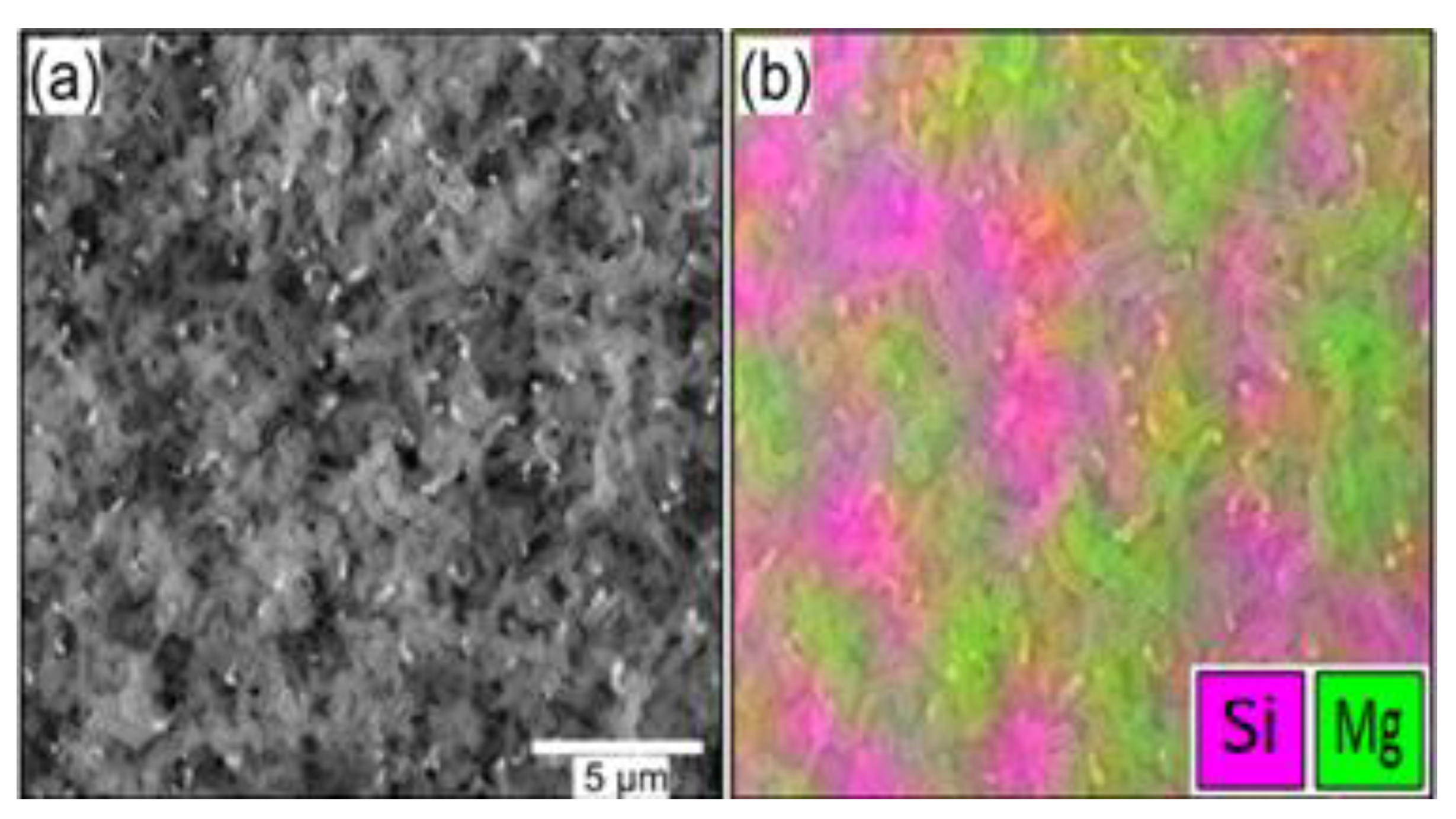
An SEM micrograph and the corresponding EDS overlay of Mg-coated NS are displayed in Figure 2a,b. The EDS overlay demonstrates that Mg is present on the topmost NS of the mat. The patches of high Si concentration correspond to thinner regions of the mat and likely signal from the Si substrate in addition to the NS. The bright spots in Figure 2a are Au NP at the tip of the NS that serve as the catalyst for their VLS growth. An XPS survey scan of Mg/Si(100) is displayed in Figure 3. The peaks at binding energies of 100 eV and 153 eV are the Si 2p and 2s core level states, respectively, of the substrate. The C 1s core level is extremely weak, indicative of the cleanliness of the process. The O 1s core level state is at the expected binding energy of 532 eV. The Mg 1s core level state is at binding energy of 1305.3 eV (see inset in Figure 3), which is close to the literature value of 1304.5 eV for MgO [39]. The observation of the Si 2p1/2 and 2p3/2 core level states at 104 eV and 152 eV, respectively, indicates that the Mg layer is no thicker than 10 nm and, therefore, the interfacial morphology should be like that of the Mg-coated NS. The conclusion is that the surface of the Mg film has oxidized upon exposure to air, which is to be expected. XPS analysis was not performed on the Mg-coated NS due to the low signal-to-noise of the Mg 1s and that scattering from the nonuniform surface presented by the nanosprings further exacerbates the poor signal-to-noise.
HRXRD and PXRD were used to determine the microstructure of the Mg thin film and the Mg-coated NS sample, respectively. Displayed in Figure 4a are the HRXRD pattern for Mg/Si(100) and the PXRD of Mg-coated NS, which both exhibit a peak at 69.46°, just off the Si(100) main peak, corresponding to hexagonal Mg(OH)2 [40,41]. Its presence indicates that during the initial phase of deposition, Mg interacts with OH groups on the surface of the silica NS [42] and the native oxide of the Si(100) substrate [43]. However, the Mg coating on both samples eventually becomes pure Mg, as evident by the Mg(002) and Mg(102) peaks at 34.5° and 47.7°, respectively, in Figure 4b for the Mg thin film and the Mg(102) peak at 47.7° in Figure 4c for the Mg-coated NS. The Mg(002) peak for the Mg-coated NS is partially obscured by the broad amorphous SiO2 peak of the silica NS between 35° and 42° [44]. The additional, unmarked peaks in Figure 4c correspond to Au used as the catalyst for NS growth, where the Au nanoparticles is located at the end of the nanosprings.
To confirm the conformal nature of the Mg coating of the NS, high-resolution TEM analysis was performed. Figure 5a is a TEM micrograph of a single Mg-coated NS. Figure 5b is the reference spectrum for the EDS scan in Figure 5c. It is apparent from the EDS map that Mg (red) conformally coats the entire NS. High-resolution TEM and SAED were performed on the Mg-coated NS to confirm the morphology and crystallinity of the Mg coating, which also provided insight into the chemical composition of the Mg, i.e., metallic Mg, MgO or a combination of both. The TEM image in Figure 6 shows that the coating consists of Mg nano-crystallites of less than 100 nm in size (red circles). The HRTEM micrograph of a single Mg crystallite is displayed in Figure 6b, and the corresponding SAED pattern in Figure 6c. The SAED patterns have been quantified using standard hexagonal Mg (h-Mg) [45,46] and cubic MgO (c-MgO) [47,48], having the space group of P63/mmc, and FM 3 ¯ M, respectively. The lattice parameters used for h-Mg are a = 3.203 Å and c = 5.127 Å), and for c-MgO, they are a = b = c = 3.010 Å. Magnesium oxide is assumed based on the XPS analysis and the oxidation properties of Mg. The h-Mg SAED ring patterns in Figure 6c correspond to the (101), (002) and (100) crystal planes. The additional rings correspond to the (111), (200), (220), and (311) crystal planes of c-MgO. Further quantification of standard trigonal Mg(OH)2 and cubic Au having space groups P 3 ¯ m1 and FM 3 ¯ M, respectively, was carried out. The presence of Mg(OH)2 is supported by our XPS and XRD observations, where Au’s presence as a catalyst has been subsequently discussed. Note that because of the amorphous structure of the silica NS, it does not contribute to the SAED pattern.
Based on XRD and SAED analysis, we propose the following description of Mg sublimation deposition. During the initial phase of Mg adsorption, it reacts with the surface of the silica NS or the native oxide of the Si substrate forming MgO and Mg(OH)2, where the presence of Mg(OH)2 is confirmed by the observation of its (103) peak in the XRD pattern of the NS and thin film in Figure 4a and its (002) and (111) rings in the SAED pattern in Figure 6c. At the interface, it is assumed given the reactivity of Mg with O. Eventually, the growth transitions to Mg. The formation of nanocrystals on the NS is consistent with previous work on GaN-coated NS [49], where the amorphous surface and its curvature produce stresses that favor crystallite formation over epitaxial growth. Based on the results of this study, we can conclude that in the presence of OH groups on the surface of the two supports, Mg(OH)2 (brucite) is initially formed and subsequently transitions to Mg.

5. Conclusions

We have developed a simple sublimation-based process for conformally coating 1D nanostructures with Mg. XPS analysis indicates that the topmost layer of Mg is oxidized, which is to be expected given the proclivity of Mg to oxidize in air. The Mg (002), (102), crystal planes were observed for the thin film and the Mg (102) for the Mg-coated NS. X-ray diffraction peaks corresponding to Mg(OH)2 were observed for the Mg thin film and Mg-coated NS. Optical examination of the Mg thin film revealed the formation of large crystallites. SEM-EDS mapping of a mat of NS showed that the Mg sublimation process coats the entire mat. High-resolution TEM and SAED analysis of a single Mg-coated NS revealed that the Mg coating is polycrystalline, consisting of sub-100 nm nanocrystals. Moreover, from SAED analysis of the Mg-coated NS, it was determined that the coating is Mg(OH)2 at the interface with the NS, that it converts to h-Mg, and that it is capped with c-MgO, where the oxide layer is attributed to post growth oxidation upon exposure to air. This process can readily be used to coat any variety of 1D nanostructures with Mg. The process has the advantage of minimal investment in capital equipment or expensive chemical precursors such as those used in atomic layer deposition of Mg. We hypothesize that the formation of MgO can be mitigated by depositing a thin Al2O3 layer prior to air exposure. Finally, we suggest that the initial formation of Mg(HO)2 on hydroxyl terminated surfaces can be exploited to form ultrathin films of unique MgO-based minerals.

Author Contributions

Conceptualization, D.N.M. and A.J.A.; methodology, D.N.M. and A.J.A.; formal analysis, A.J.A., N.P.D., E.E., A.K.G., J.R. and H.C.H.; writing original—original draft preparation, A.J.A.; writing—review and editing, A.J.A., N.P.D., E.E., R.S. and D.N.M.; supervision, D.N.M.; funding acquisition, D.N.M. All authors have contributed in one part or another in the acquisition of data, data analysis and preparation of the manuscript. All authors have read and agreed to the published version of the manuscript.

Funding

Funding was provided by the Office of Naval Research (No. N00014-20-1-2433).

Data Availability Statement

The data that support the findings of this study are available from the corresponding author upon reasonable request.

Acknowledgments

Images were obtained from Venture One Electron Microcopy lab. The authors especially thank Lisa Whitworth and Brent Johnson.

Conflicts of Interest

The authors declare no conflict of interest.

References

  1. Wang, L.; Li, J.; Wang, Y.; Yu, L.; Tang, X.; Zhang, Y.; Wang, S.; Wei, C. Construction of 1D SnO2-coated ZnO nanowire heterojunction for their improved n-butylamine sensing performances. Sci. Rep. 2016, 6, 35079. [Google Scholar] [CrossRef] [PubMed] [Green Version]
  2. Guo, J.; Zhang, J.; Zhu, M.; Ju, D.; Xu, H.; Cao, B. High-performance gas sensor based on ZnO nanowires functionalized by Au nanoparticles. Sens. Actuators B Chem. 2014, 199, 339–345. [Google Scholar] [CrossRef]
  3. Kong, B.H.; Choi, M.K.; Cho, H.K.; Kim, J.H.; Baek, S.; Lee, J.-H. Conformal Coating of Conductive ZnO:Al Films as Transparent Electrodes on High Aspect Ratio Si Microrods. Electrochem. Solid-State Lett. 2009, 13, K12. [Google Scholar] [CrossRef]
  4. Lin, S.; Wang, H.; Zhang, X.; Wang, D.; Zu, D.; Song, J.; Liu, Z.; Huang, Y.; Huang, K.; Tao, N.; et al. Direct spray-coating of highly robust and transparent Ag nanowires for energy saving windows. Nano Energy 2019, 62, 111–116. [Google Scholar] [CrossRef]
  5. Zhi, J.; Zhao, W.; Liu, X.; Chen, A.; Liu, Z.; Huang, F. Highly Conductive Ordered Mesoporous Carbon Based Electrodes Decorated by 3D Graphene and 1D Silver Nanowire for Flexible Supercapacitor. Adv. Funct. Mater. 2014, 24, 2013–2019. [Google Scholar] [CrossRef]
  6. Rajabi, N.; Wojcik, P.M.; Khanal, L.R.; Qiang, Y.; McIlroy, D.N. A comparison of the morphological and electrical properties of sol-gel dip coating and atomic layer deposition of ZnO on 3D nanospring mats. Mater. Res. Express 2018, 6, 035902. [Google Scholar] [CrossRef]
  7. Liang, H.-W.; Liu, S.; Yu, S.-H. Controlled Synthesis of One-Dimensional Inorganic Nanostructures Using Pre-Existing One-Dimensional Nanostructures as Templates. Adv. Mater. 2010, 22, 3925–3937. [Google Scholar] [CrossRef]
  8. Xia, Y.; Yang, P.; Sun, Y.; Wu, Y.; Mayers, B.; Gates, B.; Yin, Y.; Kim, F.; Yan, H. One-Dimensional Nanostructures: Synthesis, Characterization, and Applications. Adv. Mater. 2003, 15, 353–389. [Google Scholar] [CrossRef]
  9. Qiu, J.; Yu, W.; Gao, X.; Li, X. Sol–gel assisted ZnO nanorod array template to synthesize TiO2 nanotube arrays. Nanotechnology 2006, 17, 4695–4698. [Google Scholar] [CrossRef]
  10. Meng, X.; Banis, M.N.; Geng, D.; Li, X.; Zhang, Y.; Li, R.; Abou-Rachid, H.; Sun, X. Controllable atomic layer deposition of one-dimensional nanotubular TiO2. Appl. Surf. Sci. 2013, 266, 132–140. [Google Scholar] [CrossRef]
  11. Dvorak, F.; Zazpe, R.; Krbal, M.; Sopha, H.; Prikryl, J.; Ng, S.; Hromadko, L.; Bures, F.; Macak, J.M. One-dimensional anodic TiO2 nanotubes coated by atomic layer deposition: Towards advanced applications. Appl. Mater. Today 2019, 14, 1–20. [Google Scholar] [CrossRef]
  12. Marichy, C.; Bechelany, M.; Pinna, N. Atomic Layer Deposition of Nanostructured Materials for Energy and Environmental Applications. Adv. Mater. 2012, 24, 1017–1032. [Google Scholar] [CrossRef] [PubMed]
  13. Knez, M.; Nielsch, K.; Niinistö, L. Synthesis and Surface Engineering of Complex Nanostructures by Atomic Layer Deposition. Adv. Mater. 2007, 19, 3425–3438. [Google Scholar] [CrossRef]
  14. Chaaya, A.; Bechelany, M.; Balme, S.; Miele, P. ZnO 1D nanostructures designed by combining atomic layer deposition and electrospinning for UV sensor applications. J. Mater. Chem. A 2014, 2, 20650–20658. [Google Scholar] [CrossRef]
  15. Duan, X.; Liu, N. Magnesium for Dynamic Nanoplasmonics. Acc. Chem. Res. 2019, 52, 1979–1989. [Google Scholar] [CrossRef] [Green Version]
  16. Ringe, E. Shapes, Plasmonic Properties, and Reactivity of Magnesium Nanoparticles. J. Phys. Chem. C Nanomater. Interfaces 2020, 124, 15665–15679. [Google Scholar] [CrossRef]
  17. Biggins, J.S.; Yazdi, S.; Ringe, E. Magnesium Nanoparticle Plasmonics. Nano Lett. 2018, 18, 3752–3758. [Google Scholar] [CrossRef]
  18. Jain, P.; Lal, C.; Jain, A. Hydrogen storage in Mg: A most promising material. Int. J. Hydrogen Energy 2010, 35, 5133–5144. [Google Scholar] [CrossRef]
  19. Luo, Q.; Li, J.; Li, B.; Liu, B.; Shao, H.; Li, Q. Kinetics in Mg-based hydrogen storage materials: Enhancement and mechanism. J. Magnes. Alloys 2019, 7, 58–71. [Google Scholar] [CrossRef]
  20. Shao, H.; Xin, G.; Zheng, J.; Li, X.; Akiba, E. Nanotechnology in Mg-based materials for hydrogen storage. Nano Energy 2012, 1, 590–601. [Google Scholar] [CrossRef]
  21. Gupta, M.; Ling, S.N.M. Magnesium, Magnesium Alloys, and Magnesium Composites; John Wiley & Sons: Hoboken, NJ, USA, 2011. [Google Scholar]
  22. Duan, X.; Yue, S.; Liu, N. Understanding complex chiral plasmonics. Nanoscale 2015, 7, 17237–17243. [Google Scholar] [CrossRef] [PubMed]
  23. Mohammadi, E.; Tsakmakidis, K.L.; Askarpour, A.N.; Dehkhoda, P.; Tavakoli, A.; Altug, H. Nanophotonic Platforms for Enhanced Chiral Sensing. ACS Photonics 2018, 5, 2669–2675. [Google Scholar] [CrossRef]
  24. Duan, X.; Kamin, S.; Sterl, F.; Giessen, H.; Liu, N. Hydrogen-Regulated Chiral Nanoplasmonics. Nano Lett. 2016, 16, 1462–1466. [Google Scholar] [CrossRef] [PubMed]
  25. Jeong, H.-H.; Mark, A.G.; Fischer, P. Magnesium plasmonics for UV applications and chiral sensing. Chem. Commun. 2016, 52, 12179–12182. [Google Scholar] [CrossRef] [Green Version]
  26. Sterl, F.; Strohfeldt, N.; Walter, R.; Griessen, R.; Tittl, A.; Giessen, H. Magnesium as Novel Material for Active Plasmonics in the Visible Wavelength Range. Nano Lett. 2015, 15, 7949–7955. [Google Scholar] [CrossRef]
  27. Gutiérrez, Y.; de la Osa, R.A.; Ortiz, D.; Saiz, J.; González, F.; Moreno, F. Plasmonics in the Ultraviolet with Aluminum, Gallium, Magnesium and Rhodium. Appl. Sci. 2018, 8, 64. [Google Scholar] [CrossRef] [Green Version]
  28. Arrowsmith, M.; Hill, M.S.; Kociok-Köhn, G. Magnesium Catalysis of Imine Hydroboration. Chem. Eur. J. 2013, 19, 2776–2783. [Google Scholar] [CrossRef]
  29. Yang, D.; Wang, L.; Li, D.; Wang, R. Magnesium Catalysis in Asymmetric Synthesis. Chem 2019, 5, 1108–1166. [Google Scholar] [CrossRef]
  30. Froes, F.H.; Eliezer, D.; Aghion, E. The science, technology, and applications of magnesium. JOM 1998, 50, 30–34. [Google Scholar] [CrossRef]
  31. Knight, L.B.; Brittain, R.D.; Duncan, M.; Joyner, C.H. Unusual behavior of vaporized magnesium under low pressure conditions. J. Phys. Chem. 1975, 79, 1183–1190. [Google Scholar] [CrossRef]
  32. Uddin, G.M.; Ziemer, K.S.; Zeid, A.; Lee, Y.-T.T.; Kamarthi, S. Process control model for growth rate of molecular beam epitaxy of MgO (111) nanoscale thin films on 6H-SiC (0001) substrates. Int. J. Adv. Manuf. Technol. 2017, 91, 907–916. [Google Scholar] [CrossRef]
  33. Song, J.-G.; Park, J.; Yoon, J.; Woo, H.; Ko, K.; Lee, T.; Hwang, S.-H.; Myoung, J.-M.; Kim, K.; Jang, Y.; et al. Plasma enhanced atomic layer deposition of magnesium oxide as a passivation layer for enhanced photoluminescence of ZnO nanowires. J. Lumin. 2014, 145, 307–311. [Google Scholar] [CrossRef]
  34. Herman, M.A.; Sitter, H. Molecular Beam Epitaxy: Fundamentals and Current Status; Springer Science & Business Media: Berlin/Heidelberg, Germany, 2012. [Google Scholar]
  35. Wang, L.; Major, D.; Paga, P.; Zhang, D.; Norton, M.G.; McIlroy, D.N. High yield synthesis and lithography of silica-based nanospring mats. Nanotechnology 2006, 17, S298–S303. [Google Scholar] [CrossRef]
  36. Corti, G.; Brown, J.; Rajabi, N.; McIlroy, D.N. Threefold growth efficiency improvement of silica nanosprings by using silica nanosprings as a substrate. Nanotechnology 2018, 29, 115604. [Google Scholar] [CrossRef] [PubMed]
  37. Wojcik, P.M.; Bakharev, P.V.; Corti, G.; McIlroy, D.N. Nucleation, evolution, and growth dynamics of amorphous silica nanosprings. Mater. Res. Express 2017, 4, 015004. [Google Scholar] [CrossRef]
  38. McIlroy, D.N.; Zhang, D.; Kranov, Y.; Norton, M.G. Nanosprings. Appl. Phys. Lett. 2001, 79, 1540. [Google Scholar] [CrossRef]
  39. Corneille, S.; He, J.-W.; Goodman, D.W. XPS characterization of ultra-thin MgO films on a Mo(100) surface. Surf. Sci. 1994, 306, 269–278. [Google Scholar] [CrossRef]
  40. Wang, J.A.; Novaro, O.; Bokhimi, X.; López, T.; Gómez, R.; Navarrete, J.; Llanos, M.E.; López-Salinas, E. Characterizations of the thermal decomposition of brucite prepared by sol–gel technique for synthesis of nanocrystalline MgO. Mater. Lett. 1998, 35, 317–323. [Google Scholar] [CrossRef]
  41. Nied, D.; Enemark-Rasmussen, K.; L’Hopital, E.; Skibsted, J.; Lothenbach, B. Properties of magnesium silicate hydrates (M-S-H). Cem. Concr. Res. 2016, 79, 323–332. [Google Scholar] [CrossRef]
  42. Schmiesing, N.C.; Corti, G.; Sommers, A.D. Water Condensation and Droplet Shedding Behavior on Silica-Nanospring-Coated Tubes. ACS Appl. Mater. Interfaces 2020, 12, 17046–17054. [Google Scholar] [CrossRef]
  43. Morita, M.; Ohmi, T.; Hasegawa, E.; Kawakami, M.; Ohwada, M. Growth of native oxide on a silicon surface. J. Appl. Phys. 1990, 68, 1272–1281. [Google Scholar] [CrossRef]
  44. Brichni, A.; Hammi, H.; Aggoun, S.; Mnif, A. Optimisation of magnesium oxychloride cement properties by silica glass. Adv. Cem. Res. 2016, 28, 654–663. [Google Scholar] [CrossRef]
  45. Paik, B.; Jones, I.P.; Walton, A.; Mann, V.; Book, D.; Harris, I.R. MgH2 → Mg phase transformation driven by a high-energy electron beam: An in situ transmission electron microscopy study. Philos. Mag. Lett. 2010, 90, 1–7. [Google Scholar] [CrossRef]
  46. Persson, K. Materials Data on Mg (SG:194) by Materials Project. 2015. [CrossRef]
  47. Persson, K. Materials Data on MgO (SG:225) by Materials Project. 2014. [CrossRef]
  48. Kim, G.; Dahmen, U.; Searcy, A.W. Structural Transformations in the Decomposition of Mg(OH)2 and MgCO3. J. Am. Ceram. Soc. 1987, 70, 146–154. [Google Scholar] [CrossRef]
  49. Austin, J.; Echeverria, E.; Wagle, P.; Mainali, P.; Meyers, D.; Gupta, A.K.; Sachan, R.; Prassana, S.; McIlroy, D.N. High-Temperature Atomic Layer Deposition of GaN on 1D Nanostructures. Nanomaterials 2020, 10, 2434. [Google Scholar] [CrossRef] [PubMed]
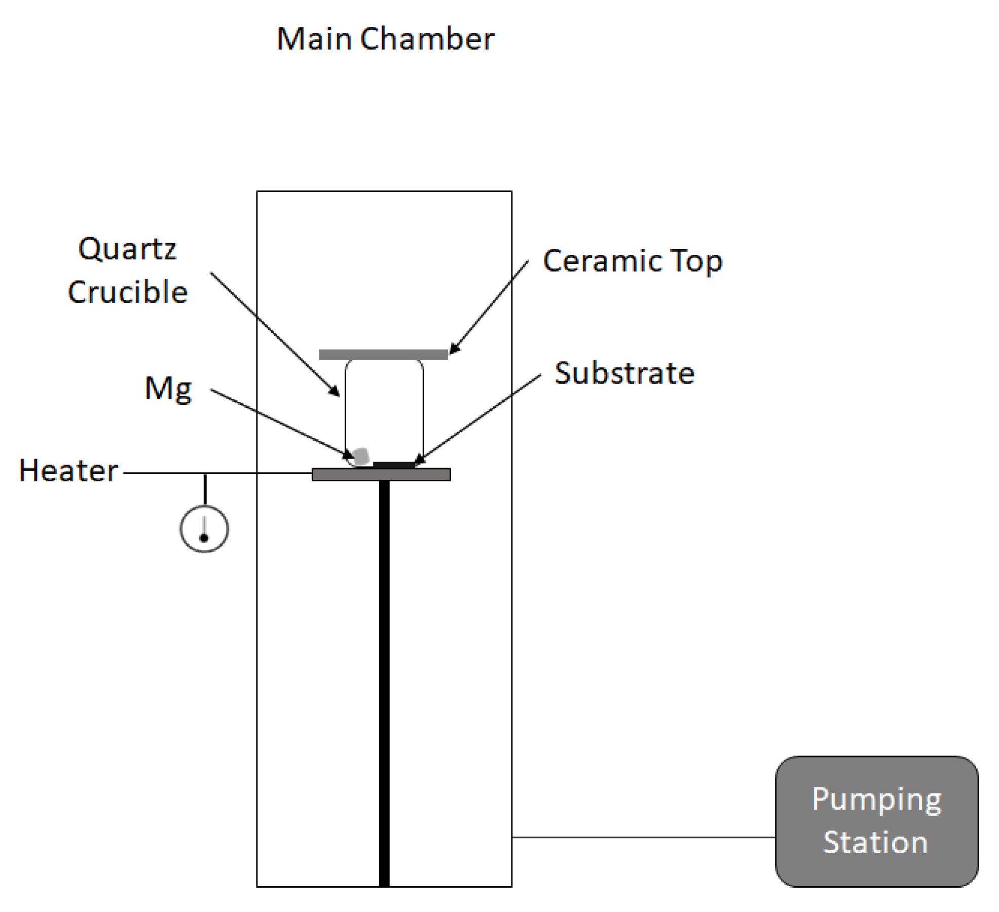
Figure 1. Vacuum chamber used for sublimation deposition of Mg onto silica nanosprings. The sample and Mg pellets are placed in a quartz crucible capped with a ceramic disk.
Nanomanufacturing 02 00013 g001
Figure 2. (a) An SEM micrograph of Mg-coated NS and (b) the corresponding EDS map of Mg and Si.
Nanomanufacturing 02 00013 g002
Figure 3. An XPS survey scan of the Mg thin film on Si(100). The inset is a high-resolution XPS spectrum of the Mg 1s core level state.
Nanomanufacturing 02 00013 g003
Figure 4. HRXRD and PXRD patterns of Mg on Si(100) wafers and nanosprings, respectively, where (a) shows a scan from 68.5 to 70 degrees with a sharp Mg(OH)2 peak present and (b) a broader scan from 30 to 65 degrees where Mg(002) and Mg(102) orientations are present for the thin film sample and (c) Mg(102) is also observed in the PXRD spectrum of the Mg-coated nanosprings.
Nanomanufacturing 02 00013 g004
Figure 5. TEM micrographs of (a) a single Mg-coated NS coated in Mg. (b) A reference TEM micrograph of the end of the NS used for EDS mapping. (c) The corresponding EDS map of the end of the NS in (b), where red corresponds to Mg and green to Si.
Nanomanufacturing 02 00013 g005
Figure 6. (a) TEM micrograph of a silica NS, where red circles indicate Mg nanocrystals (NC) on the surface. (b) A high-resolution TEM micrograph of a Mg NC and (c) the corresponding SAED pattern consisting of rings of h-Mg (gold) and the c-MgO (green).
Nanomanufacturing 02 00013 g006
Publisher’s Note: MDPI stays neutral with regard to jurisdictional claims in published maps and institutional affiliations.