Article

Enhanced Performance of TiO2 Composites for Solar Cells and Photocatalytic Hydrogen Production

School of Physics and Optoelectronic Engineering, Yangtze University, Jingzhou 434023, China
*
Author to whom correspondence should be addressed.
Nanoenergy Adv. 2025, 5(4), 14; https://doi.org/10.3390/nanoenergyadv5040014
Submission received: 23 July 2025 / Revised: 23 October 2025 / Accepted: 23 October 2025 / Published: 28 October 2025

Abstract

Titanium dioxide (TiO2) is widely used in solar cells and photocatalysts, given its excellent photoactivity, low cost, and high structural, electronic, and optical stability. Here, a novel TiO2 composite was prepared by coating TiO2 inverse opal (IO) with TiO2 nanorods (NRs). With a porous three-dimensional network structure, the composite exhibited higher light absorption; enhanced the separation of the electron–hole pairs; deepened the infiltration of the electrolyte; better transported and collected charge carriers; and greatly improved the power conversion efficiency (PCE) of the quantum-dot sensitized solar cells (QDSSCs) based on it, while also boosting its own photocatalytic hydrogen generation efficiency. A very high PCE of 12.24% was achieved by QDSSCs utilizing CdS/CdSe sensitizer. Furthermore, the TiO2 composite exhibited high photocatalytic activity with a H2 release rate of 1080.2 μ mol h−1 g−1, several times that of bare TiO2 IO or TiO2 NRs.

1. Introduction

Titanium dioxide (TiO2) is widely recognized as a fundamental material in renewable energy technologies due to its excellent photoactivity, chemical stability, low cost, and environmental friendliness. Its applications span photovoltaics and photocatalysis, where its tunable electronic and optical properties play a critical role [1,2,3,4,5]. In particular, TiO2 serves as a key electron transport layer (ETL) in various solar cell architectures. A landmark development was achieved by O’Regan and Grätzel in 1991 with the introduction of dye-sensitized solar cells (DSSCs), which utilized mesoporous TiO2 nanoparticles to achieve a high surface area and efficient charge separation [6]. This work established the importance of nanostructural engineering for optimizing device performance.
Recent advances in synthesis techniques—including electrodeposition, sol–gel processing, and atomic layer deposition—have enabled precise control over TiO2 film morphology, facilitating the development of structures ranging from dense compact layers to highly porous networks [4,7,8,9,10]. These morphological variations significantly influence charge transport and recombination dynamics. In parallel, quantum dot-sensitized solar cells (QDSSCs) have emerged as a promising alternative to conventional DSSCs, leveraging the size-tunable bandgaps and high absorption coefficients of quantum dots (e.g., CdS, PbS) as sensitizers [11,12,13,14,15]. To maximize performance in QDSSCs, TiO2 nanostructures must be designed to facilitate both quantum dot loading and efficient charge injection. One-dimensional nanostructures such as nanorods and nanotubes have shown reduced charge recombination compared to particulate films [16,17]. Doping strategies (e.g., with N or Ag) have also been employed to extend the optical absorption of TiO2 into the visible range [18,19,20].
In the field of photocatalysis, TiO2 has attracted significant attention as a promising material for solar-driven hydrogen production, owing to its strong redox activity, corrosion resistance, and non-toxicity. Numerous efforts have been made to enhance its photocatalytic efficiency, including elemental doping, composite formation with other metal oxides, and morphological control. Various TiO2 nanoarchitectures—such as nanoparticles, nanofibers, and inverse opal (IO) structures—have been extensively investigated for this purpose [10,20,21,22,23].
In this work, we introduce a novel TiO2-based composite material composed of TiO2 inverse opal structures coated with TiO2 nanorods (NRs). This unique architecture synergistically combines the benefits of a high-surface-area IO framework with the directed charge transport pathways provided by NRs. The present study aims to systematically evaluate the dual functionality of this composite: as a photoanode in QDSSCs and as a photocatalyst for hydrogen evolution. The novelty of this work lies in the integrated design and comparative investigation of the same material across two distinct energy applications, revealing underlying structure–property relationships that contribute to enhanced device performance and catalytic activity. Key results demonstrate a superior performance in both domains, attributable to improved light harvesting, charge separation, and surface reactivity.

2. Experiment

2.1. Materials

Ethanol, methanol, isopropyl alcohol, acetone, hydrochloric acid (HCl), nitric acid (HNO3), ammonia, zinc acetate (Zn(CH3COO)2·2H2O), Titanium (IV) isopropoxide, Triton X-100 and Ti[OCH(CH3)2]4 were obtained from Sinopharm Chemical Reagent Co., Ltd. (Shanghai, China). Sulfide nonahydrate (Na2S·9H2O), sodium selenium (Se), cadmium nitrate tetrahydrate (Cd(NO3)2·4H2O), cadmium sulfate hydrate (CdSO4·8/3H2O), sodium sulfite (Na2SO3), Igepal CO-520, ammonium hexafluorotitanate ((NH4)2TiF6), boric acid (H3BO3), potassium chloride (KCl), nitrilotriacetic acid (C6H9NO6, NTA), sulfur (S), and potassium hydroxide (KOH ≥ 85.0%) were purchased from Sigma Aldrich (St. Louis, MO, USA). The fluorine-doped tin oxide (FTO) glass was acquired from Yingkou OPV Tech New Energy Co., Ltd. (Yingkou, China). Polystyrene (PS) latex microspheres were purchased from Ganzhou Mxene Technology Co., Ltd. (Ganzhou, China). All chemicals utilized were of reagent grade and were employed directly without further purification.

2.2. Preparation of TiO2 Inverse Opal

TiO2 IO was synthesized through liquid-phase deposition utilizing PS microspheres as a template with a controlled diameter [21]. The preparation process involved several key steps. Initially, an aqueous solution containing 0.1 wt% PS microspheres and 0.003 wt% Igepal CO-520 surfactant was sonicated for 30 min to ensure uniform dispersion.
Following this, a cleaned conductive FTO glass substrate was treated with oxygen plasma and then immersed in the PS microsphere dispersion. The substrate was subsequently placed in an oven at 55 °C until the dispersion evaporated, leaving a layer of PS microspheres on the glass. Next, the PS template was coated with TiO2 by immersing the films in an ethanol solution containing 0.12% (w/v) HNO3 and 1.2% (w/v) isopropyl titanate for 5 min. The films were then allowed to dry at room temperature. The thickness of the PS template and the resulting TiO2 IO film could be controlled by adjusting the volume of the infiltrated solution and the drying time. After that, the films were further processed by immersing them in a combined aqueous solution of 0.25 M H3BO3 and 0.2 M (NH4)2TiF6 at 50 °C for 30 min, with the pH of the solution adjusted to 2.8 using 1 M HCl. Following this infiltration step, the films were rinsed with deionized water and dried in air. The microspheres template in the films were then removed through calcination at 500 °C for 2 h. This entire process resulted in the formation of highly ordered TiO2 frameworks.

2.3. Preparation of TiO2 Nanorods

The TiO2 NRs were synthesized following methods reported in the literature [16]. 8 mL of deionized water was mixed with 8 mL of HCl (36.5–38% by weight) in a tank reactor. The mixture was stirred for 5 min at ambient conditions, followed by the addition of 190 μL of Ti[OCH(CH3)2]4, and stirring was continued for another 5 min. After that, cleaned FTO glass or TiO2-IO-film-coated FTO glass was placed in the tank reactor. The hydrothermal synthesis was then carried out at 150 °C for 10 h, allowing for the formation of the TiO2 NRs. The length of TiO2 NRs, and consequently the thickness of the TiO2 film, can be controlled by adjusting the reaction time. The average thickness of TiO2 IO film is 35 μm. After coating with TiO2 NRs, the TiO2 IO/NR composite film had an increased thickness of 45 μm.

2.4. Deposition of Quantum Dots

As efficient sensitizers, CdS/CdSe QDs were sequentially deposited on TiO2 film [17,24]. The deposition process of CdS/CdSe QDs onto TiO2 involves a series of steps. Initially, the TiO2 film is immersed in 0.1 M Cd(NO3)2 ethanol solution for 1 min, followed by rinsing with ethanol. Subsequently, the film is dipped into 0.1 M Na2S methanol solution for 1 min and then rinsed with methanol. This two-step dipping process forms one complete cycle of successive ionic layer adsorption and reaction (SILAR). By repeating these assembly cycles, the amount of incorporated CdS can be increased [10,21]. After completing a total of 12 SILAR cycles, the glass is air-dried. Then, CdSe is deposited onto the CdS-coated film via the chemical bath deposition (CBD) method [24,25]. For the CdSe deposition, NTA is employed as a complex, and CdSO4 serves as the Se source. The Se source is prepared by refluxing 0.2 M of Se powder in 0.5 M Na2SO3 solution at 100°C for approximately 5 h, yielding a fresh Na2SeSO3 aqueous solution. Additionally, a K3NTA solution is prepared by mixing NTA and KOH. A solution is then formulated by combining 160 mM of K3NTA, 80 mM of Na2SeSO3 and 80 mM of CdSO4. Next, the oxide film pre-adsorbed with CdS QDs is immersed in the solution at room temperature and kept in the dark for 4 h, to facilitate the adsorption of CdSe QDs.

2.5. Preparation of Counter Electrode

A Cu2S film was employed as the counter electrode. A piece of brass was cleaned with deionized water and ethanol. After air-drying the brass, it was submerged in a 1 M HCl solution for a duration of 10 min. Subsequently, the brass was immersed in a 1:1 (by volume) water–methanol mixture containing 0.1 M Na2S, 0.2 M KCl and 0.1 M S for 10 s. This step promoted the formation of Cu2S on the surface of the brass.

2.6. Assembly and Characterization of Solar Cells

A QDSSC comprises a photoanode, a counter electrode, and a sulfur-based electrolyte sandwiched between them. The electrolyte consisted of 1 M Na2S, 0.2 M KCl and 0.1 M S dissolved in a 1:1 (v/v) water/methanol mixture. The siphon effect was utilized to inject it between the photoanode and the counter electrode. Despite their success in DSSCs, iodine-based electrolytes (e.g., I/I3) are incompatible with chalcogenide quantum dots (QDs) like CdS/CdSe, as they induce corrosive reactions that degrade the QDs and impair device performance and stability [26]. In contrast, sulfide-based electrolytes offer superior compatibility, particularly with common counter electrodes like Cu2S, by facilitating efficient redox catalysis, which collectively enhances the efficiency and stability of QDSSCs [27,28].
The QDSSC operates through a well-defined redox mechanism. Upon light absorption, CdS/CdSe QDs generate electron–hole pairs, with excited electrons rapidly injecting into the TiO2 conduction band due to favorable energy alignment, while holes remain in the QDs. These electrons then travel through the TiO2 mesoporous layer to the FTO anode and through the external circuit. Simultaneously, the polysulfide redox couple (S/S2−) in the electrolyte plays a crucial role in regenerating the QDs by reducing the photogenerated holes (S2− + 2h+ → S). The resulting sulfur species (S) diffuse to the Cu2S counter electrode where they are reduced back to sulfide ions (S + 2e → S2−), completing the redox cycle. This continuous regeneration process maintains charge neutrality and enables sustained device operation. The Cu2S counter electrode serves as an efficient electrocatalyst for the sulfur reduction reaction, while the TiO2/CdS/CdSe heterostructure ensures effective electron injection and transport.
The active area of the solar cell is 4 mm × 4 mm, corresponding to the size of the prepared TiO2 IO structure. All experiments and tests were conducted in strict compliance with international standards and authoritative literature, using internationally recognized and calibrated equipment [29,30,31,32]. The optical absorption spectra of the photoanodes were determined using a PERSEE TU-1900 spectrophotometer (Beijing Purkinje General Instrument Co., Ltd., Beijing, China). The photovoltaic performance of the cells was assessed by measuring their current density-voltage (J-V) characteristics using a Keithley 2450 source meter (Keysight Technologies, Santa Rosa, CA, USA) under a light intensity of 100 mW cm−2 from a Newport 911023A solar simulator (Newport Corporation, Irvine, CA, USA). The solar simulator was calibrated with a standard silicon solar cell (Newport, 911050, Newport Corporation, USA). The incident photon-to-charge current conversion efficiency (IPCE) was determined using a photo modulation spectroscopic system (Zolix, Solar Cell Scan 100, Beijing Zolix Instrument Co., Ltd., Beijing, China). X-ray diffraction (XRD) patterns were recorded with a PANalytical Empyrean X-ray diffractometer (Malvern Panalytical, Almelo, The Netherlands). The morphology of the semiconductor oxide was examined using a MIRA3 field emission scanning electron microscope (SEM, TESCAN ORSAY HOLDING, a.s., Brno, Czech Republic). Electrochemical impedance spectroscopy (EIS) measurements were conducted using a CorrTest CS 350H electrochemical workstation (CorrTest Instruments Co., Ltd., Wuhan, China). Film thicknesses were measured with a KLA-Tencor profiler (KLA Corporation, Milpitas, CA, USA).

2.7. Photocatalytic Hydrogen Generation

The photocatalytic activities of TiO2 IO, TiO2 NRs, and the TiO2 IO/NR composite were assessed using an online trace gas analysis system (Labsolar-6A). The sample film was submerged in a mixture consisting of 90 mL of deionized water and 10 mL of triethanolamine, and stirred continuously. A 300 W Xe lamp provided the visible light source, while a circulating water system maintained the reaction temperature at 10 °C. Hydrogen production was sampled at hourly intervals during the irradiation process and analyzed using a FULI 9790II gas chromatograph (Fuli Analytical Instruments, Wenling, China).

3. Results and Discussion

The XRD patterns of TiO2 NRs, TiO2 IO, and the TiO2 IO/NR composite are presented in Figure 1. TiO2 NRs display diffraction peaks at 27.38° and 56.5°, which correspond to the (110) and (211) crystal planes of the TiO2 rutile phase, respectively (JCPDS 21-1276). TiO2 IO shows diffraction peaks at 25.28° and 47.9°, matching the (101) and (200) crystal planes of the TiO2 anatase phase (JCPDS 21-1272). The TiO2 IO/NR composite exhibits diffraction peaks for four crystal planes: (101), (200), (110), and (211). Notably, there is no shift in the diffraction peaks associated with these crystal planes, confirming the coexistence of both TiO2 IO and TiO2 NR structures in the TiO2 IO/NR composite. This indicates the formation of a rutile–anatase phase mixture in the TiO2 IO/NR sample.
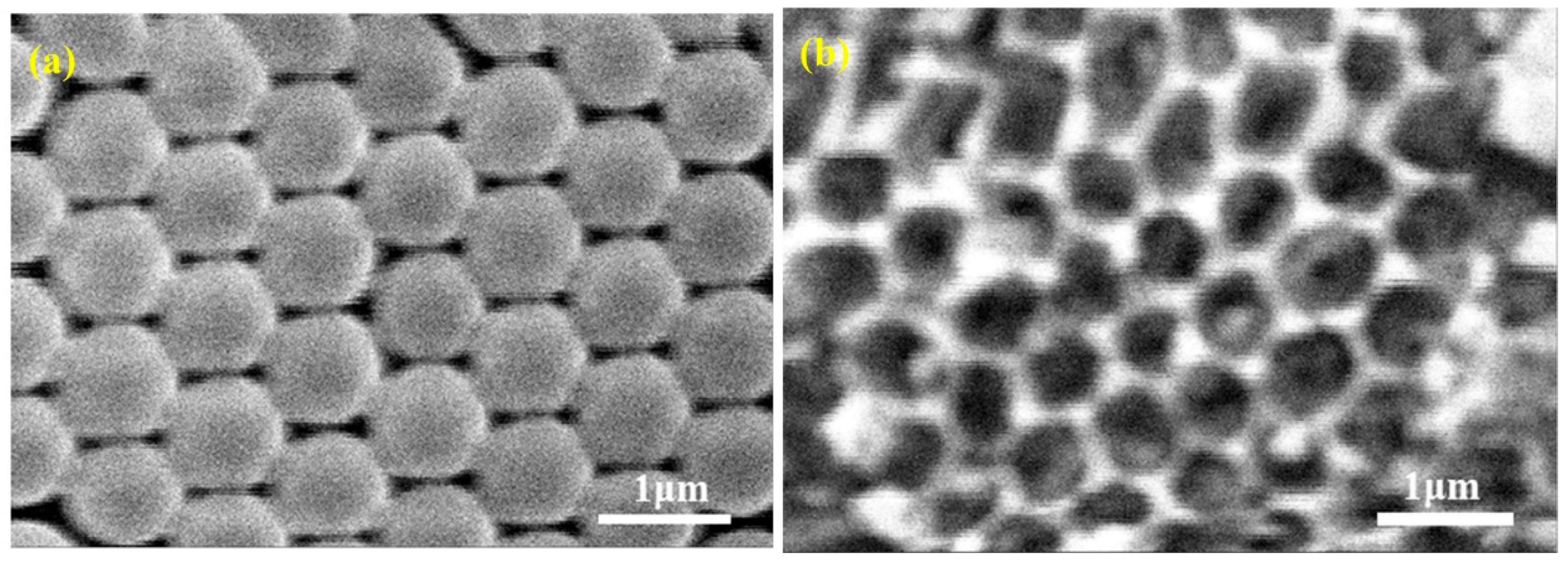
The TiO2 IO was synthesized using a PS microsphere template. Figure 2a,b display the SEM images of the PS microsphere template (800 nm in diameter) and the resulting TiO2 IO film, respectively, revealing a well-ordered arrangement of the PS microspheres. Following sintering, the PS template was removed, leaving behind an ordered TiO2 framework with air holes. Figure 3 presents the SEM images of the surface and cross-section of the TiO2 NRs, showing a uniform distribution of dense TiO2 NRs with a length of approximately 1.5 μm.
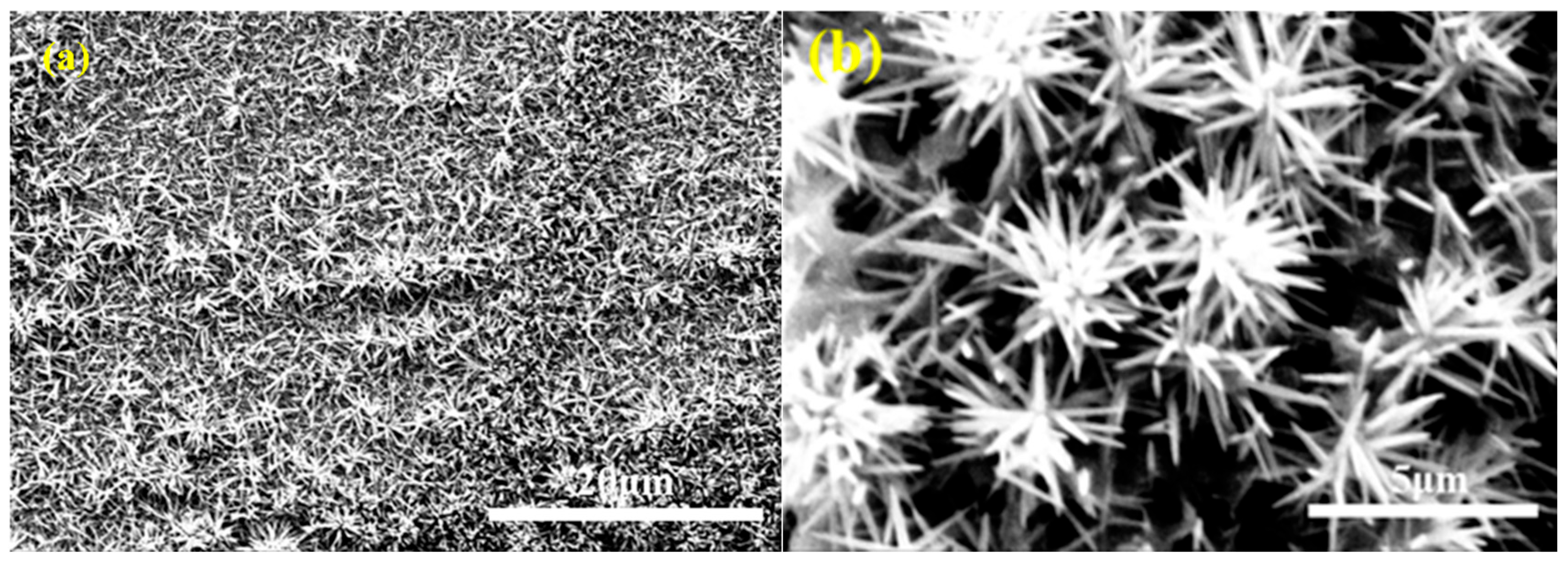
The SEM images of the TiO2 composite, i.e., TiO2 NR/IO, are presented in Figure 4. The morphology of the TiO2 NRs on top of TiO2 IO differs from that of the TiO2 NRs directly prepared on the substrate. As shown in Figure 3, pure TiO2 NRs grow unidirectionally, perpendicular to the FTO glass substrate. In contrast, Figure 4 shows that the TiO2 NRs grow around the three-dimensional TiO2 IO, resembling nanoflowers. The TiO2 composite displays a distinctive hollow three-dimensional morphology, with the NRs uniformly coating the IO surface. This increased surface area would enhance carrier transport and collection within the cells. Figure 4b further illustrates the fine microstructure of the TiO2 composite. As shown, the material exhibits structural features similar to the branched TiO2 nanotube networks reported in the literature. Research has demonstrated that such unique nanostructured oxides can significantly enhance device performance, primarily attributed to their enhanced surface area and the higher dye loading [33].
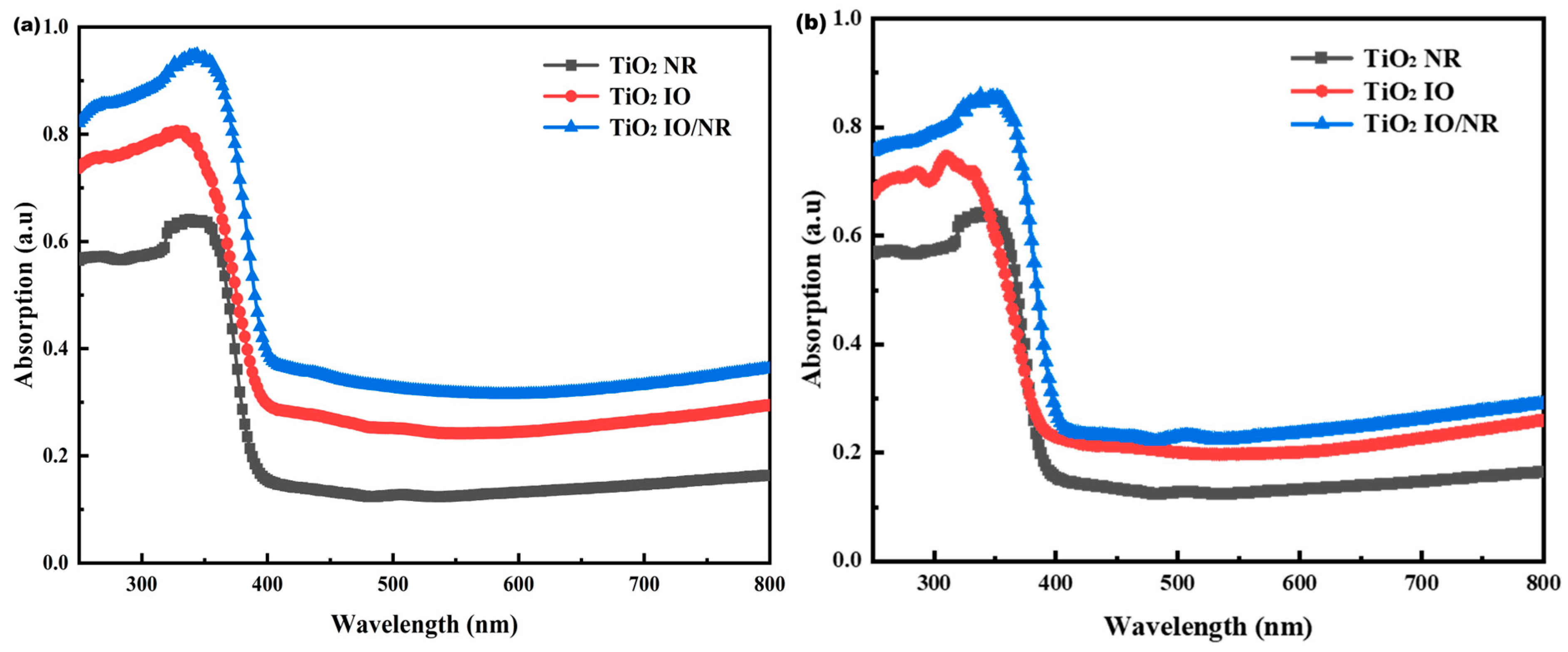
The UV–visible spectra of TiO2 NR, TiO2 IO, and the TiO2 IO/NR composite films are displayed in Figure 5. The TiO2 composite exhibits significantly higher absorption compared to TiO2 IO and TiO2 NRs. The PS templates used for preparing TiO2 IO have varying sphere diameters in Figure 5a,b. Specifically, TiO2 IO and TiO2 IO/NR prepared with 800 nm PS spheres were used in the photoanodes of QDSSCs, with the absorption shown in Figure 5a. It is expected to lead to an increase in light absorption of the photoanode, as evidenced by the enhanced photocurrent [34]. For photocatalytic applications, TiO2 IO and TiO2 IO/NR were prepared using 350 nm PS spheres, and their relative absorption is presented in Figure 5b.
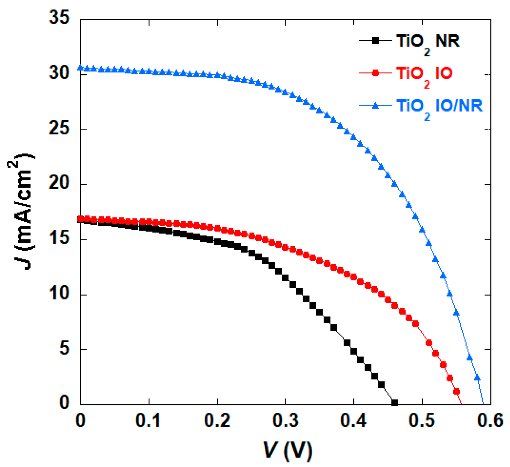
The photovoltaic parameters of the QDSSCs fabricated using TiO2 NR, TiO2 IO, and the composite TiO2 IO/NR in the photoanodes are listed in Table 1, including the short-circuit current density (Jsc), open-circuit voltage (Voc), fill factor (FF), and maximum PCE (η). The J-V characteristics are shown in Figure 6. For the QDSSCs fabricated with pure TiO2 NR or TiO2 IO-based photoanode, moderate cell performances were obtained. The highest PCE of the TiO2 NR-based device was 3.54%, with its Jsc of 16.77 mA/cm2 and Voc of 0.47 V. The TiO2 IO-based QDSSC obtained a higher cell efficiency of 4.64%, with a Jsc of 16.89 mA/cm2 and Voc of 0.56 V. However, the composite TiO2-based photoanode achieved a much higher PCE of 9.73%, more than double that of devices based on pure TiO2 structure. The improved cell efficiency could be due to the enhanced photocurrent. The Jsc of the composite-based solar cell is nearly twice (30.64 mA/cm2) that of single-TiO2 structure-based devices. The Voc of the composite-based cell is also much higher (0.59 V). The observed Voc enhancement under identical electrolyte conditions indicates an upward shift in the electron quasi-Fermi level (EF, n) in the photoanode, as systematically verified by surface photovoltage spectroscopy in previous reports [35]. This EF, n elevation can be mechanistically attributed to promoted electron accumulation in the TiO2 conduction band through facilitated QD-to-TiO2 charge injection.
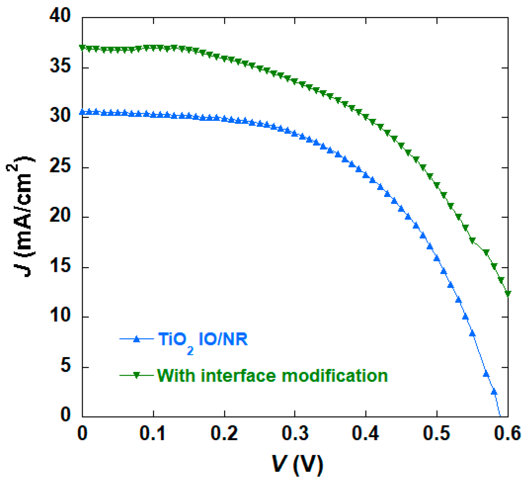
The photovoltaic performance of QDSSCs utilizing the TiO2 composite can be substantially improved by interface modification and surface passivation with NH4F and ZnS, as previously reported [24,36].
This modification leads to improved photocurrent and PCE. With a photoanode structure of TiO2 IO/TiO2 NR/NH4F/CdS/CdSe/ZnS, the QDSSCs attained a remarkable cell efficiency of (12.24 ± 1.3)%, accompanied by Voc of 0.66 V, Jsc of 36.92 mA/cm2, and FF of 0.50. The uncertainty values in parentheses denote the variability in efficiency observed for 6 samples from different batches. The corresponding J-V curve is illustrated in Figure 7. The passivation layer effectively reduces surface dangling bonds and defect states on the quantum dots, thereby suppressing non-radiative recombination. This leads to an increased lifetime and concentration of photogenerated carriers, resulting in an enhancement of the open-circuit voltage [37,38,39].
IPCE was determined by measuring the Jsc at various excitation wavelengths, and the resulting IPCE plots for the QDSSCs are presented in Figure 8. The IPCE spectra align with the observation that the composite TiO2 exhibits greater absorption compared to bare TiO2 IO or TiO2 NRs. Notably, the QDSSC based on TiO2 IO/NR achieved the highest IPCE value across the wavelength range of 400–600 nm, reaching a maximum of 66.6% at 480 nm.
As previously stated, the composite of TiO2 IO and TiO2 NRs features a distinctive hollow, three-dimensional morphology, which facilitates efficient and orderly deposition of QDs, and enhances deeper electrolyte infiltration, improved charge carrier transport, and enhanced collection of charge carriers [34,36,40,41].
The impact of diverse photoanode structures on QDSSC performance was further explored through EIS measurements [42,43]. Figure 9a presents the Nyquist plots for QDSSCs fabricated with photoanodes comprising TiO2 IO, TiO2 NRs, and TiO2 IO/NR composites, obtained across a frequency range of 0.1 to 105 Hz under 100 mW cm−2 illumination at ambient temperature. These plots reveal two semicircles: the larger one at middle frequencies represents the oxide/QD/electrolyte interface impedance, while the smaller one observed at high frequencies signifies the redox impedance at the electrolyte/counter electrode interface. The semicircles can be described by the equivalent circuit model depicted in the inset of Figure 9a, which consists of charge transfer resistances Rct1 at the electrolyte/counter electrode and Rct2 at the oxide/QD/electrolyte interfaces, respectively, a series resistance Rs, and chemical capacitances CPE1 and CPE2. Notably, the TiO2 IO/ TiO2 NR composite exhibits the lowest Rs and Rct values among the TiO2 samples, suggesting superior charge carrier transport at the cell interfaces [34,44,45].
The Bode plots are presented in Figure 9b, and the lifetime (τ) of the electrons is determined by the location of the mid-frequency peak fmax, calculated as
τ = 1/2πfmax,
where fmax denotes the peak frequency within the mid-frequency range [36,44]. The corresponding τ values are provided in Table 2. As illustrated in Figure 9a and Table 2, TiO2 IO exhibits lower Rs, Rct1 and Rct2 values (1.70 Ω, 2.83 Ω, and 7.80 Ω, respectively) compared to TiO2 NR (3.81 Ω, 5.86 Ω, and 12.75 Ω). Moreover, the TiO2 IO/NR composite further reduces these resistances to 1.26 Ω, 0.75 Ω, and 5.03 Ω, respectively. The TiO2 IO-based photoanodes enhance the interface and charge carrier transport compared to TiO2 NR-based ones. Consequently, the TiO2 IO-based devices achieve the longest carrier lifetime of 60.13 ms among the tested devices, while the TiO2 IO/NR composite-based cells have a moderate carrier lifetime of 47.75 ms.
The photocatalytic activity of the TiO2 composite, as well as that of TiO2 IO and TiO2 NRs, was assessed through photocatalytic hydrogen production experiments under visible light irradiation (λ > 320 nm). It was found that TiO2 IO prepared with 380 nm diameter spheres exhibited enhanced photocatalytic efficiency compared to those prepared with larger spheres [22]. Therefore, 350 nm diameter PS spheres were utilized as a template for preparing TiO2 IO for subsequent photocatalytic hydrogen production experiments. Figure 5b displays the UV–visible spectra of TiO2 IO, the TiO2 IO/NR composite, and TiO2 NR, all prepared using 350 nm diameter PS spheres. Similar to the absorption spectra of TiO2 IO and composites prepared using 800 nm diameter PS spheres, the absorption spectrum of TiO2 composites fabricated with 350 nm diameter PS spheres exhibits higher absorption intensity compared to those of standalone TiO2 NR and TiO2 IO.
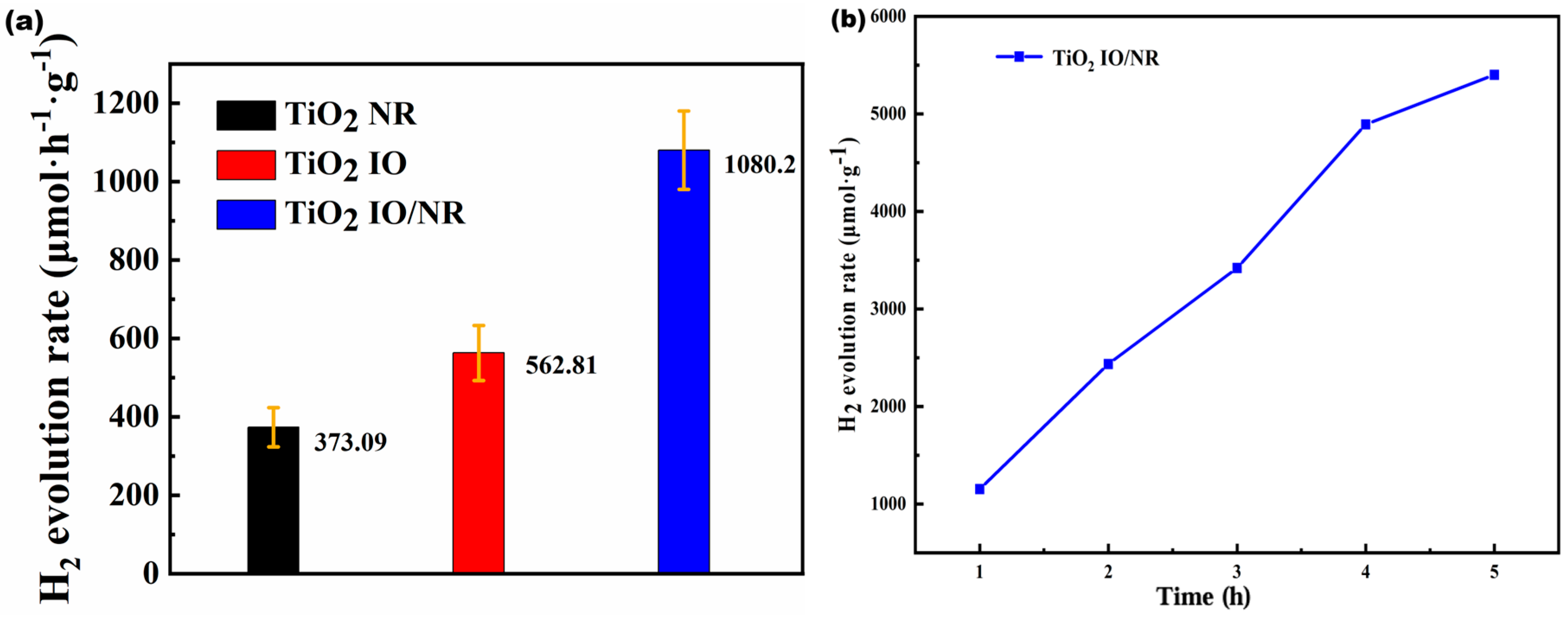
The TiO2 IO/NR composite exhibits superior light absorption capacity and electron-hole separation efficiency, as evidenced by its higher light absorbance and lower PL intensity. Figure 10a illustrates the H2 production rates of TiO2 with various structures. The TiO2 NR film demonstrated a rate of approximately 373.09 μ mol h−1 g−1. The H2 production rate of the TiO2 IO photocatalyst increased to 562.81 μ mol h−1 g−1. Notably, the TiO2 IO/ TiO2 NR composite achieved the highest photocatalytic activity, with an exceptional H2 release rate of 1080.2 μ mol h−1 g−1, nearly twice that of TiO2 IO and almost three times that of TiO2 NR. This significant enhancement is primarily attributed to the increased light absorption area resulting from the larger relative specific surface area, which facilitates the separation of numerous photogenerated electrons and holes on the surface and improves photocatalytic activity. The improved charge separation and carrier lifetimes led to enhanced chemical reduction efficiencies [46]. Figure 10b shows the consistent and gradually increasing slope of hydrogen production over time for the TiO2 IO/NR composite, indicating a stable and steadily rising H2 release rate.
The TiO2 IO/NR composite, featuring a three-dimensional ordered hollow and dendrite-like morphology, boasts an increased surface area, enhanced light absorption, and improved interfacial contact. Studies have demonstrated that TiO2 NR-based DSSCs exhibit lower PCE, primarily attributed to the shorter apparent recombination lifetime of photogenerated electrons in TiO2 NRs compared to sintered TiO2 nanoparticles, ultimately leading to inferior photovoltaic performance—a finding consistent with our experimental results [47]. However, by fabricating TiO2 NRs on TiO2 IO substrates, we not only prevent direct electrolyte contact with the FTO glass (which would cause short-circuiting in conventional NR/FTO configurations), but also synergistically combine the advantages of both nanostructured TiO2 materials, resulting in significant performance enhancement.
This composite exhibits exceptional efficiency in both QDSSCs and photocatalytic hydrogen production. Notably, the film thickness of TiO2 IO and TiO2 NRs can be varied, and studies have been conducted to explore the impact of film thickness on device efficiencies [16,21,22]. By modifying the concentration of reagents or dispersion, as well as the reaction or deposition time, the length of TiO2 NRs and the film thickness of TiO2 IO can be adjusted. However, the influence of film thickness on the photovoltaic and photocatalytic performance of pure TiO2 IO and TiO2 NRs is relatively minor. The optimal film thickness for TiO2 IO and TiO2 NRs was determined based on literature review [16,21], with the high efficiency attributed to the synergistic combination of TiO2 IO and NRs.

4. Conclusions

In this study, a TiO2 composite structure consisting of IO and NR architectures—along with bare TiO2 IO and NR controls—was synthesized and evaluated for photovoltaic and photocatalytic applications. The integration of TiO2 NR onto TiO2 IO substrates significantly enhanced the performance of TiO2-based systems, attributable to improved charge transport and increased specific surface area. Comparative analysis revealed that the TiO2 IO/NR composite exhibited markedly superior light absorption characteristics relative to its individual counterparts. In QDSSCs, devices fabricated with the TiO2 IO/NR composite demonstrated a notable increase in photocurrent density, leading to a power conversion efficiency (PCE) of 12.24%—among the highest reported for systems employing CdS/CdSe sensitizers. This enhancement is attributed to improved light harvesting and reduced charge recombination. Similarly, in photocatalytic hydrogen evolution, the composite material significantly boosted H2 production, achieving a rate of 1080.2 μmol h−1 g−1, which substantially exceeds those of bare TiO2 IO and NR structures. These results underscore the synergistic effect arising from the hierarchical combination of a porous framework with one-dimensional nanostructures. The findings indicate that strategic hybridization of multidimensional nanomaterials can effectively enhance the efficiency of photoelectrochemical and photocatalytic processes. This approach offers a promising pathway for the design of advanced functional materials for solar energy conversion and environmental remediation applications.

Author Contributions

Conceptualization, X.B. and Y.X.; methodology, X.B., J.C. and Y.X.; validation, X.B. and S.D.; formal analysis, X.B. and Y.X.; investigation, X.B. and Y.X.; resources, Y.X.; data curation, X.B. and J.C.; writing—original draft preparation, X.B.; writing—review and editing, Y.X.; supervision, Y.X.; project administration, Y.X.; funding acquisition, Y.X. All authors have read and agreed to the published version of the manuscript.

Funding

This research was supported by the Grants no. T2020008 from the Science Foundation of Educational Commission of Hubei Province of China, no. 2024-skllmd-07 from the Open Fund of the State Key Laboratory of Luminescent Materials and Devices (South China University of Technology).

Data Availability Statement

The raw data supporting the conclusions of this article will be made available by the authors on request.

Conflicts of Interest

The authors declare no conflicts of interest.

Abbreviations

The following abbreviations are used in this manuscript:
DSSCDye-sensitized solar cell
QDSSCQuantum-dot sensitized solar cell
IOInverse opal
NRNanorod
PCEPower conversion efficiency
QDQuantum dot

References

  1. Kokkonen, M.; Talebi, P.; Zhou, J.; Zhou, J.; Asgari, S.; Soomro, S.A.; Elsehrawy, F.; Halme, J.; Ahmad, S.; Hagfeldt, A.; et al. Advanced research trends in dye-sensitized solar cells. J. Mater. Chem. A 2021, 9, 10527–10545. [Google Scholar] [CrossRef]
  2. Chang, Y.C.; Zeng, C.J.; Chen, C.Y.; Tsay, C.Y.; Lee, G.J.; Wu, J.J. NiS/Pt loaded on electrospun TiO2 nanofiber with enhanced visible-light-driven photocatalytic hydrogen production. Mater. Res. Bull. 2023, 157, 112041. [Google Scholar] [CrossRef]
  3. Chang, W.; Wang, H.; Wu, T.; Zhang, S.; Li, Y.; Wang, J.; Yang, Y.; Wang, L. Interfacial lattice matched sub-2 nm RuO2 on rutile TiO2 nanorod for visible light driven CO2 conversion to CH4. J Mater. Sci. Technol. 2025, 235, 28–36. [Google Scholar] [CrossRef]
  4. Sun, K.; Zhang, C.; Yang, C.; Wang, X.; Wan, Z.; Zhao, E.; Xiao, Y.; Zhao, W.; Ma, M.; Chen, D.; et al. A review on conductive polymers-modified TiO2 photocatalyst for environmental remediation. J. Environ. Chem. Eng. 2025, 13, 116518. [Google Scholar] [CrossRef]
  5. Gao, D.; Xu, J.; Yu, H.; Liu, Y.; Yu, J. Hydroxyl-enriched highly crystalline TiO2 suspensible photocatalyst: Facile synthesis and superior H2-generation activity. Chem. Commun. 2021, 57, 2025–2028. [Google Scholar] [CrossRef] [PubMed]
  6. O'regan, B.; Grätzel, M. A low-cost, high-efficiency solar cell based on dye-sensitized colloidal TiO2 films. Nature 1991, 353, 737–740. [Google Scholar] [CrossRef]
  7. Ren, Y.; Zhang, D.; Suo, J.; Cao, Y.; Eickemeyer, F.T.; Vlachopoulos, N.; Zakeeruddin, S.M.; Hagfeldt, A.; Grätzel, M. Hydroxamic acid pre-adsorption raises the efficiency of cosensitized solar cells. Nature 2023, 613, 60–65. [Google Scholar] [CrossRef]
  8. Ji, J.M.; Zhou, H.; Eom, Y.K.; Kim, C.H.; Kim, H.K. 14.2% Efficiency dye-sensitized solar cells by co-sensitizing novel thieno[3,2-b]indole-based organic dyes with a promising porphyrin sensitizer. Adv. Energy Mater. 2020, 10, 2000124. [Google Scholar] [CrossRef]
  9. Chang, Y.; Han, W.; Cui, S.; Cai, A. Cellulose-inspired synthesis of hierarchically nanostructured TiO2 with high photocatalytic activity. Chem. Phys. Lett. 2020, 745, 137249. [Google Scholar] [CrossRef]
  10. Noman, M.T.; Ashraf, M.A.; Ali, A. Synthesis and applications of nano-TiO2: A review. Environ. Sci. Pollut. Res. 2016, 26, 3262–3291. [Google Scholar] [CrossRef]
  11. Sánchez-Godoy, H.E.; López-Luke, T.; Zarazúa, I.; Herrera-Rodríguez, A.; Castañeda-Contreras, J.; Rodríguez-Rojas, R.A. Enhanced photovoltaic efficiency in TiO2-based CdS quantum dot-sensitized solar cells by the introduction of ZnO:Al3+ nanoparticles. Sol. Energy 2024, 281, 112818. [Google Scholar] [CrossRef]
  12. Zeng, H.H.; Rasal, A.S.; Abate, M.A.; Ghule, A.V.; Chang, J. Surface and interfacial engineering for aqueous-processed quantum dots-sensitized solar cell with efficiency approaching 11%. Chem. Eng. J. 2024, 495, 153702. [Google Scholar] [CrossRef]
  13. Sargin, I.; Yanalak, G.; Arslan, G.; Patir, I.H. Green synthesized carbon quantum dots as TiO2 sensitizers for photocatalytic hydrogen evolution. Int. J. Hydrogen Energy 2019, 44, 21781–21789. [Google Scholar] [CrossRef]
  14. Song, H.; Lin, Y.; Zhang, Z.; Rao, H.; Wang, W.; Fang, Y.; Pan, Z.; Zhong, X. Improving the Efficiency of Quantum Dot Sensitized Solar Cells beyond 15% via Secondary Deposition. J. Am. Chem. Soc. 2021, 143, 4790–4800. [Google Scholar] [CrossRef] [PubMed]
  15. Song, H.; Lin, Y.; Zhou, M.; Rao, H.; Pan, Z.; Zhong, X. Zn-Cu-In-S-Se Quinary “Green” Alloyed Quantum-Dot-Sensitized Solar Cells with a Certified Efficiency of 14.4%. Angew. Chem. Int. Ed. 2021, 60, 6137–6144. [Google Scholar] [CrossRef] [PubMed]
  16. Liu, B.; Aydil, E.S. Growth of Oriented Single-Crystalline Rutile TiO2 Nanorods on Transparent Conducting Substrates for Dye-Sensitized Solar Cells. J. Am. Chem. Soc. 2009, 131, 3985–3990. [Google Scholar] [CrossRef]
  17. Pawar, S.A.; Patil, D.S.; Lokhande, A.C.; Gang, M.G.; Shin, J.C.; Patil, P.S.; Kim, J.H. Chemical synthesis of CdS onto TiO2 nanorods for quantum dot sensitized solar cells. Opt. Mater. 2016, 58, 46–50. [Google Scholar] [CrossRef]
  18. Yan, H.; Wang, X.; Yao, M.; Yao, X. Band structure design of semiconductors for enhanced photocatalytic activity: The case of TiO2. Prog. Nat. Sci. 2013, 23, 402–407. [Google Scholar] [CrossRef]
  19. Shi, Y.; Fu, Y.; He, Y.; Zhang, J.; Lin, K.; Song, W.; Yue, X.; Wang, D.; Wu, A.; Tian, C. Ag-Doped hollow Multi-Shelled structure TiO2 for highly selective photocatalytic CO2 reduction. J. Colloid Interface Sci. 2025, 694, 137684. [Google Scholar] [CrossRef]
  20. Wu, M.C.; Lin, T.H.; Hsu, K.H.; Hsu, J.F. Photo-induced disinfection property and photocatalytic activity based on the synergistic catalytic technique of Ag doped TiO2 nanofibers. Appl. Surf. Sci. 2019, 484, 326–334. [Google Scholar] [CrossRef]
  21. Jin, J.; Zhao, L.; Liu, Y.; Gao, S.; Yu, X.; Xiong, Y. Double-layer TiO2 inverse opal-based quantum dot-sensitized solar cells. J. Solid State Electrochem. 2021, 25, 291–299. [Google Scholar] [CrossRef]
  22. Zhang, X.; John, S. Enhanced photocatalysis by light-trapping optimization in inverse opals. J. Mater. Chem. A 2020, 8, 18974–18986. [Google Scholar] [CrossRef]
  23. Senić, Ž.; Bauk, S.; Vitorović-Todorović, M.; Pajić, N.; Samolov, A.; Rajić, D. Application of TiO2 nanoparticles for obtaining self decontaminating smart textiles. Sci. Technol. Rev. 2011, 61, 63–72. [Google Scholar]
  24. Lee, Y.L.; Lo, Y.S. Highly efficient quantum-dot-sensitized solar cell based on co-sensitization of CdS/CdSe. Adv. Funct. Mater. 2009, 19, 604–609. [Google Scholar] [CrossRef]
  25. Pan, Z.; Zhang, H.; Cheng, K.; Hou, Y.; Hua, J.; Zhong, X. Highly efficient inverted type-I CdS/CdSe core/shell structure QD-sensitized solar cells. ACS Nano 2012, 6, 3982–3991. [Google Scholar] [CrossRef] [PubMed]
  26. Sajjad, S.; Sayyad, M.H.; Khan, N.; Manzoor, T.; Nasr, N.; Toor, R.A.; Shah, S.A.A.; Guo, Z. Comparative photovoltaic and impedance spectroscopic study on carbon counter electrode based CdS quantum dot sensitized solar cell using polysulfide and iodide/triiodide as redox liquid electrolytes. Mat. Sci. Eng. B-Adv. 2021, 273, 115437. [Google Scholar] [CrossRef]
  27. Li, D.; Cheng, L.; Zhang, Y.; Zhang, Q.; Huang, X.; Luo, Y.; Meng, Q. Development of Cu2S/carbon composite electrode for CdS/CdSe quantum dot sensitized solar cell modules. Sol. Energy Mater. Sol. Cells 2014, 120 Pt B, 454–461. [Google Scholar] [CrossRef]
  28. Yu, X.; Zhu, J.; Liu, F.; Wei, J.; Hu, L.; Dai, S. Metal chalcogenide complex-mediated fabrication of Cu2S film as counter electrode in quantum dot sensitized solar cells. Sci. China Chem. 2013, 56, 977–981. [Google Scholar] [CrossRef]
  29. Snaith, H.J. The perils of solar cell efficiency measurements. Nat. Photonics 2012, 6, 337–340. [Google Scholar] [CrossRef]
  30. Pazoki, M.; Cappel, U.B.; Johansson, E.M.J.; Hagfeldt, A.; Boschloo, G. Characterization techniques for dye-sensitized solar cells. Energy Environ. Sci. 2017, 10, 672–709. [Google Scholar] [CrossRef]
  31. Green, M.A.; Dunlop, E.D.; Yoshita, M.; Kopidakis, N.; Bothe, K.; Siefer, G.; Hao, X.; Jiang, J.Y. Solar Cell Efficiency Tables (Version 65). Prog. Photovolt. Res. Appl. 2025, 33, 3–15. [Google Scholar] [CrossRef]
  32. Snaith, H.J. How should you measure your excitonic solar cells? Energy Environ. Sci. 2012, 5, 6513. [Google Scholar] [CrossRef]
  33. Qiu, J.; Li, X.; Gao, X.; Gan, X.; Weng, B.; Li, L.; Yuan, Z.; Shi, Z.; Hwang, Y.H. Branched double-shelled TiO2 nanotube networks on transparent conducting oxide substrates for dye sensitized solar cells. J. Mater. Chem. 2012, 22, 23411. [Google Scholar] [CrossRef]
  34. Liu, Y.; Wang, Z.; Li, L.; Gao, S.; Zheng, D.; Yu, X.; Wu, Q.; Yang, Q.; Zhu, D.; Yang, W.; et al. Highly efficient quantum-dot-sensitized solar cells with composite semiconductor of ZnO nanorod and oxide inverse opal in photoanode. Electrochim. Acta 2022, 412, 140145. [Google Scholar] [CrossRef]
  35. Osterloh, F.E.; Daemi, S.; Kundmann, A.; Becker, K.; Cheng, Y. Surface Photovoltage Spectroscopy on BiVO4, Gallium Phosphide, and CuGa3Se5 Photoelectrodes in Contact with Aqueous Electrolytes. In Electrochemical Society Meeting Abstracts; The Electrochemical Society, Inc.: Pennington, NJ, USA, 2022; p. 1575. [Google Scholar]
  36. Diguna, L.J.; Shen, Q.; Kobayashi, J.; Toyoda, T. High efficiency of CdSe quantum-dot-sensitized TiO2 inverse opal solar cells. Appl. Phys. Lett. 2007, 91, 023116. [Google Scholar] [CrossRef]
  37. Alavi, M.; Rahimi, R.; Maleki, Z.; Hosseini-Kharat, M. Improvement of Power Conversion Efficiency of Quantum Dot-Sensitized Solar Cells by Doping of Manganese into a ZnS Passivation Layer and Cosensitization of Zinc-Porphyrin on a Modified Graphene Oxide/Nitrogen-Doped TiO2 Photoanode. ACS Omega 2020, 5, 11024–11034. [Google Scholar] [CrossRef] [PubMed]
  38. Sun, J.; An, L.; Xue, G.; Li, X. Wavefunction engineering for efficient photoinduced-electron transfer in CuInS2 quantum dot-sensitized solar cells. Nanotechnology 2020, 31, 215408. [Google Scholar] [CrossRef] [PubMed]
  39. Wang, Y.; Gu, Z.; Li, L.; Liu, S.; Li, J.; Lu, L.; Li, X.; Liu, W.; Liu, R.; Chen, J.; et al. Interfacial engineering of ZnS passivating contacts for crystalline silicon solar cells achieving 20% efficiency. Mater. Today Energy 2023, 35, 101336. [Google Scholar]
  40. Shin, J.H.; Kang, J.H.; Jin, W.M.; Park, J.H.; Cho, Y.S.; Moon, J.H. Facile synthesis of TiO2 inverse opal electrodes for dye-sensitized solar cells. Langmuir 2011, 27, 856–860. [Google Scholar] [CrossRef]
  41. Seo, Y.G.; Woo, K.; Kim, J.; Lee, H.; Lee, W. Rapid fabrication of an inverse opal TiO2 photoelectrode for DSSC using a binary mixture of TiO2 nanoparticles and polymer microspheres. Adv. Funct. Mater. 2011, 21, 3094–3103. [Google Scholar] [CrossRef]
  42. Fabregat-Santiago, F.; Bisquert, J.; Garcia-Belmonte, G.; Boschloo, G.; Hagfeldt, A. Influence of electrolyte in transport and recombination in dye-sensitized solar cells studied by impedance spectroscopy. Sol. Energy Mater. Sol. Cells 2005, 87, 117–131. [Google Scholar] [CrossRef]
  43. Zarazúa, I.; Esparza, D.; López-Luke, T.; Ceja-Fdez, A.; Reyes-Gomez, J.; Mora-Sero, I.; De la Rosa, E. Effect of the electrophoretic deposition of Au NPs in the performance CdS QDs sensitized solar cells. Electrochim. Acta 2016, 188, 710–717. [Google Scholar] [CrossRef]
  44. Chen, T.P.; Young, S.J.; Chang, S.J.; Hsiao, C.H.; Wu, S.L. Photoelectrical and low-frequency noise characteristics of ZnO nanorod photodetectors prepared on flexible substrate. IEEE Trans. Electron. Dev. 2012, 60, 229–234. [Google Scholar] [CrossRef]
  45. Wang, Q.; Ito, S.; Grätzel, M.; Fabregat-Santiago, F.; Mora-Seró, I.; Bisquert, J.; Bessho, T.; Imai, H. Characteristics of high efficiency dye-sensitized solar cells. J. Phys. Chem. B 2006, 110, 25210–25221. [Google Scholar] [CrossRef]
  46. Reli, M.; Nadrah, P.; Edelmannová, M.F.; Ricka, R.; Škapin, A.S.; Štangar, U.L.; Kočí, K. Photocatalytic CO2 reduction over mesoporous TiO2 photocatalysts. Mater. Sci. Semicond. Process. 2024, 169, 107927. [Google Scholar] [CrossRef]
  47. Wang, M.; Bai, J.; Formal, F.L.; Moon, S.J.; Cevey-Ha, L.; Humphry-Baker, R.; Grätzel, C.; Zakeeruddin, S.M.; Grätzel, M. Solid-State Dye-Sensitized Solar Cells using Ordered TiO2 Nanorods on Transparent Conductive Oxide as Photoanodes. J. Phys. Chem. C 2012, 116, 3266–3273. [Google Scholar] [CrossRef]
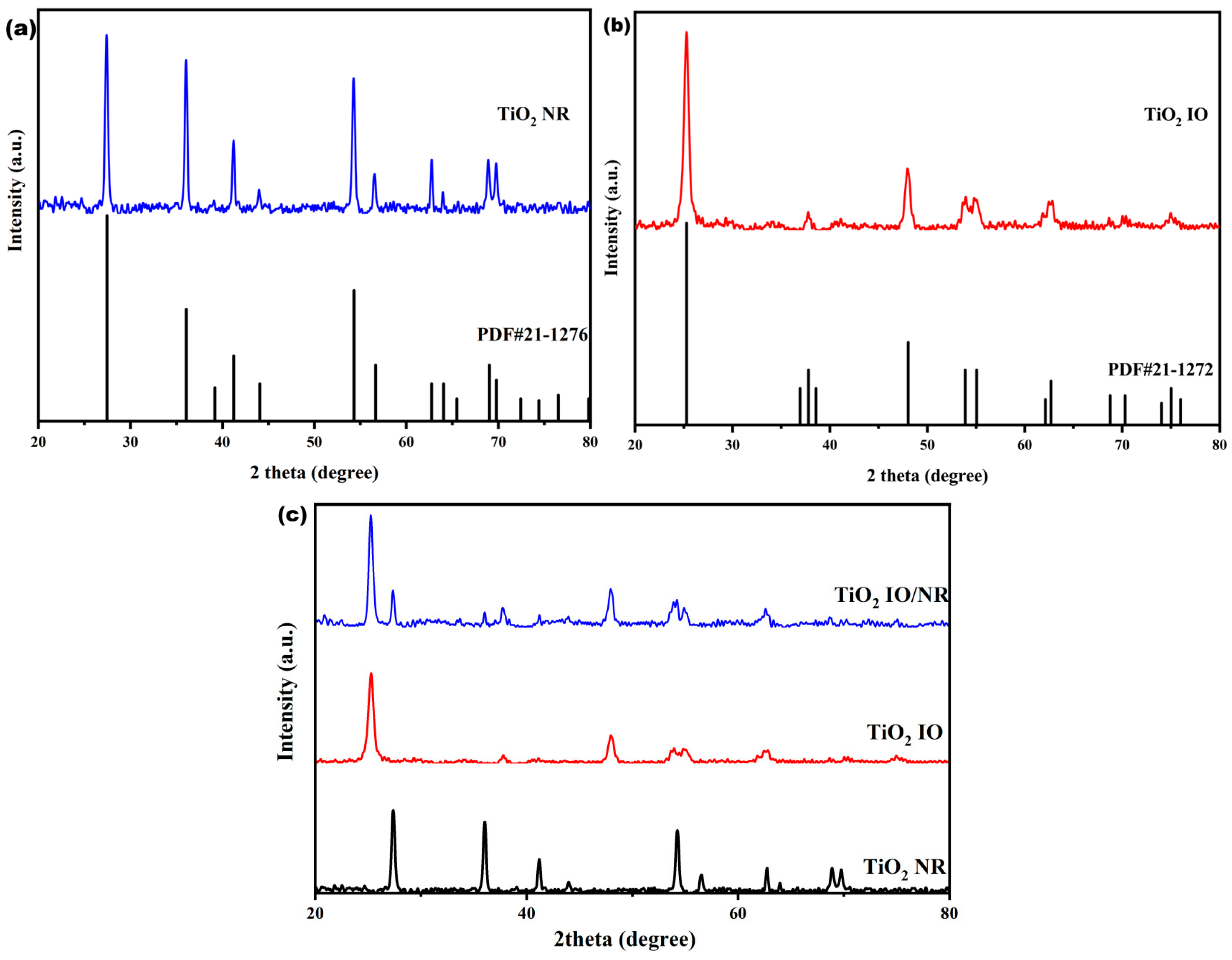
Figure 1. X-ray diffraction pattern of (a) TiO2 NRs, (b) TiO2 IO, and (c) TiO2 IO/NR composite.
Nanoenergyadv 05 00014 g001
Figure 2. SEM images of the surfaces of (a) the PS microsphere template with diameters of 800 nm and (b) the TiO2 inverse opal.
Nanoenergyadv 05 00014 g002
Figure 3. SEM images of (a) the surface and (b) the cross-section of the TiO2 nanorods.
Nanoenergyadv 05 00014 g003
Figure 4. SEM images of TiO2 composite surface prepared with PS sphere of diameter of 800 nm: (a) low-magnification and (b) high-magnification views.
Nanoenergyadv 05 00014 g004
Figure 5. Visible absorption spectra of TiO2 NR, TiO2 IO, and the TiO2 IO/NR films, with TiO2 IO prepared with PS templates of sphere diameters of (a) 800 nm and (b) 350 nm.
Nanoenergyadv 05 00014 g005
Figure 6. Current density-potential (J-V) characteristics of the QDSSCs.
Nanoenergyadv 05 00014 g006
Figure 7. Current density-potential (J-V) characteristics of the QDSSCs based on TiO2 IO/NR with and without interface modification of NH4F and ZnS.
Nanoenergyadv 05 00014 g007
Figure 8. Incident photon-to-charge current conversion efficiency (IPCE) of QDSSCs.
Nanoenergyadv 05 00014 g008
Figure 9. (a) Nyquist plot and (b) Bode plot of QDSSCs (under 100 mW cm−2 illumination and with frequency ranging from 0.1 Hz to105 Hz at room temperature). Inset: Equivalent circuit model of the QDSSCs.
Nanoenergyadv 05 00014 g009
Figure 10. (a) Photocatalytic efficiencies of TiO2 NR, TiO2 IO, and TiO2 IO/NR composite for H2 generation. (b) Photocatalytic H2 generation from TiO2 IO/NR composite versus illumination time.
Nanoenergyadv 05 00014 g010
Table 1. Photovoltaic parameters of the QDSSCs with TiO2 NR, TiO2 IO, and TiO2 IO/NR composite in the photoanode.
TiO2 MorphologyVoc (V)Jsc (mA/cm2)η (%)FF
NR0.4716.773.54 (±0.5) *0.45
IO0.5616.894.64 (±0.7)0.49
IO/NR0.5930.649.73 (±1.0)0.54
* The values in parentheses denote the variability in efficiency observed for multiple samples from different batches.
Table 2. Parameters obtained by fitting the impedance spectra of QDSSC according to the equivalent circuit model shown in the illustration in Figure 9a.
TiO2 MorphologyRs (Ω)Rct1 (Ω) Rct2 (Ω) τ (ms)
NR3.815.8612.7523.69
IO1.702.837.8060.13
IO/NR1.260.755.0347.75
Disclaimer/Publisher’s Note: The statements, opinions and data contained in all publications are solely those of the individual author(s) and contributor(s) and not of MDPI and/or the editor(s). MDPI and/or the editor(s) disclaim responsibility for any injury to people or property resulting from any ideas, methods, instructions or products referred to in the content.